
Full-height shear wall segment design is defined as the structural method of dividing a wood-framed wall into discrete, full-height panels between openings, where each panel resists lateral forces independently with dedicated anchorage. This approach is governed by standards including IRC Section R602.10 and American Wood Council (AWC) protocols, making it the foundation of lateral resistance in wood buildings. Engineers and architects who understand the segmented method gain predictable load paths, clear hold-down requirements, and code-compliant documentation. This guide covers the key differences between segmented and perforated walls, prescriptive versus engineered criteria, step-by-step segment length calculations, and documentation best practices for wood-framed construction.
What is full-height shear wall segment design?
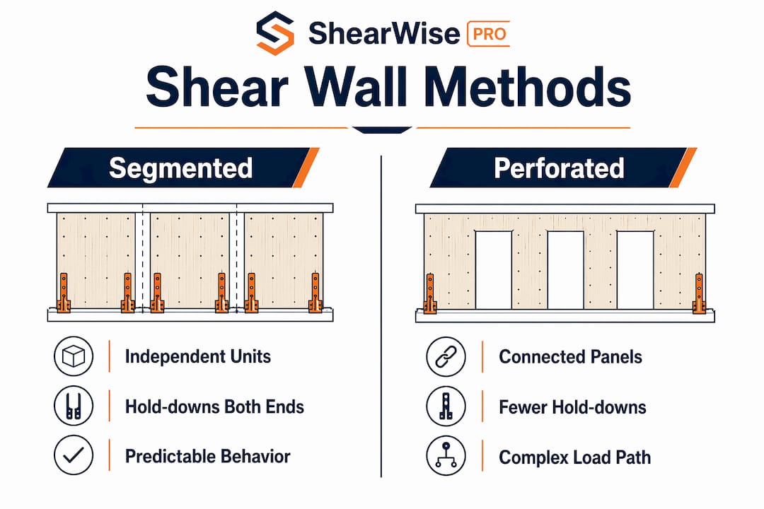
Full-height shear wall segment design treats each wall panel as an independent structural unit. The segmented method distributes shear load to each panel proportional to its stiffness, with hold-downs anchored at both ends of every segment. This method delivers higher unit shear resistance than the perforated approach. The tradeoff is physical restriction: every opening boundary requires a hold-down, which affects framing layout and architectural planning.
The segmented method is the preferred choice when lateral demands are high or when the wall line contains large openings that would otherwise disqualify a perforated analysis. Engineered segmented shear walls allow shorter segment lengths and higher unit shear capacities compared to prescriptive braced wall panels. That flexibility makes engineered design the standard practice in Seismic Design Categories C through F and in high wind zones.

How do segmented shear walls differ from perforated shear walls?
The choice between segmented and perforated design is a pivotal early decision that affects both structural predictability and architectural flexibility. Understanding the distinction prevents costly redesign later.
Segmented method:
- Each full-height panel is treated as an independent shear wall element.
- Hold-downs are required at both ends of every segment.
- Shear load distributes to each segment in proportion to its stiffness.
- No credit is taken for sheathing above or below openings.
- Unit shear capacity is higher and directly calculable per panel.
Perforated method:
- The entire wall line is treated as a single element with a shear capacity reduction factor.
- Opening size and total opening area relative to wall area drive the reduction.
- Fewer hold-downs are required, only at the wall line ends.
- Unit shear capacity is lower because the reduction factor penalizes large or numerous openings.
- Architectural flexibility is greater, but structural efficiency is reduced.
Pro Tip: Decide between segmented and perforated methods during schematic design, not during construction documents. Changing methods late forces recalculation of all hold-down locations, anchorage schedules, and sheathing specifications.
The segmented method gives you a cleaner load path and more predictable behavior under seismic or wind loading. The perforated method works well for walls with many small, evenly distributed openings where hold-down hardware conflicts are a concern.
Prescriptive vs. engineered shear wall panels: what the code requires
IRC Section R602.10 defines prescriptive braced wall panels with fixed dimensional criteria. Prescriptive panels require minimum widths of 4 feet under standard conditions, though continuous sheathing methods allow narrower panels. The percentage of the wall line that must be braced depends on seismic and wind exposure. In high seismic or wind zones, up to 50% of the wall line must be braced. In low-demand areas, 25% may satisfy the requirement.
Prescriptive methods apply fixed panel dimensions regardless of actual load demand. That rigidity limits architectural freedom, particularly in open-plan floor layouts or facades with large glazing. Engineered design removes that constraint by sizing each segment to the actual lateral load it carries.
| Criterion | Prescriptive (IRC R602.10) | Engineered design |
|---|---|---|
| Minimum panel width | 4 ft (standard), less with CS method | Based on aspect ratio and load |
| Bracing percentage | 25%–50% of wall line | Determined by analysis |
| Hold-down requirement | Per table, not always required | Required at each segment end |
| Seismic/wind flexibility | Limited by fixed tables | Fully load-responsive |
| Documentation required | Code table reference | Engineered calculations and schedules |
Pro Tip: In Seismic Design Category D or higher, prescriptive bracing rarely satisfies the aggregate length requirement for open-plan layouts. Switch to engineered design early to avoid adding walls that conflict with the architectural program.
Continuous sheathing methods allow narrower segments alongside openings by crediting sheathing above and below the opening, but they require engineering oversight for code compliance. The stiffness adjustments and aspect ratio checks add calculation time, so weigh that cost against the architectural benefit before specifying this approach.
How to calculate full-height shear wall segment length and stiffness
Segment length calculation follows a defined sequence. Skipping any step produces errors in hold-down sizing and load distribution.
-
Measure the clear width of each segment. The clear width is the horizontal distance between the edges of adjacent openings, or between an opening and the wall end. Do not include the width of any opening, header, or trimmer zone.
-
Check the aspect ratio. Most code tables limit the height-to-width ratio of a shear wall segment to 3.5:1 for standard sheathing. A wall that is 9 feet tall requires a minimum segment width of approximately 2.57 feet under that limit. Segments that fail the aspect ratio check cannot be counted in the lateral analysis.
-
Assign stiffness to each segment. Stiffness is proportional to segment width when sheathing type and fastener schedule are uniform across the wall line. A 4-foot segment carries twice the shear load of a 2-foot segment on the same wall line. For walls with mixed sheathing types, calculate stiffness individually for each segment.
-
Distribute the total lateral load. Divide the total shear force at the wall line among segments in proportion to their stiffness values. This gives the design shear force per segment in pounds per linear foot (plf).
-
Size the sheathing and fastener schedule. Match the calculated unit shear (plf) to the appropriate row in the AWC Special Design Provisions for Wind and Seismic (SDPWS) shear wall capacity tables. Select sheathing thickness, panel grade, and nail size and spacing accordingly.
-
Calculate hold-down forces. Hold-downs must be placed at each segment end to resist overturning. The hold-down tension force equals the overturning moment divided by the segment width, minus the dead load stabilizing moment. Use the net uplift value to select a hold-down device from manufacturer load tables.
| Segment width | Aspect ratio (9-ft wall) | Relative stiffness | Typical hold-down demand |
|---|---|---|---|
| 2 ft | 4.5:1 (fails standard limit) | N/A | N/A |
| 3 ft | 3.0:1 (passes) | 1.0 | High |
| 4 ft | 2.25:1 (passes) | 1.33 | Moderate |
| 6 ft | 1.5:1 (passes) | 2.0 | Lower |
Pro Tip: Always recalculate hold-down forces after any architectural change that shifts an opening location. A 1-foot shift in a window can change the segment width, stiffness ratio, and hold-down demand across the entire wall line.
Design detailing and documentation for shear wall segments
Clear documentation is what separates a buildable set of construction documents from one that generates RFIs and field errors. Shear wall schedules are the core deliverable.
A complete shear wall schedule includes:
- Segment ID and location reference (wall line and grid coordinates)
- Clear segment length and wall height
- Sheathing type, thickness, and panel grade
- Nail size and spacing at panel edges and field
- Unit shear capacity in plf, referenced to the SDPWS table used
- Hold-down device designation and anchor bolt size at each segment end
- Sill plate anchor bolt spacing along the segment base
Detailed schedules and notes improve constructability and inspection outcomes. Inspectors can verify sheathing nailing, hold-down installation, and anchor bolt placement directly against the schedule without interpreting general notes.
"Documentation of shear wall segments should include shear wall schedules with panel lengths, unit shear capacities, anchorage details, and references to code sections for clarity and permit compliance."
Architectural coordination is the other half of good documentation. Opening placement drives segment geometry. When architects locate windows and doors without input from the structural engineer, the resulting segments often fail aspect ratio checks or produce hold-down conflicts with plumbing and mechanical runs. Schedule a joint review of the floor plan before the structural layout is finalized.
Common documentation pitfalls include omitting hold-down locations from the architectural floor plan, failing to note sheathing panel orientation (vertical vs. horizontal blocking requirements), and leaving transfer strap details off the framing plan. Each omission generates a field question that delays the inspection.
Digital tools reduce these errors significantly. Shearwisepro organizes wall lines, openings, full-height segments, hold-down forces, transfer straps, and anchorage data in one place and generates clean PDF reports for permit submittal and review coordination.
Key takeaways
Full-height shear wall segment design requires correct aspect ratios, stiffness-based load distribution, and hold-down anchorage at every segment end to produce a code-compliant lateral system.
| Point | Details |
|---|---|
| Segmented vs. perforated | Choose the method during schematic design; changing it late forces full recalculation of hold-downs and sheathing. |
| Prescriptive limits | IRC R602.10 requires 25%–50% of the wall line to be braced depending on seismic and wind zone. |
| Aspect ratio check | Segment width must satisfy the height-to-width ratio limit before it can carry shear load in the analysis. |
| Hold-down at every end | Each full-height segment requires a hold-down device at both ends sized to the net overturning uplift. |
| Documentation quality | A complete shear wall schedule with unit shear values, anchorage details, and code references prevents field errors. |
Why architects and engineers need to talk before the wall layout is set
The most expensive shear wall problems I have seen share one cause: the structural engineer received a floor plan with all the openings already fixed. By that point, the architect has coordinated window sizes with the facade, the mechanical engineer has routed ducts through the wall cavities, and the owner has approved the layout. Asking for a 2-foot shift in a window to create a viable shear segment feels like a major disruption. It is not. But it feels that way because the conversation happened too late.
Failure to coordinate hold-down locations early frequently causes late-stage construction document revisions and costly rework. I have watched projects add steel moment frames at the permit stage because no viable shear wall segments existed in the wall lines the architect had designed. That is a budget and schedule problem that a 30-minute early coordination meeting would have prevented.
The other thing I have learned is that engineers often accept bad segment geometry because they are trying to avoid conflict with the architect. A 2-foot segment that fails the aspect ratio check is not a shear wall. Calling it one on the drawings does not make it one. The building department will catch it, or worse, the building will not perform as designed.
Use software that shows you segment geometry and hold-down locations in real time as you adjust the wall layout. That visual feedback changes the conversation with architects from adversarial to collaborative. When both parties can see the structural consequence of moving an opening, the decision becomes straightforward.
— Evalin
Shearwisepro: shear wall segment calculations and reports in one place
Shearwisepro handles the full workflow for full-height shear wall segment design in 1-story and 2-story wood buildings.
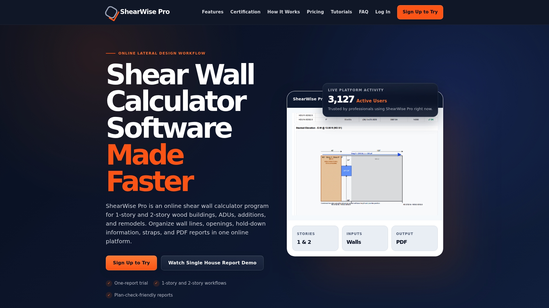
Shearwisepro automates segment length calculations, stiffness distribution, hold-down force outputs, and code compliance checks. It organizes wall lines, openings, transfer straps, and anchorage data in a single project file. The platform generates clean PDF reports formatted for permit submittal and architect-engineer coordination. Engineers and architects can review training videos to get up to speed quickly, or pursue Shearwisepro certification to demonstrate proficiency in the full shear wall report workflow.
FAQ
What is a full-height shear wall segment?
A full-height shear wall segment is a continuous, sheathed wall panel between openings that spans the full story height and resists lateral loads independently. Each segment requires hold-down anchorage at both ends to resist overturning forces.
How is shear wall segment length calculated?
Segment length is the clear horizontal distance between adjacent openings or wall ends. Each segment must pass an aspect ratio check (typically 3.5:1 height-to-width maximum) before it can be included in the lateral force distribution.
When is engineered shear wall design required instead of prescriptive?
Engineered design is required when prescriptive IRC R602.10 tables cannot provide sufficient aggregate braced wall length, which commonly occurs in high seismic zones, open-plan layouts, or walls with large glazing areas.
What is the difference between segmented and perforated shear wall methods?
The segmented method treats each full-height panel as an independent element with hold-downs at both ends. The perforated method treats the entire wall as one element with a capacity reduction factor, requiring fewer hold-downs but delivering lower unit shear resistance.
What must a shear wall schedule include?
A complete shear wall schedule lists segment length, wall height, sheathing type and thickness, nail size and spacing, unit shear capacity in plf, hold-down device designation, and anchor bolt size and spacing at the segment base.