

Run your shear wall design through one sequence: project setup → wall lines and openings → loads → connectors → capacity checks → PDF export. That order holds whether you're working a two-story wood-framed house or a twelve-story concrete core, though the tools you use to execute it diverge fast.
- Set up project metadata, code edition, and material properties
- Draw wall lines, place openings, and split full-height segments
- Apply lateral loads and tributary areas
- Assign hold-downs, straps, and chord elements
- Run capacity checks for shear, overturning, and drift
- Export a reviewed PDF or DWG/IFC report package
For 1 or 2 story wood buildings, a focused calculator gets you through all six steps in under an hour. For reinforced concrete or anything past two stories, you need a BIM-integrated workflow that pulls forces directly from an analysis model. Both paths matter, and picking wrong wastes a full day of rework.
Key Takeaways
A reliable shear wall software workflow moves through project setup, geometry, loads, connectors, and capacity checks before any report gets exported for review.
| Point | Details |
|---|---|
| Match tool to project | Use a focused calculator for 1 to 2 story wood buildings and a BIM-integrated suite for concrete or multi-story work. |
| Sequence stays fixed | Project setup, wall lines and openings, loads, connectors, capacity checks, then export applies to both workflows. |
| Placement drives outcomes | Even wall distribution and continuous wall lines from roof to foundation prevent late-stage drift failures. |
| Version control prevents errors | Archive prior reports and rerun checks after every geometry or connector change to keep submissions current. |
| ShearWise Pro covers the wood path | It runs wall lines, connectors, and checks into a clean PDF report for 1 to 2 story projects without BIM overhead. |
Table of Contents
- The Shear Wall Software Workflow for Wood-Framed Buildings
- Running a BIM-Integrated Workflow for Concrete Shear Walls
- How to Choose the Right Shear Wall Design Workflow
- Verification Checks Before You Export Your Report
- How ShearWise Pro Runs This Workflow for Wood Projects
- Placing Shear Walls for Better Performance Before You Finalize the Model
- Getting Analysis Results Ready for Code Compliance Review
- Managing Model Versions as Your Design Changes
- Rolling Out a New Shear Wall Workflow on Your Team
- Start Running This Workflow With ShearWise Pro
- Sources
The Shear Wall Software Workflow for Wood-Framed Buildings
Wood shear wall design lives and dies on how cleanly you handle geometry and connector assignments. Here's the sequence a focused calculator expects you to follow.
Start with project setup. Enter the project address, select your applicable code edition, and confirm wall sheathing and framing species. Story heights get locked in here too, since they drive your aspect ratio checks downstream.
Draw and define your wall lines next. Place each shear wall line on the plan, then mark door and window openings so the software can split full-height segments automatically. This is where most rework happens: an opening placed six inches off from the architectural plan throws off every segment length behind it, so cross-check against the latest floor plan before moving on.
Assign lateral loads. Residential calculators typically allow input of lateral loads either directly or by simplified tributary areas. Confirm the diaphragm is flagged flexible or rigid correctly. That single toggle changes how load distributes across every wall line on the story.
Assign connectors. This means hold-downs at wall ends, straps across openings, and chord elements where segments need continuity. A good workflow generates a connector summary table automatically, listing manufacturer part numbers and required capacities side by side.
Run your capacity checks. The software evaluates shear capacity, overturning, and story drift against your code limits. When a wall fails, adjust sheathing nailing, add a segment, or swap a hold-down before rerunning, rather than fighting the numbers by hand.
Generate the report. A clean PDF should include a cover sheet, wall line diagrams, connector schedules, hold-down forces, and story drift results, in that order, ready for the plan reviewer to stamp.
- Ensure your code edition aligns with jurisdictional requirements, not necessarily the newest publication
- Check that every opening on the plan matches your architectural set exactly
- Verify hold-down capacities against actual manufacturer catalog values, not generic placeholders
Pro Tip: Save your wall line and connector templates by project type. A repeatable two-story spec home takes a fraction of the setup time once your defaults are dialed in.
Running a BIM-Integrated Workflow for Concrete Shear Walls

Concrete and multi-story shear walls need a different playbook. You're not drawing lines directly in a calculator. You're moving geometry and forces out of an authoring model, and into a design module built for reinforcement.
Start by preparing shear wall families and analytical cross sections inside your Revit or IFC model. Tutorials on this kind of seismic BIM workflow stress checking which walls actually participate in the horizontal bracing system and assigning cross sections to them before running anything, according to SOFiSTiK's seismic BIM tutorial.
From there, export the geometry and internal forces into your shear wall design module rather than re-entering them by hand. Importing geometry and forces directly from a structural analysis model into a design tool cuts out manual data transfer and feeds straight into automated reinforcement design and fabrication outputs, per Autodesk University's fabrication workflow session.
Once forces are loaded, choose your design method. Simplified methods work for straightforward rectangular walls; general methods handle irregular geometry and coupling beams. Run reinforcement and coupling-beam checks, then move to output.
- Produce reinforcement drawings and bar schedules directly from the design module
- Export to DWG, DXF, or IFC so detailers and fabricators work from the same model
- Confirm coupling beam reinforcement is flagged separately from wall pier steel
Model-linked calculation reports update automatically when you revise the model, which matters most on projects with several design iterations, a claim borne out by Tekla Structural Designer's product documentation. BIM overhead pays off once a project involves multiple stories, fabrication drawings, or coordination across three or more disciplines. Below that threshold, you're carrying modeling burden you don't need.
How to Choose the Right Shear Wall Design Workflow
Match the tool to the project, not the other way around. Industry guidance on this is consistent: focused calculators suit low-rise wood residential buildings, while BIM-integrated suites are preferred for taller, concrete, or fabrication-demanding projects, according to Tekla's guidance on matching software capability to project scale.
Ask yourself four questions before committing:
- How many stories, and what material? Two-story wood favors a calculator; anything taller or concrete favors BIM.
- What documentation does the reviewer expect? A permit set needs a clean PDF; a fabrication contract needs DWG or IFC exports.
- How mature is your team's BIM workflow? A calculator skips the modeling learning curve entirely.
- Do you need reinforcement schedules and detailing outputs, or just calculation verification?
Speed and clarity favor the focused calculator every time on small residential work. Integration and automation favor BIM once fabrication or multi-discipline coordination enters the picture, a checklist worth reviewing alongside general engineering workflow integration guidance before you commit a team to either path.
For onboarding, build wall section templates, connector schedules, and load presets ahead of your first live project, standardize your input naming conventions across the team, and assign one reviewer per project to run the QA checklist before any report goes out the door.
Verification Checks Before You Export Your Report
Run these checks before generating any final report. Skipping them is the single biggest cause of plan review rejections.
- Confirm load-path continuity from roof to foundation, with no wall line left unassigned
- Verify wall aspect ratios fall within your code's allowable limits, and confirm sheathing and fastener schedules match what's specified on the architectural plan
- Validate hold-down and strap totals against manufacturer capacity tables, and double-check anchorage embedment depths
- Run story drift checks and compare results directly against your code's drift limit for the applicable risk category
- Cross-check your plan view against elevation views. Connector schedules should list identical quantities in both
Pro Tip: Print your wall line diagram and connector schedule side by side before submitting. A visual mismatch jumps out in seconds; it can hide for an hour inside a spreadsheet.
How ShearWise Pro Runs This Workflow for Wood Projects
ShearWise Pro covers the full wood workflow end to end: wall lines, openings, connectors, capacity checks, and a clean PDF report, without the modeling overhead a BIM suite demands.
- Wall line and opening setup in a browser, no CAD import required
- Automatic hold-down, strap, and chord summaries generated with your report
- Drift and overturning checks built into the same pass as shear capacity
- Tutorials walk through a full two-story project start to finish
Placing Shear Walls for Better Performance Before You Finalize the Model
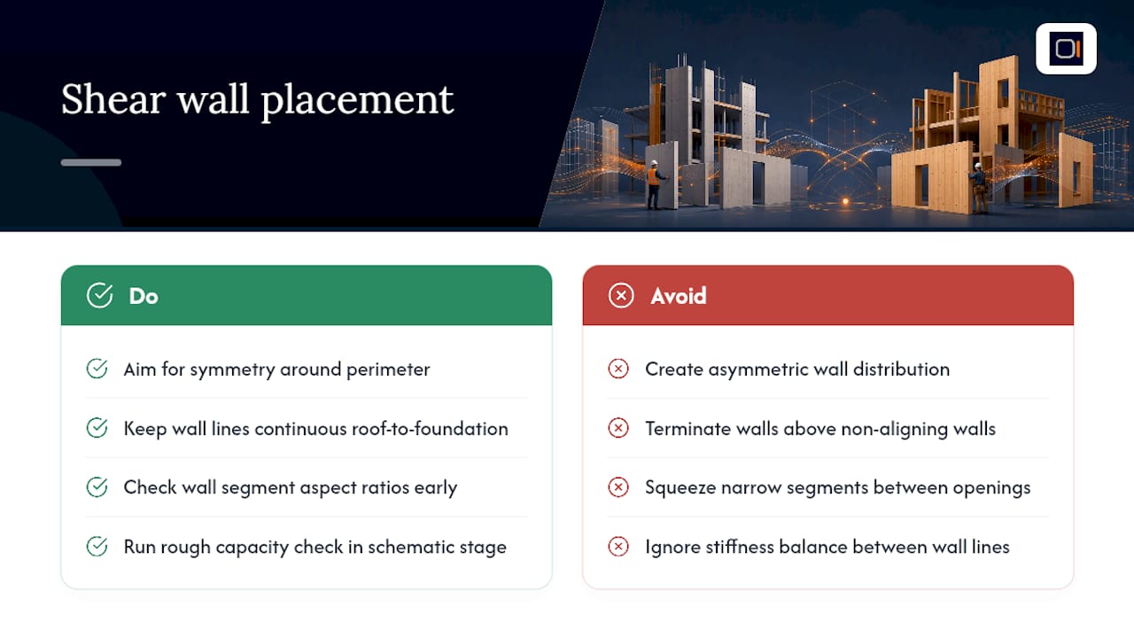
Placement decisions made before you run a single check save more rework than any setting inside the software. Aim for symmetry first. Walls distributed evenly around the building's perimeter minimize torsional irregularity, which shows up as excessive rotation under lateral load and fails drift checks even when individual wall capacities look fine.
Keep wall lines continuous from roof to foundation wherever the floor plan allows. A shear wall that stops at the second floor and doesn't align with a wall below forces a transfer condition, adding cost and complexity that a shifted door or window opening could have avoided.
Watch your aspect ratios early, not after the first failed check. A narrow wall segment squeezed between two openings often can't carry the load a code allows without stepping up sheathing thickness or nailing schedule, so testing segment width against your rough load estimate before you finalize architectural openings prevents a late redesign.
Balance stiffness between wall lines on each axis. Two exterior walls of dramatically different length or hold-down capacity on the same line pull load unevenly, and a small imbalance in early design becomes a rejected drift check three revisions later. Run a rough capacity estimate for each wall line during schematic design, before openings and finishes lock the plan down. A five-minute check at that stage catches placement problems a formal model would only reveal after hours of input work.
Getting Analysis Results Ready for Code Compliance Review
Your report needs to answer the reviewer's questions on the first read. That means every exported page should tie directly back to the code section it satisfies, not just a raw number.
Structure your export so shear capacity, overturning ratios, and drift results each reference the applicable code equation or table number. A plan reviewer checking your submission against IBC or ASCE 7 provisions moves faster when your report cites the same section numbers they're checking against, and faster reviews mean fewer resubmission cycles.
For BIM-driven concrete projects, export reinforcement drawings and schedules to formats your detailing team can use directly. BIM-integrated shear wall tools commonly support DWG, DXF, and IFC exports specifically to move reinforcement data into fabrication workflows without re-drawing it, according to CYPE's documentation for StruBIM Shear Walls. That single export step replaces what used to be a manual redraw between design and detailing teams.
Before you submit anything, run one more pass matching your exported connector schedule against your drift results page. Reviewers cross-reference these two sections first, and a mismatch between them is the fastest way to trigger a request for clarification. Build this cross-check into your standard export routine rather than treating it as optional.
Managing Model Versions as Your Design Changes
Shear wall models change constantly during design development. Architectural revisions move a door, a structural engineer adjusts a footing, and your wall line layout has to follow. Building a version control habit into your workflow prevents the classic failure mode: submitting a report generated from an outdated wall configuration.
Name every saved version with the date and a short revision note, not just "v2" or "final." When three team members touch the same project, a vague filename guarantees confusion about which version fed the last exported report.
For BIM-integrated projects, the advantage of a model-linked workflow shows up here directly. Reports linked to the BIM model update automatically whenever wall geometry or loads change, cutting the rework that comes from manually re-entering every change into a separate calculation file, a benefit documented in Tekla Structural Designer's product overview.
For focused wood calculators without that live model link, build a simple habit instead: rerun your full capacity and drift check any time a wall line, opening, or connector changes, even a minor one. Keep your prior PDF report archived alongside the new one so a reviewer or teammate can see exactly what changed between revisions. That single habit, more than any software feature, is what keeps a fast-moving residential project from submitting a report that no longer matches the current plan.
Rolling Out a New Shear Wall Workflow on Your Team
Roll out any new workflow in stages: pilot it on one live project, lock down templates once it works, train the rest of the team, then run a QA loop for the first several submissions.
Speed matters, but traceability matters more. A fast report that can't be cross-checked against your plan set six months later during a field question isn't actually saving you time.
We've synthesized this workflow from how focused calculators and BIM-integrated suites actually structure their steps, not from a single firm's internal process.
— Evalin
Start Running This Workflow With ShearWise Pro
Everything in this workflow, from wall line setup through connector summaries to a reviewed PDF, is what ShearWise Pro was built to handle for 1 and 2 story wood-framed projects. Instead of carrying BIM modeling overhead onto a job that doesn't need it, you draw wall lines, assign hold-downs and straps, run your capacity and drift checks, and export a permit-ready report in the same session.

New users get three watermarked reports free, enough to run a real project end to end before deciding if it fits your workflow. Walk through a sample tutorial to see a full two-story project processed start to finish, or head straight to the ShearWise Pro product page to start your trial and generate your first report today.
Sources
- Structural design and fabrication workflow: 3D reinforcement (Autodesk University)
- StruBIM Shear Walls workflow and export capabilities (CYPE)