
Diaphragm chords are defined as the tension and compression edge members of a horizontal diaphragm that resist axial forces generated by lateral loading. The role of diaphragm chords in lateral design is to act as the flanges of a deep beam, collecting and transferring shear forces from the diaphragm deck to vertical lateral force-resisting elements such as shear walls and braced frames. Without properly designed chords, the diaphragm cannot complete its load path, regardless of deck strength or fastener quality. ASCE 7 Section 12.10 and guidance from the Steel Joist Institute both treat chord design as a system-level requirement, not an afterthought. The diaphragm system includes the deck, chords, collectors, fasteners, and vertical resisting elements working together.
How do diaphragm chords function within lateral force-resisting systems?
Diaphragm chords act like flanges of a deep beam, resisting the global bending moment that develops when lateral forces load the diaphragm. The deck web carries shear, while the chords carry the resulting tension and compression at opposite edges. That division of labor is what makes the diaphragm work as a structural unit.
During a seismic or wind event, the chord on the tension side elongates while the chord on the compression side shortens. These axial force cycles reverse direction as the building sways, so both chords must be designed for both tension and compression. Ignoring the compression demand is one of the most common oversights in chord design.

The diaphragm functions as a system comprising deck sheets, fasteners, supports, chords, and collectors. Each component depends on the others. A strong deck profile with weak chord connections still produces a failing diaphragm.
Collectors gather shear from the deck and deliver it to the chord or directly to a vertical element. The chord then drags that force into the shear wall or braced frame below. This sequence, deck to collector to chord to vertical element, is the complete lateral load path, and every link must be explicitly designed.
- Chord location: At the diaphragm boundary, typically along perimeter beams, ledger angles, or top plates in wood construction
- Force direction: Axial tension and compression parallel to the diaphragm span
- Interaction with collectors: Collectors run perpendicular to chords and deliver accumulated shear to the vertical resisting element
- Code basis: ASCE 7 Section 12.10 requires explicit chord force calculations and load path documentation
Pro Tip: Sketch the complete load path, deck to collector to chord to shear wall, before sizing any individual member. Gaps in the sketch reveal gaps in the design.
What are the key design considerations for diaphragm chords?
Chord sizing starts with the diaphragm shear demand and the span between vertical resisting elements. The chord force equals the diaphragm moment divided by the diaphragm depth. Longer spans and higher lateral loads produce larger chord forces, which directly drive member selection.
Steel deck contributes approximately 25% of total shear resistance in a typical steel deck diaphragm. That means the chord and its connections must carry the remaining demand. Undersizing the chord because the deck "looks strong enough" is a calculation error, not a judgment call.
Continuity is the most demanding design requirement for chords. The chord must carry axial force without interruption across the full diaphragm length. Reentrant corners, expansion joints, and modular building interfaces all create discontinuities that require explicit detailing.
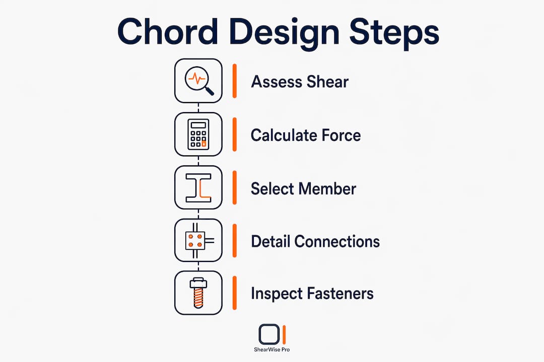
- Calculate chord force accurately. Use the diaphragm moment divided by depth. Apply load combinations from ASCE 7 for both seismic and wind.
- Verify member capacity for both tension and compression. Do not design for tension only. Compression buckling governs in many cases.
- Detail continuity at reentrant corners. Provide splice plates, straps, or welded connections that transfer both tension and compression without relying on friction.
- Address modular gaps explicitly. Gaps exceeding 1/8 inch at modular interfaces require shims or filler plates to maintain effective force transfer.
- Check rigid diaphragm requirements. Structural concrete over metal deck triggers rigid diaphragm analysis under the 2025 CBC, which must include supporting wall framing stiffness in torsional calculations.
| Design parameter | Key requirement |
|---|---|
| Chord force calculation | Diaphragm moment divided by depth; use ASCE 7 load combinations |
| Member sizing | Design for both tension and compression; check buckling |
| Continuity | Splice across all joints, corners, and modular interfaces |
| Gap tolerance | Shims or filler plates required for gaps over 1/8 inch |
| Rigid diaphragm analysis | Include wall framing stiffness when concrete topping is present |
Pro Tip: At reentrant corners, the chord force changes direction abruptly. Add a collector or drag strut at the corner to resolve the force vector cleanly before it reaches the vertical element.
Why are diaphragm chord connections critical to lateral design performance?
Fastener detailing controls diaphragm performance more than member strength in most steel deck systems. A chord member sized correctly but connected with inadequate fasteners will fail before the member reaches its design capacity. That failure mode is brittle and offers no warning.
The chord-to-deck connection transfers shear from the deck into the chord. Fastener type, spacing, and installation quality all affect the connection's strength and stiffness. Substituting a smaller fastener or increasing spacing to save time on the job site can cut connection capacity significantly.
Diaphragm chord connections often lack inherent seismic ductility. Fastener failure is the most common system-level performance issue in steel deck diaphragms. Detailing explicit load transfer mechanisms across reentrant corners and modlines is not optional in modular construction. It is a code requirement and a life-safety issue.
- Fastener type: Match fastener material and coating to the deck and chord material to prevent galvanic corrosion and ensure rated capacity
- Fastener spacing: Follow the approved fastener schedule; do not field-modify spacing without engineering review
- Installation quality: Inspect for proper seating, no over-driving, and correct angle; poor installation reduces capacity by a measurable amount
- Reentrant corner detailing: Provide explicit connection hardware at corners where chord force direction changes
- Modline connections: Detail chord splices at modular interfaces with hardware that transfers both tension and compression
Pro Tip: Specify fastener inspection as a special inspection item on the structural drawings. Diaphragm fastener installation is one of the most under-inspected elements on wood-framed and steel deck projects.
How does diaphragm chord continuity affect seismic performance?
Chord continuity is critical to seismic ductility and predictable lateral system behavior. A continuous chord allows the diaphragm to distribute inertial forces evenly to all vertical resisting elements. A discontinuous chord concentrates demand at the break point, which can cause local failure before the global system reaches its design capacity.
Performance-based design requires that the lateral system respond predictably under seismic loading. Chord continuity is the structural feature that makes that predictability possible. Without it, the diaphragm may shed load to vertical elements in an uncontrolled sequence.
Discontinuities at expansion joints, floor-to-floor interfaces, and modular building connections are the most common sources of chord continuity problems. Each requires a specific detailing solution, not a generic splice.
- Expansion joints: Provide a sliding chord splice that transfers tension and compression while accommodating thermal movement
- Floor-to-floor interfaces: Verify that the chord force path transfers through the floor framing without relying on gravity connections
- Modular interfaces: Use bolted splice plates or welded connections designed for the full chord force, not just the dead load reaction
- Reentrant corners: Add a collector element to redirect the chord force around the corner without a force discontinuity
| Discontinuity type | Consequence if unaddressed | Detailing solution |
|---|---|---|
| Expansion joint | Chord force not transferred; diaphragm splits | Sliding splice plate with full tension and compression capacity |
| Modular interface | Gap causes force transfer failure | Bolted splice plate; shims for gaps over 1/8 inch |
| Reentrant corner | Force concentration; local failure | Collector or drag strut at corner |
| Floor-to-floor interface | Load path break; code non-compliance | Explicit connection hardware through floor framing |
For full-height shear wall segment design, chord continuity at the wall-to-diaphragm interface directly controls how much of the wall's capacity the diaphragm can actually mobilize.
How to integrate diaphragm chord design into a lateral load-resisting system?
Chord connections to vertical elements must be explicitly detailed to maintain load path continuity. Assuming the chord force will find its way into the shear wall without a designed connection is a plan review failure waiting to happen. The chord must drag forces directly into the vertical element through a connection that is sized for the full chord force.
Collectors work alongside chords to complete the load path. The collector gathers shear from the deck over the length of the vertical element and delivers it to the chord or directly to the wall. Designing the chord without coordinating the collector length and capacity produces an incomplete load path.
Treating the diaphragm as an integrated system rather than isolated parts is the single most important principle in lateral design. The chord is the critical component that balances the entire load path, but it only works when the deck, collectors, and vertical elements are all designed to the same demand.
- Coordinate chord and collector design simultaneously. The collector length determines how much shear the chord receives at each vertical element.
- Detail the chord-to-shear-wall connection explicitly. Size the connection for the full chord force, not just the gravity reaction.
- Check vertical element anchorage. The shear wall or braced frame must be anchored to the foundation for the same force the chord delivers.
- Review the sheathing requirements at the wall-to-diaphragm interface. Sheathing type and fastening pattern affect how the chord force transfers into the wall panel.
- Use calculation software that tracks the full load path. ShearWise Pro organizes wall lines, hold-down forces, transfer straps, and story drift checks in one workflow, reducing the risk of missing a load path link.
Key Takeaways
Diaphragm chords are the tension and compression edge members that complete the lateral load path from deck to vertical resisting element, and their continuity, connection quality, and coordination with collectors determine whether the entire lateral system performs as designed.
| Point | Details |
|---|---|
| Chord function | Chords act as flanges of a deep beam, carrying axial tension and compression at diaphragm edges. |
| Connection controls performance | Fastener type, spacing, and installation quality govern diaphragm capacity more than member strength alone. |
| Continuity is non-negotiable | Chord discontinuities at joints, corners, and modular interfaces must be explicitly detailed for full force transfer. |
| System-level design | Chords, collectors, deck, and vertical elements must be designed together as one integrated load path. |
| Code compliance | ASCE 7 Section 12.10 requires explicit chord force calculations and documented load path continuity. |
What I've learned from years of watching chord design go wrong
The most consistent pattern I see in lateral design reviews is that engineers size the chord member correctly and then treat the connection as a standard framing detail. That assumption is where projects fail. The chord-to-deck and chord-to-wall connections are the most force-critical details in the diaphragm, and they deserve the same calculation rigor as the member itself.
Modular construction has made this worse. When two modules meet at a modline, the chord force must cross that joint through hardware that was designed, fabricated, and installed by different trades on different schedules. A gap of more than 1/8 inch with no shim is not a tolerance issue. It is a structural deficiency.
My strongest recommendation is to draw the complete load path on a single diagram before writing a single calculation. Every arrow on that diagram represents a connection that needs a number attached to it. If you cannot draw the arrow, you cannot design the connection. If you cannot design the connection, the load path does not exist.
Collaboration between the structural engineer, the architect, and the contractor is not a soft skill here. The chord splice at a modline requires the architect to locate it, the engineer to size it, and the contractor to install it with inspection. All three must be in the loop before the drawings are issued. Waiting until the field raises a question is too late.
— Evalin
ShearWise Pro and lateral load path calculations
Organizing a complete lateral load path calculation, from diaphragm chord forces through shear walls to hold-downs and foundation anchorage, requires tracking many interdependent values across multiple wall lines and stories.
ShearWise Pro is built for exactly that workflow. The platform organizes shear wall calculations by wall line, tracks hold-down forces, transfer straps, full-height segments, and story drift checks, and generates clean PDF reports for plan review coordination. For engineers and designers working on 1-story and 2-story wood-framed buildings, ShearWise Pro reduces the risk of missing a load path link by keeping every calculation in one place. Training resources and certification options are available for teams that want to build a consistent lateral design workflow.
FAQ
What is the primary role of diaphragm chords in lateral design?
Diaphragm chords are the tension and compression edge members that resist axial forces at the diaphragm boundary, transferring lateral shear from the deck to vertical resisting elements such as shear walls and braced frames.
How does chord continuity affect seismic performance?
Chord continuity allows the diaphragm to distribute inertial forces predictably to all vertical elements. Discontinuities concentrate demand at the break point and can cause local failure before the global system reaches its design capacity.
What controls diaphragm performance more: member strength or connection detailing?
Connection detailing controls diaphragm performance more than member strength. Fastener type, spacing, and installation quality at the chord-to-deck interface govern how much force the diaphragm can actually transfer.
When are shims or filler plates required at chord splices?
Shims or filler plates are required when gaps at modular interfaces or chord splices exceed 1/8 inch, to maintain effective force transfer in both tension and compression across the joint.
What code section governs diaphragm chord force requirements?
ASCE 7 Section 12.10 governs chord force calculations and load path continuity requirements for diaphragms in lateral force-resisting systems.