

The shear wall ratio is defined as the total area of lateral load-resisting shear walls divided by the building's floor area. For wood-framed structures, this ratio is a primary design parameter controlling lateral stiffness, story drift, and seismic resistance. Engineers and architects routinely confuse the area-based shear wall ratio with the aspect ratio of individual wall segments. These are two distinct values governed by different code provisions, and mixing them up introduces real design errors. Standards like SDPWS (Special Design Provisions for Wind and Seismic) and the IBC set the rules for both, and understanding what is a shear wall ratio versus what governs individual panel behavior is the foundation of any competent lateral system design.
What is a shear wall ratio, and how does it differ from aspect ratio?
The shear wall ratio and the aspect ratio of a shear wall panel are not the same metric. Confusing the two is one of the most common errors in wood-framed building design, and it directly undermines structural quality.
The shear wall ratio (also called the shear wall area ratio) measures the proportion of shear wall area to total floor area across the building. It governs global lateral stiffness and story drift control. Optimal area-to-floor ratios for buildings typically fall between 1% and 4%, with 1%–2% balancing stiffness and cost effectively for most low-rise wood construction. This ratio tells you whether the building has enough wall area overall to resist lateral loads without excessive movement.

The aspect ratio is a property of each individual shear wall segment. It is the height-to-width ratio of that panel. SDPWS limits wood structural panel aspect ratios to a maximum of 3.5:1 or 4:1, depending on sheathing type and nailing schedule. This limit exists because taller, narrower panels behave differently under shear stress and are more prone to rocking and brittle failure.
Here is how the two concepts compare at a glance:
| Parameter | Shear wall ratio | Aspect ratio |
|---|---|---|
| What it measures | Wall area / floor area | Panel height / panel width |
| Governs | Global lateral stiffness and drift | Individual panel performance and ductility |
| Typical range | 1%–4% | Max 3.5:1 or 4:1 per SDPWS |
| Code reference | IBC, SDPWS general provisions | SDPWS Section 4.3.3.2 |
| Design implication | Enough wall area in the building | Adequate panel proportions for load transfer |
Key distinctions to keep in mind:
- A building can meet its shear wall ratio target while having individual panels with non-compliant aspect ratios.
- A building can have properly proportioned panels while still being deficient in total shear wall area.
- Both parameters must satisfy code requirements independently.
Pro Tip: When reviewing a wood-framed lateral plan, check the area ratio first to confirm adequate wall coverage, then audit each segment's aspect ratio before finalizing nailing schedules and hold-down selections.
How does the shear wall ratio affect seismic performance?
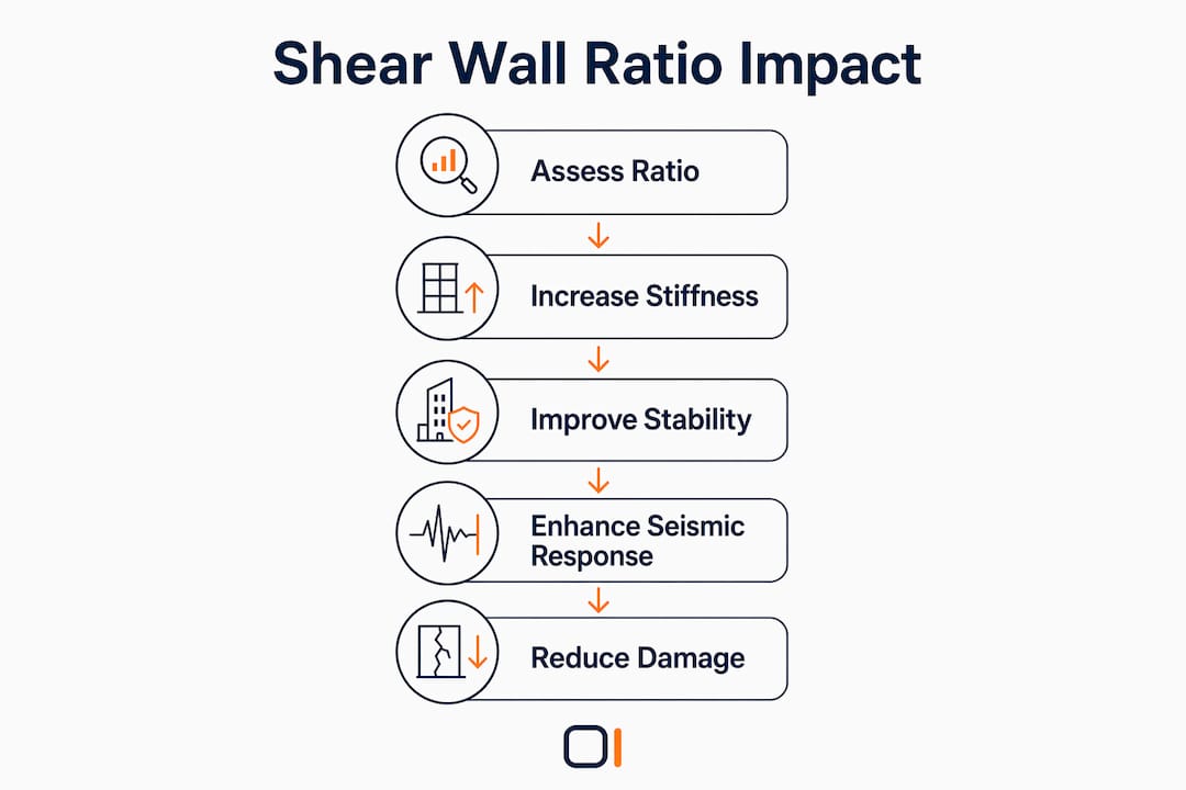
The shear wall ratio directly controls how a building responds to ground motion. A higher ratio increases lateral stiffness, which reduces story drift and limits structural damage during an earthquake. Increasing shear wall ratio reduces torsional periods by up to 55%, significantly lowering the risk of building twist in irregular structures. That is a substantial performance gain from a single design parameter.
The 1%–4% range is not arbitrary. At ratios below 1%, buildings lack the stiffness to control interstory drift within code-allowable limits. At ratios above 4%, the added wall area delivers diminishing returns on drift reduction while increasing construction cost and reducing architectural flexibility. The practical target for most 1-story and 2-story wood buildings sits in the 1%–2% range.
Distribution matters as much as total area. Symmetrical and continuous shear wall placement is required to prevent torsional irregularities, even when the overall ratio meets code. A building with all its shear walls concentrated on one side will twist under lateral load regardless of how much wall area it has.
"Over-reliance on shear wall area percentage without considering symmetry and distribution leads to poor seismic outcomes due to torsional effects. Meeting the ratio target is necessary but not sufficient for reliable lateral resistance."
The risks of improper distribution include:
- Excessive interstory drift on the under-braced side of the building
- Torsional amplification that increases forces on perimeter connections
- Concentration of damage in a single wall line during a seismic event
- Non-compliant story drift ratios that trigger code review failures
What code limits govern shear wall ratios and aspect ratios?
SDPWS is the primary standard governing shear wall design in wood-framed construction. It sets both the maximum aspect ratio for individual panels and the capacity adjustment factors that apply when panels approach those limits.
Aspect ratio capacity reductions
Nominal unit shear capacities must be reduced for wood structural panels with aspect ratios between 2:1 and 3.5:1. The reduction factor is (1.25 – 0.125 × h/b), where h is panel height and b is panel width. A panel at 3:1 aspect ratio, for example, carries only 87.5% of its nominal shear capacity. This reduction is not optional. Skipping it produces unconservative designs.
Aspect ratios greater than 2:1 require capacity adjustments to ensure ductile failure modes under seismic loading. SDPWS Section 4.3.3.2 outlines these provisions explicitly. Panels exceeding 3.5:1 are not permitted as shear wall segments under standard provisions, regardless of sheathing thickness or nailing density.
Sheathing and material requirements
Wood structural panels require a minimum sheathing thickness of 15/32 inch and APA-rated sheathing for effective load resistance under seismic and wind codes. Nailing pattern and spacing are equally critical inputs. A thicker panel with inadequate nailing does not achieve its rated capacity.
Key code considerations for wood-framed shear wall design:
- SDPWS maximum aspect ratio: 3.5:1 for standard wood structural panels (4:1 with specific conditions)
- Capacity reduction applies between 2:1 and 3.5:1 using the (1.25 – 0.125 h/b) factor
- Seismic design categories affect which wall types and connection details are permissible
- Wind load design may allow higher unit shear values than seismic design for the same panel
- Hold-down and anchor bolt requirements vary by seismic design category and story height
How to apply shear wall ratios in wood-framed building design
Applying shear wall ratios correctly requires more than calculating a percentage. The ratio is a starting point. Structural performance depends on how you distribute, connect, and detail the walls you select.
-
Calculate the required shear wall area. Determine the total lateral load from seismic or wind analysis. Divide by the allowable unit shear capacity of your chosen panel assembly to find the minimum required wall length per direction.
-
Check the area ratio. Divide total shear wall area by floor area. Confirm the result falls within the 1%–4% range appropriate for your building type and seismic design category.
-
Audit each segment's aspect ratio. For every full-height segment, compute h/b. Apply the SDPWS capacity reduction factor for any segment between 2:1 and 3.5:1. Eliminate or redesign any segment exceeding 3.5:1.
-
Distribute walls symmetrically. Place shear walls as symmetrically as possible in both plan directions. Avoid concentrating wall area on one side of the building. Use load path continuity from roof to foundation as your distribution guide.
-
Design connections before finalizing wall schedules. Shear panel capacity does not scale linearly with increased sheathing area. It is limited by anchorage and hold-down strength. Specify hold-down hardware, anchor bolts, and transfer straps before locking in your wall schedule.
-
Verify story drift. Run a drift check after placing walls. Drift limits under ASCE 7 are typically 2% of story height for wood-framed structures. Walls that satisfy the area ratio but fail the drift check require redesign.
Pro Tip: When working on 2-story wood buildings, check the shear wall ratio independently for each story. The second story often has less wall area due to window and door openings, and that deficit does not get corrected by a strong first-story ratio.
The most common mistake engineers make is adding more sheathed area without upgrading connections. Effective shear wall design manages both bending moments and shear forces, and the system is only as strong as its weakest connection. More wall area without adequate hold-downs delivers negligible additional resistance. Connection design and lateral system planning must run in parallel with ratio calculations, not after them.
Key Takeaways
The shear wall ratio is the proportion of shear wall area to floor area, and it must be evaluated alongside aspect ratio, connection design, and wall distribution to produce a code-compliant, seismically reliable wood-framed structure.
| Point | Details |
|---|---|
| Area ratio vs. aspect ratio | These are two separate metrics; both must satisfy code requirements independently. |
| Target ratio range | Shear wall area-to-floor ratios of 1%–4% control drift and stiffness in most wood buildings. |
| Aspect ratio capacity reduction | SDPWS requires shear capacity reduction for panels with aspect ratios between 2:1 and 3.5:1. |
| Distribution over quantity | Symmetrical wall placement prevents torsional failure even when the total ratio meets code. |
| Connections are the limit | Hold-down and anchor capacity, not sheathing area, sets the actual shear wall capacity. |
Why the ratio is only half the answer
After reviewing lateral designs on wood-framed projects for years, the pattern I see most often is this: engineers hit the area ratio target and stop. The ratio is green, the wall schedule looks adequate on paper, and the project moves forward. Then the hold-down schedule gets value-engineered, the walls end up asymmetrically placed to accommodate a floor plan change, and the actual seismic performance of the building drops well below what the ratio suggested.
The shear wall ratio is a useful screening tool. It tells you quickly whether a building has a reasonable amount of lateral resistance relative to its floor area. What it does not tell you is whether that resistance is connected, distributed, or detailed correctly. Shear wall ratio is a design tool, not an absolute code requirement. Effective seismic resistance depends on load path, symmetry, and connection details that no area percentage can capture.
The aspect ratio piece is where I see the second-most errors. A designer will include a 12-inch-wide panel in a 9-foot wall and count it as a shear wall segment. That panel sits at a 9:1 aspect ratio. It contributes nothing to lateral resistance under SDPWS. Catching that error requires auditing every segment, not just the total wall area.
Modern calculation tools change this dynamic. When software tracks segment dimensions, aspect ratios, hold-down forces, and drift simultaneously, you catch these errors before they reach the plan set. That is the real value of purpose-built shear wall design tools. The ratio becomes one output among many, not the final answer.
— Evalin
ShearWise Pro makes shear wall calculations faster and more accurate
Engineers and architects working on 1-story and 2-story wood buildings need a calculation workflow that handles area ratios, aspect ratios, hold-down forces, and story drift checks in one place. ShearWise Pro is built specifically for that workflow.

ShearWise Pro organizes wall lines, full-height segments, openings, transfer straps, and roof loads into a single project file. The platform applies SDPWS aspect ratio capacity reductions automatically and generates clean PDF reports ready for plan review coordination. You get accurate shear wall calculations without building a custom spreadsheet for every project. Sign up to try ShearWise Pro and run your first shear wall design in minutes.
FAQ
What is a shear wall ratio in simple terms?
The shear wall ratio is the total area of shear walls in a building divided by the total floor area. It measures whether a building has enough lateral load-resisting wall area to control drift and resist seismic or wind forces.
What is the difference between a shear wall and a shear panel?
A shear wall is the full vertical assembly that resists lateral loads, including framing, sheathing, and connections. A shear panel refers specifically to the sheathed segment within that assembly that carries the shear force.
What is a shear wall demand-capacity ratio?
The shear wall demand-capacity ratio compares the actual lateral load demand on a wall segment to its code-allowable shear capacity. A ratio at or below 1.0 indicates the wall segment is adequate; a ratio above 1.0 means the segment is overstressed and requires redesign.
What is a cantilever shear wall?
A cantilever shear wall is a wall segment that resists lateral loads through bending and shear without a hold-down at its base, relying instead on its own weight and anchorage for overturning resistance. This configuration is less common in wood-framed residential construction and requires careful drift analysis.
What is the maximum aspect ratio for a wood shear wall panel?
SDPWS limits wood structural panel shear wall segments to a maximum aspect ratio of 3.5:1 under standard provisions. Segments between 2:1 and 3.5:1 require a capacity reduction using the factor (1.25 – 0.125 × h/b).