
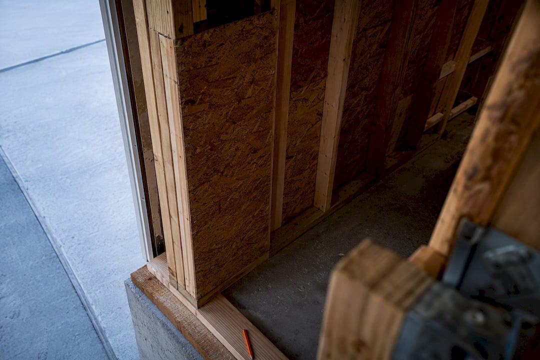
Under the IRC prescriptive method, required wall bracing is calculated per braced wall line using Table R602.10.3 and adjusted for wind speed, seismic design category, and exposure. A braced wall panel is a prescriptive, code-defined segment; an engineered shear wall is designed for site-specific loads when prescriptive limits are exceeded. Start by locating every braced wall line on your plan and pulling the wind, seismic, and exposure inputs before you touch a table.
TL;DR:
- When wind speeds reach 140 mph or seismic design category E, the prescriptive bracing method is insufficient and engineered shear walls are required.
- Continuous sheathing methods generally require less bracing length than intermittent panel methods, making them more efficient for tight layouts.
- Adjustments for interior gypsum finish, blocked joints, exposure category, and building height can significantly alter the required bracing length, so these factors must be carefully verified.
- Properly locating braced wall lines, accurately sizing hold-downs, and cross-checking calculations against construction documents are key to passing plan review without delays.
- Using dedicated software like ShearWise Pro can streamline calculations, ensure code compliance, and produce review-ready reports, but correct input selection remains essential.
Table of Contents
- What the IRC Prescriptive Braced Wall Method Covers
- Nine IRC Bracing Methods, Ranked by Efficiency
- How to Compute Required Bracing for a Braced Wall Line
- Gypsum, Blocking, Exposure, and Height: The Adjustment Factors That Move the Number
- Narrow-Panel and Alternate Bracing Methods for Tight Layouts
- Hold-Downs and the Uplift Load Path
- Plan-Review Checklist: What Reviewers Expect to See
- Worked Example: A Two-Story Wood-Framed Residence
- Calculators, Compliance, and What to Look for in a Tool
- Practitioner Perspective: Frequent Plan-Review Mistakes and How Teams Avoid Them
- Try ShearWise Pro: Free Trial, Sample Reports, and Tutorials
- Sources
- FAQ
What the IRC Prescriptive Braced Wall Method Covers
The IRC draws a firm line between two design paths, and knowing which one you're on determines everything downstream. A braced wall panel is a section of wall, built with a specific IRC-recognized method, that resists lateral forces without site-specific engineering calculations. A braced wall line is the row those panels sit on, running the length of a wall or a defined offset from it. These definitions come straight from R202 and R602.10, and they matter because the whole prescriptive system depends on measuring bracing along that line, not wall by wall.
A shear wall, by contrast, is an engineered element. It's designed under principals of structural mechanics, typically per IBC or referenced standards like ASCE 7 and the National Design Specification for wood, with calculated capacities tied to actual loads rather than a table lookup. Shear walls show up when a project falls outside what the IRC's prescriptive tables cover, or when an engineer of record simply prefers full design control over a lateral system.
That handoff point isn't arbitrary. The IRC explicitly caps how far its prescriptive provisions reach:
- Ultimate design wind speeds at or above 140 mph generally falls outside the prescriptive bracing tables and requires engineered design.
- Buildings in Seismic Design Category E, or certain conditions within higher SDC assignments, exceed what the standard bracing tables were built to handle.
- Special wind regions, unusual topography, or irregular building geometry (large re-entrant corners, cantilevered floors, tall narrow footprints) often push a project past prescriptive limits even when wind speed and SDC look manageable on paper.
- Buildings taller than the IRC's story and height limits for wood-framed construction need an engineered lateral system regardless of wind or seismic inputs.
When any of these conditions apply, stop reaching for R602.10 tables and call for an engineered shear wall design instead. Trying to force a high-wind or high-seismic project into prescriptive bracing is one of the fastest ways to generate a plan review rejection, and worse, a real structural liability. For a deeper breakdown of when that handoff happens, see our comparison of IRC bracing methods and engineered shear walls.
Nine IRC Bracing Methods, Ranked by Efficiency
The IRC recognizes a defined set of bracing methods, and each one earns a different amount of "credit" toward your required bracing length. Knowing which methods are efficient and which eat up wall space is half the battle in laying out a workable floor plan.
Here's the standard catalog, from least to most efficient in terms of length required to meet a given bracing demand:
- LIB (Let-In Bracing): diagonal 1x4 boards let into studs; low capacity, rarely used in modern construction but still code-recognized.
- DWB (Diagonal Wood Boards): diagonal sheathing boards nailed directly to framing; another legacy method with modest capacity.
- WSP (Wood Structural Panel), often called Method 3: plywood or OSB sheathing nailed to studs; this is the workhorse method in almost every modern IRC-compliant house.
- GB (Gypsum Board): gypsum wallboard nailed or screwed to framing; low capacity per foot but useful as a supplemental or interior-side method.
- SFB (Structural Fiberboard): fiberboard sheathing panels; uncommon today but still tabulated.
- PBS (Particleboard Sheathing): similar role to WSP but with lower allowable capacity.
- PCP (Portland Cement Plaster): stucco-based bracing, common in some southwestern markets.
- HPS (Hardboard Panel Siding): exterior hardboard siding nailed per code spacing.
- CS-WSP / CS-G (Continuous Sheathing methods): wood structural panels applied continuously across the entire wall height and length of a braced wall line, not just at panel locations; these generally require less total length to satisfy the same bracing demand than intermittent methods.
Continuous sheathing methods (the CS variants) typically outperform intermittent WSP bracing on a length-for-length basis, which is why so many production builders default to full OSB sheathing on every exterior wall rather than isolating specific 48 inch panels. Minimum individual panel widths vary by method and by whether you're using standard or narrow-panel allowances, generally running from 16 inches up to 48 inches or more depending on wall height and the alternate method selected.
Partial credit rules also come into play when panels don't meet full minimum width. The APA guide to the 2015 IRC wood wall bracing provisions walks through how mixing methods along a single braced wall line is permitted under specific conditions, which gives designers real flexibility when a floor plan has awkward window and door placement that won't accommodate full-width panels everywhere.
How to Compute Required Bracing for a Braced Wall Line
Calculating required bracing isn't a single lookup. It's a sequence, and skipping a step is exactly how designers end up under-braced on a wall line that looked fine on a quick glance.
- Gather your site and building inputs. Pull the ultimate design wind speed from Figure R301.2(4), confirm the seismic design category, determine the exposure category (B, C, or D), and note wall height and total story count for the structure.
- Establish braced wall lines on the plan. Mark every required line, typically at the building perimeter and at specified interior spacing, then measure each line's total length.
- Check spacing and end-distance rules. The IRC limits how far apart braced wall panels can sit along a line and how far the first panel can sit from a line's end; violating these limits is one of the most common reasons plans bounce back from review, according to code compliance guidance for wall bracing.
- Select your bracing method or methods. Choose from the catalog above based on architectural constraints, then look up the base required amount in Table R602.10.3(1) through (4), matched to your wind speed, SDC, and story location.
- Apply adjustment factors. Exposure category, gypsum board on the interior face, blocked horizontal joints, and the option to average braced wall line spacing all shift the required length up or down.
- Total it up per story. Compare total required bracing length against what your layout actually provides, and document any hold-downs or connector details tied to specific panels.
Statistic Callout: Required bracing percentages under the IRC's tables vary with wind speed and seismic design category, generally increasing from moderate amounts in low-wind, low-seismic areas up to higher amounts in more demanding conditions, according to technical guidance on wall bracing compliance. That spread is exactly why pulling the wrong exposure category or wind speed at step one can throw off your entire panel count.
Pro Tip: Run your wind speed and SDC lookup before you sketch a single panel location. Adjusting a layout after the fact because your inputs changed wastes more time than confirming them up front ever costs you.
Gypsum, Blocking, Exposure, and Height: The Adjustment Factors That Move the Number
Base table values rarely stay as-is once you apply the modifiers the IRC requires or permits. Each adjustment either tightens or loosens your required bracing length, and missing one is a common source of under-bracing that plan reviewers catch immediately.
Gypsum board on the interior face of a braced wall line can reduce the required length of wood structural panel bracing, but the reduction differs depending on whether gypsum is applied to one side or both sides of the wall. Double-sided gypsum application generally earns a larger adjustment than single-sided, and the code spells out the specific percentage reduction tied to each condition.
Blocked horizontal joints in wood structural panel sheathing are mandatory for certain bracing methods and wind or seismic conditions, and they change the base capacity assigned to that panel. Skipping blocking where it's required doesn't just risk a field correction, it invalidates the bracing credit you assumed in your calculation.
Exposure category shifts the wind pressure the structure has to resist. Exposure C and D generally require more bracing length than Exposure B for the same wind speed, since the unobstructed terrain assumed under those categories drives higher design pressures.
- Confirm gypsum credit only where the interior finish is actually specified and installed to match your assumption.
- Verify blocking requirements before finalizing panel schedules, not after framing starts.
- Recheck exposure category against the actual site condition, not a default assumption carried over from a previous project.
- Note that stone or masonry veneer adds weight and can influence wall height limitations and connection detailing tied to bracing panels.
Statistic Callout: Moving from Exposure B to Exposure C can meaningfully increase required bracing length for the same wind speed and wall configuration, which is one reason two houses with identical footprints on different sites can carry very different bracing schedules.
Narrow-Panel and Alternate Bracing Methods for Tight Layouts
Large window walls and garage door openings routinely eat up the wall length a designer needs for standard bracing panels. The IRC accounts for this with a set of alternate, narrower methods that trade simplicity for stricter detailing requirements.
ABW (Alternate Braced Wall panel) allows a narrower panel, often as little as 28 to 32 inches wide depending on wall height, in exchange for specific hold-down and anchorage requirements at each end of the panel. PFH (Portal Frame with Hold-downs) and PFG (Portal Frame at Garage door openings) go even further, using engineered header and hold-down assemblies to brace narrow wall segments beside garage doors, one of the toughest layout challenges in residential design.
- ABW panels require full-height sheathing, specific nailing schedules, and hold-downs capable of resisting calculated uplift forces at both ends.
- PFH and PFG assemblies are proprietary or code-prescribed portal systems, generally limited to specific header sizes and story-height conditions.
- Mixing narrow-panel methods with standard WSP bracing on the same line is permitted under IRC rules, but each method's specific requirements still apply independently.
- Story height limits and specific hold-down hardware requirements mean these methods aren't a free pass around bracing minimums, they're a trade of width for detailing complexity.
Continuous sheathing methods often solve the same layout problem with less complexity, since they distribute capacity across the whole wall rather than concentrating it in a narrow, heavily-detailed segment. When a garage door opening or a bank of windows pushes you toward three or four narrow panels stacked with hold-downs, it's worth checking whether switching the rest of that wall line to continuous sheathing reduces your total required length enough to simplify the whole elevation.
Pro Tip: Before committing to a portal frame at a garage opening, check whether extending continuous sheathing on the adjacent wall segments gets you to your required bracing total without the extra hardware. It often does, and it's a simpler detail for the framing crew to execute correctly.
Hold-Downs and the Uplift Load Path
Braced wall panels don't just resist lateral shear, they also have to resist uplift, and the IRC assumes panels handle both forces unless a separate, continuous uplift path is engineered into the structure. That assumption is exactly why hold-down requirements show up wherever net uplift forces exceed specific thresholds tied to wind speed, wall height, and the bracing method selected.
Hold-down triggers generally show up in a few predictable places:
- Alternate braced wall panels (ABW) and portal frame methods (PFH, PFG) almost always require hold-downs at panel ends by definition of the method itself.
- Standard WSP panels can also require hold-downs when calculated uplift, based on wind speed and tributary wall area, exceeds the capacity of standard framing connections alone.
- Higher wind speeds and taller wall heights push more panels into the hold-down-required category, even when the same panel wouldn't need one in a lower-wind location.
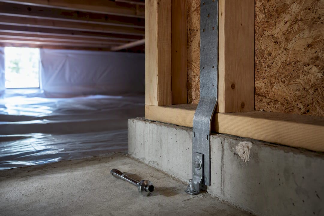
Reports and calculator outputs typically present hold-down requirements as a specific force value, in pounds, tied to each panel location, along with a recommended hardware type or capacity rating. That force value then drives hardware selection, whether that's a strap-type hold-down, a mechanical hold-down device, or a continuous rod system running through multiple stories.
Detailing the connection correctly matters as much as calculating the force. Anchor embedment into the foundation has to match the hold-down manufacturer's tested capacity, straps need to maintain continuity through the top plate without interruption from blocking or utility penetrations, and multi-story buildings need the uplift path to run continuously from roof to foundation, not just floor to floor. A hold-down force calculated correctly but detailed with the wrong embedment depth or an interrupted strap path still fails the load path requirement on inspection.
Plan-Review Checklist: What Reviewers Expect to See
A permit reviewer looking at a braced wall submission checks for specific, predictable information, and missing any one item is a common source of review comments that delay a permit by weeks.
Your plans should clearly show: braced wall line locations, panel positions and widths at each location, the bracing method assigned to each panel, the contribution value that method provides toward the required total, and hold-down or connector details wherever they apply.
- Label every braced wall line explicitly, not just implied by wall location.
- Show panel width dimensions directly on the plan, not buried in a calculation sheet.
- Note the bracing method per panel using standard code abbreviations (WSP, CS-WSP, ABW, and so on).
- Include a summary table per story showing total required bracing versus total provided.
- Call out gypsum assumptions explicitly if you're taking credit for interior finish.
- List every hold-down location with its required capacity and specified hardware.
| Common Red Flag | Why Reviewers Flag It |
|---|---|
| Missing end-distance dimensions | Reviewers can't confirm panel placement meets spacing limits |
| Gypsum credit assumed but not specified in finish schedule | Creates a mismatch between calculation and construction documents |
| Hold-down hardware omitted from panel schedule | Uplift path can't be verified without a specified connector |
| No story-by-story bracing summary | Reviewers have to reconstruct totals manually, slowing approval |
| Bracing method not labeled on plan | Ambiguity forces a reviewer to guess or request clarification |
A story-by-story summary table, listing required percentage or length against provided length for each braced wall line, is the single fastest way to reduce back-and-forth with a reviewer. It's also exactly the kind of output a well-built layout checklist or calculator report generates automatically.
Worked Example: A Two-Story Wood-Framed Residence
Here's how the calculation plays out on a representative project: a two-story wood-framed house, 140 mph is not the assumption here, we'll use a more typical suburban condition of 115 mph ultimate design wind speed, Seismic Design Category C, Exposure B, with 9 foot wall heights on both stories.
- Confirm inputs. Wind speed 115 mph, SDC C, Exposure B, two stories, 9 foot wall height each level.
- Identify braced wall lines. The example home has four exterior braced wall lines and one interior line running through the center of the plan, with the longest exterior line measuring a typical length used for example calculations.
- Check spacing. Interior braced wall lines under IRC 2024 R602.10 generally can't exceed roughly 35 feet of spacing for many buildings, confirming the interior line placement is required, not optional.
- Look up base required bracing. For the first-story bottom wall line under these wind and SDC inputs, Table R602.10.3(1) yields a base required bracing percentage in the lower to mid range applicable to that site and bracing method, applied to the 42 foot line length.
- Apply adjustments. The design includes single-sided gypsum on the interior face and unblocked panel joints, so the applicable gypsum credit applies but no blocking credit is available; Exposure B requires no upward adjustment.
- Compute the required length. After applying gypsum adjustment, the required bracing length corresponds to a portion of the 42 foot line that meets code for that wind and seismic condition with WSP panels.
- Lay out panels to meet or exceed that total. The designer places three 48 inch WSP panels (12 feet total) plus one 24 inch panel, reaching 14 feet of provided bracing, satisfying the requirement with a small margin.
The permit-ready summary attached to a submission like this shows each braced wall line by name, its measured length, the required and provided bracing figures, the method selected, and any hold-down locations tied to narrow panels or portal assemblies. A sample report built in this format gives reviewers everything they need in one glance instead of forcing them to reconstruct the math from scattered plan notes.
Calculators, Compliance, and What to Look for in a Tool
A validated calculator handles the repetitive arithmetic correctly every time: braced wall line totals, the average-spacing option, hold-down sizing, and formatted report generation. What it can't do is replace your understanding of the underlying code, since every input still has to be selected correctly by the person running the tool.
When evaluating a calculator for IRC compliance work, check these items before trusting it on a real project:
- Confirm which IRC code edition the tool supports, since bracing tables and adjustment factors have changed across editions.
- Verify table fidelity against the actual R602.10 tables rather than assuming the tool's internal logic matches the code exactly.
- Check whether the exported report format includes the story-by-story summary, hold-down schedule, and method labeling a plan reviewer expects.
- Confirm the output is editable enough to add project-specific notes or revise inputs without starting over.
Some software platforms are built around this workflow for 1 and 2-story wood-framed buildings, organizing wall lines, tracking openings and full-height segments, calculating hold-down forces and transfer strap requirements, checking story drift, and producing clean PDF reports formatted for review coordination. Rather than reconstructing a bracing summary by hand for every revision, you update inputs and regenerate the report, with tutorials available to walk through the specific workflow for wall line setup, opening entry, and hold-down output.
Practitioner Perspective: Frequent Plan-Review Mistakes and How Teams Avoid Them
The mistakes that keep showing up in plan review aren't complicated ones. They're small oversights: a gypsum credit assumed but never confirmed against the finish schedule, a hold-down noted in a calculation but left off the framing plan, an end-distance dimension nobody double-checked against the actual door swing.
One recurring scenario involves a narrow wall segment beside a garage opening, where a portal frame hold-down was calculated correctly but never made it onto the sheathing schedule sent to the framer. The wall got built without it. That gap surfaced during a later inspection, well after the framing was closed in, turning a five-minute detailing fix into a costly rework.
Teams that avoid this build a habit of cross-checking the calculation summary against the actual construction documents before submission, not after a review comment forces the issue. Treating the bracing calculation and the framing plan as two documents that must agree, rather than one feeding the other loosely, catches these gaps before they reach a job site.
— Evalin
Try ShearWise Pro: Free Trial, Sample Reports, and Tutorials
Some software converts the manual table lookups and hand-built summaries covered above into a structured workflow designed for 1 and 2-story wood-framed projects. Instead of tracking braced wall lines, openings, hold-down forces, and transfer straps across spreadsheets and separate calculation sheets, users can organize the whole project in one place and export a clean PDF report ready for review coordination.

The platform includes story drift checks alongside your bracing calculations, so you're not running a separate analysis to confirm your structure meets both requirements. A free trial gives you three watermarked reports to test the workflow against a real project before committing to a subscription, and the sample report shows exactly what a finished submission looks like before you generate your first one. Review the tutorials to see the wall line and hold-down entry process in action, then start your own project on the ShearWise Pro shear wall calculator. As with any prescriptive calculation, confirm local code amendments and specific requirements with your authority having jurisdiction before final submission.
Sources
Verify calculations against primary sources before submitting for permit. Start with IRC Chapter 6, Section R602.10 for the code text itself, the APA guide to wood wall bracing provisions for layout and mixing-methods guidance, and the Simpson Strong-Tie wall-bracing calculator tutorial for how proprietary panel calculations get applied in practice. Always cross-check against your jurisdiction's specific code amendments.
- CHAPTER 6 WALL CONSTRUCTION - IRC 2024 (ICC)
- A guide to the 2015 IRC wood wall bracing provisions (APA)
FAQ
What Is the IRC Braced Wall Method?
It's the prescriptive system under IRC Section R602.10 that determines required wall bracing amounts using code tables, based on wind speed, seismic design category, and building configuration, without requiring individualized structural engineering.
How Is IRC Braced Wall Different From an Engineered Shear Wall?
A braced wall panel meets prescriptive code requirements from standardized tables, while an engineered shear wall is calculated for site-specific loads by a licensed engineer, typically required when wind speeds, seismic conditions, or building geometry exceed prescriptive limits.
What Are the Main IRC Bracing Methods?
The IRC recognizes methods including LIB, DWB, WSP, GB, SFB, PBS, PCP, HPS, and continuous sheathing variants (CS-WSP, CS-G), plus alternate methods like ABW, PFH, and PFG for narrow wall segments.
When Do I Need Hold-Downs on a Braced Wall Panel?
Hold-downs are required when calculated uplift forces exceed standard connection capacity, which happens by default with alternate braced wall panels and portal frame methods, and can also apply to standard WSP panels at higher wind speeds or taller wall heights.
Can a Calculator Like ShearWise Pro Replace Manual IRC Bracing Calculations?
A calculator like ShearWise Pro automates the table lookups, adjustment factors, and report formatting involved in IRC bracing calculations, but the designer still needs to select the correct wind speed, seismic design category, and exposure inputs for accurate results.