
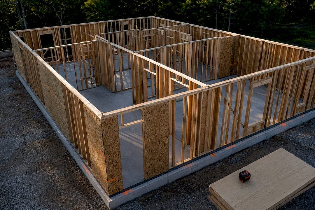
A compliant shear wall layout creates continuous braced wall lines that transfer lateral loads to the foundation without excessive torsion, and it does so within limits set by the IRC, ASCE 7, AWC SDPWS, and (for concrete) ACI 318. The plan-level rules that matter most are offset limits, maximum panel spacing, and where collectors and hold-downs pick up the load path. Get those three right and most layouts pass review on the first submission.
TL;DR:
- Most typical wood-framed houses can comply with IRC prescriptive rules if offset, spacing, and load path requirements are met; larger or irregular structures require engineered design.
- Offsets beyond 4 feet from the braced wall line disqualify panels from counting toward the same line, and spacing over 25 feet generally needs additional adjustments or engineering.
- Proper shear wall layout involves identifying all braced lines, placing panels accordingly, and ensuring cumulative bracing length meets demand based on wind and seismic factors.
- Continuous sheathing, properly designed collectors, and hold-downs are critical to maintaining load path integrity from roof to foundation.
- Automated tools like ShearWise Pro extract calculations for bracing length, forces, and drift, streamlining review-ready documentation and reducing redesign risks.
Table of Contents
- Which Codes Govern Shear Wall Layout, and When Do They Apply?
- Braced Wall Lines and Panels: The Placement Rules That Actually Matter
- From Schematic Plan to Verified Bracing: The Layout Workflow
- Sheathing, Collectors, and the Load Path That Ties It Together
- An Engineer-Ready QA Checklist Before You Submit
- A Worked Example and the Mistakes That Keep Repeating
- Coordination Trade-Offs That Save a Redesign
- Where ShearWise Pro Fits Once the Layout Is Set
- Sources
Which Codes Govern Shear Wall Layout, and When Do They Apply?
Most 1- and 2-story wood-framed houses fall under the International Residential Code, which handles wall bracing through prescriptive tables rather than full structural analysis. Once a building exceeds IRC scope, taller structures, unusual geometry, or heavier occupancy, you shift to the IBC, which points to ASCE 7 for lateral load determination and to the AWC SDPWS for wood shear wall design values. Concrete shear walls follow ACI 318 provisions for in-plane shear, flexure, and reinforcement detailing.
The IRC's prescriptive path only works if your layout stays inside a handful of limits:
- Braced wall panels must start within a set distance of the braced wall line's end.
- Adjacent panel edges can't exceed the code's maximum clear spacing.
- Each braced wall line needs a minimum cumulative bracing length based on wind and seismic demand.
These limits aren't arbitrary. Braced wall line spacing typically caps out at 25 feet on center, though some jurisdictions allow up to 35 feet for constrained single-room cases if you apply the required adjustment multipliers. Push past that spacing without the adjustment, and your reviewer will kick the plan back.
You move to engineered design when the prescriptive tables can't absorb your geometry: tall walls, large window openings clustered together, plan irregularities that create torsion, or simply a building type outside IRC scope. Engineered layouts need a full ASCE 7 lateral analysis, sealed calculations, and documented collector and top-plate capacity. Expect your permit set to include a lateral load summary, braced wall line diagrams with dimensioned panel locations, and hold-down schedules, not just a note referencing "code minimum bracing."
Braced Wall Lines and Panels: The Placement Rules That Actually Matter
A braced wall line (BWL) is the code's shorthand for a plane of lateral resistance, typically running along an exterior wall or a major interior partition. A braced wall panel (BWP) is the actual sheathed segment that does the work within that line. The two aren't always the same thing, and mixing them up is where a lot of layouts go wrong.
Here's the rule that trips people up most often: the IRC allows a panel located up to 4 feet from the designated braced wall line to still count as part of that line. Offset it more than 4 feet, and you can't credit it to the same BWL anymore. That single dimension shapes how you handle bump-outs, staggered exterior walls, and interior partitions that don't quite line up with the exterior plane.
Beyond the offset rule, three placement checks govern every layout:
- Start distance. Panels generally need to begin within roughly 10 to 12.5 feet of the braced wall line's end, depending on the bracing method used.
- Maximum clear gap. Adjacent panel edges can't exceed the method-specific spacing limit, commonly 20 to 25 feet on center.
- Minimum panel count and length. Each BWL needs enough cumulative sheathed length to meet the table value for your wind speed, seismic design category, and story height.
Symmetry does more work than most designers give it credit for. Distributing panels evenly across both directions, adding an interior BWL where the exterior line falls short, and favoring continuous sheathing over scattered short segments all reduce eccentricity before you ever run a torsion check.
Pro Tip: When an offset partition sits just outside the 4-foot window, don't fight it. Treat it as its own interior braced wall line instead of forcing a code exception. It's usually faster to add bracing length there than to argue geometry with a plan reviewer.
From Schematic Plan to Verified Bracing: The Layout Workflow
A workable shear wall layout follows the same sequence every time, whether you're sketching by hand or working inside a calculator platform.
- Identify braced wall lines on the schematic plan, both exterior and any required interior lines.
- Choose a bracing method (or methods) for each line based on the IRC table or, for engineered walls, the AWC SDPWS design values.
- Calculate required bracing length per BWL using wind speed, seismic design category, story count, and wall height inputs.
- Place panels and check start distance, maximum clear spacing, and the 4-foot offset rule against the schematic.
- Design collectors, top plate splices, and hold-downs wherever panel spacing widens or an opening interrupts a line.
- Run drift and torsion checks for anything outside prescriptive scope, then document every deviation.
Steps 1 through 4 are largely table lookups. That's what makes IRC bracing efficient for typical wood construction, you're checking dimensions against published limits, not running a full analysis. Steps 5 and 6 are where judgment and calculation converge, particularly torsion and story drift, which usually need dedicated software or a spreadsheet workflow built specifically for lateral analysis.
Permit reviewers want to see the same documentation regardless of method: dimensioned BWL diagrams, panel lengths called out on the plan, hold-down and strap schedules, and a clear note distinguishing prescriptive bracing from engineered lateral design.
Sheathing, Collectors, and the Load Path That Ties It Together
A shear wall layout only works if the load path stays continuous from roof diaphragm to foundation. That continuity depends on sheathing method, collector design, and connection hardware, details that live one level below the plan-level rules but decide whether the layout actually performs.
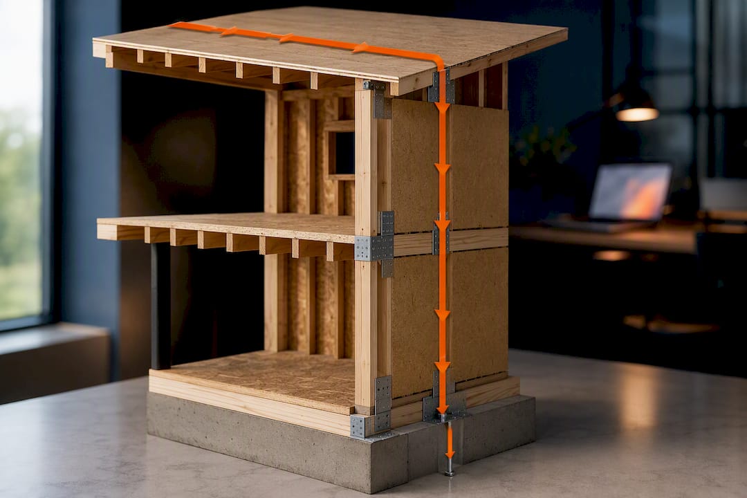
Braced wall panels are full-height sheathed sections, typically capped around 12 feet, that resist wind and seismic loads. Continuous sheathing runs the full length of a wall with openings framed into it; intermittent sheathing uses separate full-height segments between openings. Continuous sheathing generally counts differently than intermittent methods in the bracing tables, and interior finishes like half-inch gypsum can affect which methods qualify without added adjustment factors.
Wider panel spacing puts more demand on the pieces connecting everything:
- Collectors and top plate splices need enough capacity to gather force from unbraced wall segments and deliver it into the nearest panel, this becomes critical once spacing approaches the code maximum.
- Hold-downs resist overturning at panel ends and need a continuous connection down to the foundation, not just a bracket at the sill.
- Transfer straps and anchor bolts complete the path at the foundation and at floor-to-floor transitions in multi-story buildings.
The most common pitfall shows up at foundations, where anchor bolt spacing gets specified without checking it against actual hold-down demand, and at openings, where a collector gets sized for the wrong tributary length. Coordinating nailing schedules with your sheathing choice early avoids a redesign after framing starts.
An Engineer-Ready QA Checklist Before You Submit
Run this sequence before the layout leaves your desk. It catches the errors that cause the most permit delays.
- Confirm every braced wall line is identified on the plan, exterior and interior.
- Verify no panel sits more than 4 feet off its designated BWL.
- Check start distance and maximum clear gap for every panel against the code table.
- Confirm cumulative bracing length meets or exceeds the required value per line.
- Verify drift and torsion checks for any line outside prescriptive scope.
- Confirm collector and top plate splice capacity at every wide-spacing condition.
- Verify hold-down, strap, and anchor bolt schedules match the calculated demand.
- Attach sealed calculations and manufacturer evaluation reports for any engineered or proprietary system.
Flag anything that fails steps 2, 3, or 5 immediately, those are the red flags (plan eccentricity, an unsupported long wall run, or two incompatible bracing methods meeting at a corner) that force a redesign rather than a quick note revision.
Pro Tip: Keep a running log of every engineered exception on the plan itself, not just in your calculation package. Reviewers move faster when the deviation and its justification are visible right where the geometry looks unusual.
A Worked Example and the Mistakes That Keep Repeating
Take a simple one-story wood-framed rectangle. Mark the two exterior BWLs on the long walls, confirm no interior partition needs to serve as a third line, then place panels at each corner and check that clear spacing between them stays under the code maximum. Add up panel lengths per line and compare against the required bracing length for your wind and seismic inputs, if it falls short, add length before you add hardware.
Multi-story and taller buildings raise the stakes: torsion and load path continuity between stories become the driving concerns, and layout optimization studies show that computational approaches can cut structural weight by close to 14% compared with conventional layouts in tested cases.
Common mistakes worth flagging early:
- Misreading a BWL end as a random point instead of an intersection with a perpendicular line or a real wall.
- Ignoring the 4-foot offset rule when a partition doesn't quite align with the exterior plane.
- Sizing a collector for the opening width instead of the full tributary length it collects.
- Skipping the adjustment multiplier when BWL spacing exceeds 25 feet under an exception case.
Coordination Trade-Offs That Save a Redesign
A window shifted two feet can eliminate a collector entirely. That's the trade-off worth raising with architects before floor plans lock: small layout shifts near braced wall lines often cost less than the hardware needed to work around them. Flag MEP penetrations and foundation anchorage near every BWL early, and request an engineered alternative the moment torsion or an unusual opening pattern shows up, not after framing starts.
— Evalin
Where ShearWise Pro Fits Once the Layout Is Set
Once you've marked your braced wall lines and checked offsets, spacing, and start distances by hand, the next bottleneck is usually the math: cumulative bracing length per line, hold-down forces at each panel end, transfer strap sizing, and story drift checks across every load case. This work can be organized in one place instead of across scattered spreadsheets.

The platform lets you input wall lines and openings, then calculates cumulative bracing length, hold-down forces, transfer straps, and drift checks automatically, producing a clean PDF report ready for permit review. What normally takes a full afternoon of spreadsheet cross-checking compresses into a workflow you can finish before lunch, with far less risk of a missed spacing limit or an uncoordinated collector. For an overview of core features, the shear wall calculator software page and the tutorial library cover wall line setup and report generation step by step. A free trial includes a limited number of watermarked reports to evaluate the tool before subscribing. Sign up to try ShearWise and see how your next layout holds up.
Sources
- IRC 2024, Chapter 6 — Wall construction
- IRC wall bracing code compliance guide for builders, designers, and plan reviewers
- Classic wall bracing (Fairfax County guidance)
- Shear wall layout optimization using ESO and case studies