

In shear wall design, "lumber checking" refers to the full set of structural verifications you run on wood-framed walls: shear capacity, hold-down sizing, anchor bolt demands, transfer strap forces, opening geometry, and story drift. This is not about seasoning cracks or moisture content. It is the systematic review that confirms your lateral system carries load from the roof diaphragm to the foundation without a gap in the load path.
TL;DR for practicing engineers:
- Collect wall line layout, tributary diaphragm loads, and governing wind or seismic case before any calculation starts.
- Verify unit shear capacity for each wall segment against SDPWS tables or WFCM lookups.
- Size hold-downs from overturning demand at every wall end; confirm anchor bolt embedment and plate washers.
- Check collector continuity and strap development length at every opening.
- Compute story drift and compare to the allowable limit per SDPWS and IBC provisions.
Table of Contents
- What does this lumber-checking guide cover?
- Step-by-step lumber-checking workflow for every job
- Key element checks: sheathing, hold-downs, straps, and openings
- When should you use WFCM vs. SDPWS?
- Most frequent errors in shear wall checks and how to prevent them
- What goes into a permit-ready lumber-checking report?
- Worked example: lumber checking for a 1-story wood residence
- Tools and templates that speed up your lumber checks
- Key Takeaways
- How a practicing engineer actually runs lumber checks
- ShearWise Pro puts your lumber checks in one place
- Key references for permit documentation
What does this lumber-checking guide cover?
This guide covers structural checks for wood-framed shear walls in 1- and 2-story U.S. residential buildings. Every section maps to permit-submission requirements.
Included topics:
- Shear capacity checks per SDPWS and WFCM
- Hold-down and anchor bolt sizing
- Transfer strap and collector design
- Opening geometry and aspect ratio adjustments
- Story drift and deflection verification
- Permit-ready reporting items
Explicitly excluded: wood seasoning, milling defects, kiln-drying guidance, and moisture-related lumber quality assessment. Those are separate disciplines with a different audience.
Governing documents referenced throughout: AWC SDPWS, WFCM, IBC Chapter 23, APA technical notes, and WoodWorks guidance.
Pro Tip: Save the governing code edition and jurisdiction in your project header before any calculation. A reviewer who cannot confirm your code basis will flag the report immediately.
Step-by-step lumber-checking workflow for every job
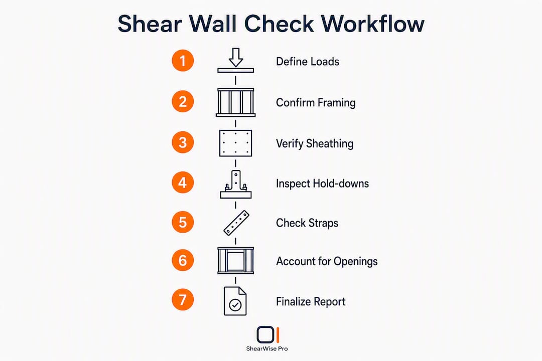
Follow this sequence from model inputs to final verification. Skipping steps is where rework originates.
- Calculate design shear per wall line. Distribute the diaphragm shear to each wall line based on tributary area (flexible diaphragm) or relative stiffness (rigid diaphragm). See wall line shear distribution methods for the full procedure.
- Determine wall segment capacities. Look up allowable unit shear values from SDPWS tables or WFCM based on sheathing, nail schedule, and framing spacing. Apply species adjustment factors where required.
- Summarize and document — Record all assumptions, table references, and code sections in the calculation appendix.
Quick check snippet: For a 10-ft-tall wall segment carrying 400 plf unit shear with C₀ = 1.0, hold-down demand T = 400 × 10 / 1.0 = 4,000 lb. Confirm the selected device's published allowable load exceeds that value before moving on.
Pro Tip: Name every wall line with a consistent label (e.g., A1-N, A1-S) from the first calculation sheet. Inconsistent naming between the plan and the calc appendix is one of the most common reviewer comments on residential submittals.
Key element checks: sheathing, hold-downs, straps, and openings
Each element below carries a specific verification step. Missing one breaks the load path.
Sheathing and fastener schedule

Verify panel type (OSB or plywood), minimum thickness, nail diameter, and edge/field spacing against SDPWS Table 4.3A or the applicable WFCM table. Fastener schedule selection directly controls allowable unit shear. Apply the species adjustment factor when framing is not Douglas Fir-Larch or Southern Pine.
Hold-downs and anchor bolts
Check required uplift at each wall end. Confirm bolt diameter, embedment depth into the foundation, and plate washer size. WoodWorks guidance identifies improper hold-down and transfer strap detailing as a leading source of design errors in wood-frame lateral systems.
Transfer straps and collectors
Collectors must run the full length of the force-transfer shear wall. Metal straps at openings, however, only need to be long enough to develop the induced corner forces. WoodWorks clarifies that straps are not required to extend the full wall length when designers provide alternate collectors or transfer diaphragms. Confusing straps with collectors is a frequent detailing error.
Openings and pier widths
Calculate each pier width and verify the aspect ratio (h/w) does not exceed the SDPWS limit for the chosen method. APA testing supports reduced minimum pier widths down to 18 inches for FTAO designs, provided all panel edges are blocked and aspect ratio requirements are met. Full-height continuous wood structural panels increase wall stiffness and can reduce the need for localized hold-downs around openings.
Quick red flags before you move on:
- Nail spacing listed as field spacing at panel edges
- Hold-down device selected without checking the published allowable load at actual bolt diameter
- Pier width measured to stud face rather than sheathing edge
When should you use WFCM vs. SDPWS?
| Criterion | WFCM (prescriptive) | SDPWS (performance) |
|---|---|---|
| Speed | Fast table lookups | Requires rational analysis |
| Conservatism | More conservative | Optimized to actual loads |
| Best for | Simple layouts, preliminary sizing | Complex openings, aspect ratio optimization |
| Hold-down count | Often higher | Can be reduced with analysis |
| Documentation | Reference table number | Cite section and show calc |
The practical decision rule: use WFCM to establish a preliminary wall layout and confirm the framing schedule is in the right range. Switch to SDPWS once the layout is finalized to optimize wall lengths and reduce unnecessary hold-downs. Industry guidance recommends this two-pass approach specifically to reduce material cost without sacrificing code compliance.
SDPWS defines three compliant methods: segmented (full-height), FTAO, and perforated. Each carries distinct aspect ratio rules and anchorage requirements. Ad-hoc force transfer approaches that bypass these validated methods can produce internal force predictions that diverge from validated results by up to 800%, which is why relying on SDPWS-prescribed procedures or APA-validated worksheets is non-negotiable.
Pro Tip: State the chosen method (WFCM Table X or SDPWS Section Y) in the first line of your calculation appendix. Clear documentation of method and table references is one of the fastest ways to reduce reviewer questions and speed permit approval.
Most frequent errors in shear wall checks and how to prevent them
- Inconsistent load case assumptions. Mixing wind and seismic load cases within the same wall line calculation produces incorrect shear demands. Lock the governing case at the top of the calc sheet.
- Incomplete collector continuity. A collector that terminates at a wall end without a connection to the diaphragm chord leaves the load path open. Verify continuity at both ends of every collector.
- Wrong dimension for FTAO aspect ratio. Using wall height instead of opening height in the aspect ratio check for FTAO is a recurring error. The ratio applies to the pier, not the full wall.
- Fastener schedule mismatch. Specifying 10d nails at 4 inches on center at panel edges on the drawing but 6 inches on center in the calculation table produces a capacity discrepancy that reviewers will catch.
- Species adjustment omitted. Hem-Fir framing requires a reduction to the allowable unit shear values published for Douglas Fir-Larch. Skipping this step overstates capacity.
Pre-issue red-flag checklist:
- Shear sum at each wall line equals the applied diaphragm load
- Hold-down required vs. provided capacity confirmed for every wall end
- Anchor bolt spacing and embedment verified against foundation plan
- Collector force and continuity documented for each opening
- Story drift calculated and compared to allowable limit
Common shear wall design mistakes at the element level almost always trace back to one of these five categories.
What goes into a permit-ready lumber-checking report?
Plan reviewers expect a specific set of deliverables. Missing any one of them typically generates a correction notice.
Minimum document list:
- Annotated wall line plan with wall labels, lengths, and shear demands
- Wall schedule table: wall ID, length, sheathing type, nail schedule, allowable unit shear, demand, and status
- Nailing and fastener schedule keyed to the wall schedule
- Hold-down and anchor bolt table: wall end, required uplift, device selected, allowable capacity
- Strap and collector detail: location, force, development length, and connection hardware
- Deflection summary: calculated drift per wall line vs. allowable
- Calculation appendix: assumptions, code edition, table references, and signed engineer stamp block
Format guidance: Use consistent wall naming across the plan, schedule, and appendix. Cite the SDPWS section or WFCM table number next to every capacity value. A one-page wall line summary that shows demand, capacity, and status for every wall is the single most reviewer-friendly document you can include. See a lateral analysis summary template for a format that translates directly to permit submittals.
Worked example: lumber checking for a 1-story wood residence
Inputs
| Parameter | Value |
|---|---|
| Wall line length | 20 ft |
| Story height | 9 ft |
| Tributary diaphragm width | 15 ft |
| Design wind pressure | 18 psf |
| Sheathing | 15/32" OSB, 10d nails @ 4" edges |
| Opening | 6-ft window, centered |
Step-by-step calculation
- Diaphragm shear to wall line: V = 18 psf × 15 ft / 2 = 135 plf × 20 ft = 2,700 lb total.
- Segmented method, full-height segments: Two piers, each 7 ft wide (20 ft total minus 6-ft opening). Total shear wall length = 14 ft.
- Unit shear: v = 2,700 lb / 14 ft = 193 plf.
- Aspect ratio check: h/w = 9 ft / 7 ft = 1.29. Limit for segmented method is 3.5:1. Passes with no adjustment factor needed.
- Allowable unit shear from SDPWS Table 4.3A: 15/32" OSB, 10d @ 4" edges = 490 plf (Douglas Fir-Larch). 193 plf < 490 plf. Passes.
- Hold-down demand: T = (193 plf × 9 ft) / 1.0 = 1,737 lb. Select a hold-down device with published allowable ≥ 1,737 lb.
- Anchor bolt check: Per SDPWS and IBC, verify bolt diameter, embedment, and plate washer at each wall end.
- Story drift: Apply the SDPWS four-term formula. Compare calculated in-plane deflection to the allowable limit for attached cladding.
Calculation summary
| Item | Required | Provided | Status |
|---|---|---|---|
| Unit shear | 193 plf | 490 plf | Pass |
| Aspect ratio | ≤ 3.5:1 | 1.29:1 | Pass |
| Hold-down demand | 1,737 lb | Per device schedule | Confirm |
| Drift | Per IBC limit | Calculate per SDPWS | Confirm |
For a 2-story building, repeat this procedure for each story, then stack the hold-down forces and check the cumulative anchor bolt demand at the foundation. The lateral analysis workflow for multi-story buildings covers the story-stacking procedure in detail.
Tools and templates that speed up your lumber checks
A consistent template set eliminates transcription errors and keeps every submittal in the same format.
- Wall schedule CSV: Pre-formatted columns for wall ID, length, sheathing, nail schedule, allowable shear, demand, and status. Fill in the values; the status column auto-flags overloaded walls.
- Hold-down table template: Rows for wall end, required uplift, selected device, allowable capacity, and bolt size. Ties directly to the wall schedule.
- Nailing schedule template: Keyed to SDPWS Table 4.3A with species adjustment columns pre-built.
- Calculation appendix template: Cover sheet with project info, code edition, governing load case, and assumption table. Reviewers open this page first.
A dedicated shear wall calculator automates shear distribution across wall lines, enforces consistent naming, and exports a formatted PDF that maps directly to the deliverables list above. For batch jobs with multiple wall lines or geometry changes mid-project, automated tools reduce the risk of a single updated dimension propagating incorrectly through a manual spreadsheet.
Pro Tip: Run a quick estimate pass with WFCM tables first to confirm wall lengths are feasible. Then switch to your shear wall calculator for the full SDPWS performance run. Two passes take less total time than one pass that requires a full rework when a wall line is too short.
Key Takeaways
A complete lumber check requires verifying shear capacity, hold-down demand, collector continuity, and story drift for every wall line before issuing a permit-ready report.
| Point | Details |
|---|---|
| Start with clean inputs | Lock wall line layout, tributary loads, and governing load case before any capacity check. |
| Three highest-risk checks | Never skip: load sum at each wall line, collector continuity at every opening, and hold-down required vs. provided. |
| Document your method | State WFCM table number or SDPWS section in the calc appendix to reduce reviewer questions and speed approval. |
| Aspect ratio and species matter | Apply SDPWS aspect ratio adjustment factors and species reduction factors; omitting either overstates capacity. |
| ShearWise Pro for permit reports | ShearWise Pro organizes wall lines, computes shears, sizes hold-downs, and exports permit-ready PDF reports for 1- and 2-story wood buildings. |
How a practicing engineer actually runs lumber checks
The biggest time sink on a residential shear wall job is not the calculation itself. It is the back-and-forth when a reviewer cannot follow the load path from the diaphragm to the foundation. The engineers who consistently clear first review share one habit: they write the one-page wall line summary before they finalize any element check. That summary forces you to confirm that every wall line has a demand, a capacity, and a named hold-down before the detail work begins.
For a typical 1-story job, the full structural check sequence takes two to three hours when inputs are clean and the template is ready. A 2-story job with stacked hold-downs and multiple openings runs four to six hours. The time savings from consistent naming and a pre-built calculation appendix are real. Reviewers read the same format every time, and you spend less time answering clarification requests.
The other habit worth adopting: run the pre-issue red-flag checklist from the common errors section above as a final gate before every submittal. Shear sum checks and hold-down confirmation take fifteen minutes and catch the errors that cause correction notices.
ShearWise Pro puts your lumber checks in one place
Organizing wall lines, distributing shear, sizing hold-downs, and formatting a permit-ready PDF across a 1- or 2-story wood project takes significant time when done manually across separate spreadsheets. ShearWise Pro consolidates that workflow: you enter wall line geometry, openings, sheathing, and load inputs once, and the platform computes unit shears, hold-down demands, and story drift checks in a single session.

The free trial gives you three watermarked reports, enough to run a complete lumber check on a real project and see exactly how the PDF output maps to the deliverables your plan reviewer expects. For engineers and designers producing permit submittals regularly, the subscription pays for itself in reduced rework. Start your free trial at ShearWise Pro and generate your first permit-ready shear wall report today.
Key references for permit documentation
Cite these sources by section and table number in your calculation appendix. Reviewers expect code-first sourcing.
- AWC SDPWS — primary standard for allowable shear values, fastener schedules, and design methods (segmented, FTAO, perforated).
- IBC Chapter 23 / Section 2306.3 — code authority for wood-frame shear wall design requirements and deflection limits.
- APA FTAO Technical Note T555 — rational approach for asymmetric and multiple openings, includes FTAO calculator worksheet.
- WoodWorks — Shear Walls and Diaphragms (Strasser) — load path continuity guidance and connection detailing best practices.
- WoodWorks — Metal Straps Around Openings — clarifies collector vs. strap requirements for FTAO designs.
- USDA Forest Service — Force Transfer Research — documents variance between ad-hoc and validated force transfer methods.
List codes first, then APA and WoodWorks technical notes. That order signals to reviewers that your primary authority is the adopted code, with industry guidance used to support detailing decisions.