

Lateral design software is the specialized tool structural engineers use to analyze and design buildings against horizontal forces, primarily wind and seismic loads. At its core, this software calculates base shear at the foundation, then traces the load path through roof and floor diaphragms, shear walls, and connections down to the ground. It automates the iterative sizing of lateral force-resisting elements while checking compliance with codes like ASCE 7 and the International Building Code (IBC). Without it, engineers would manually recalculate every time a wall line shifts or an opening changes.
Key capabilities you can expect from lateral design software:
- Base shear calculation from wind and seismic inputs per ASCE 7
- Load path modeling through diaphragms, shear walls, and drag struts
- Shear wall sizing including full-height segment analysis and unit shear checks
- Hold-down and strap force output for connection detailing
- Story drift checks to verify displacement stays within code limits
- Code-compliant reporting in PDF format for plan review and coordination
Why lateral loads require their own analysis tools
Lateral loads are horizontal forces that push or pull on a building from the side. Wind pressure acts directly on the building envelope; seismic forces originate from ground acceleration and act on the building's mass. Both create base shear at the foundation and overturning moments at the walls. Neither behaves the way gravity loads do, and that difference drives the need for dedicated analysis tools.
Common lateral load types and their characteristics:
- Wind loads: Pressure-based, applied to the building surface, direction-dependent, governed by ASCE 7 wind speed maps
- Seismic loads: Mass-proportional, generated by ground motion, require site class and spectral acceleration inputs
- Soil pressure: Lateral earth pressure on below-grade walls, relevant for basement and retaining wall design
- Flood and wave loads: Horizontal hydrostatic and hydrodynamic forces, typically governed by ASCE 7 Chapter 5
The complexity compounds because lateral forces can arrive from any horizontal direction. A building must be designed for loads acting along both principal axes independently. Each direction requires its own complete load path from roof to foundation.
"A building that has not been specifically designed and built to resist lateral loads will likely collapse when subjected to these forces. This was proven by the massive destruction seen as a result of Hurricane Andrew and the Northridge, California Earthquake." — Michigan Wood Consortium, Introduction to Lateral Design
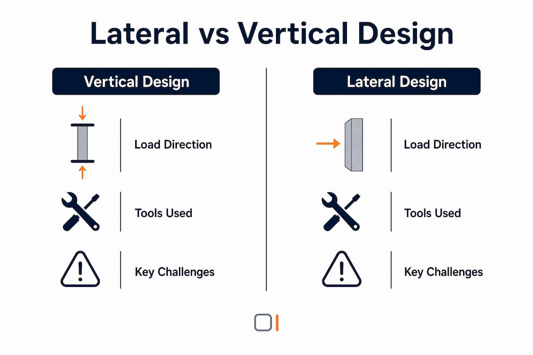
The load path for lateral forces is far less intuitive than for gravity loads. Vertical loads stack neatly from roof to wall to foundation. Lateral loads must be collected at each floor level, distributed across diaphragms, transferred into shear walls, and carried to the foundation through a chain of connections. Every link in that chain must be sized and detailed. That is exactly what lateral design software organizes and calculates.
Core modeling concepts you need to understand
Lateral design software builds a structural model from a specific set of elements. Understanding what those elements represent helps you interpret software output and catch errors before they reach the field.
The primary components modeled in lateral analysis:
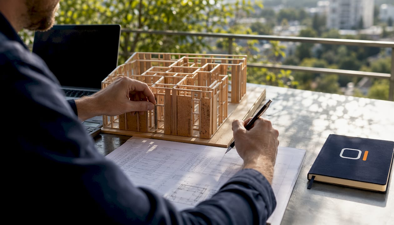
- Diaphragms: Horizontal elements (roofs and floors) that act as deep beams, collecting lateral forces and distributing them to shear walls. Blocked diaphragms carry more shear than unblocked ones.
- Shear walls: Vertical cantilevered panels that resist in-plane lateral forces. Software sizes these by unit shear demand and assigns nailing schedules per AWC SDPWS.
- Drag struts: Horizontal members, typically the double top plate, that collect diaphragm shear and deliver it to shear wall segments.
- Hold-downs: Tension connectors at shear wall ends that resist overturning. Missing or undersized hold-downs are among the most common plan review rejections.
- Transfer straps: Connectors that carry shear across floor levels between diaphragm and wall framing.
"The critical risk in lateral design is incomplete or missing documentation of the load path components, such as drag struts and holdown connections, which software may not fully specify, requiring careful engineer oversight." — Michigan Wood Consortium, Load Path Detailing Lecture
Stiffness assumptions drive how software distributes loads between walls. A rigid diaphragm distributes load in proportion to wall stiffness; a flexible diaphragm distributes load by tributary area. Most light-frame wood buildings use flexible diaphragm assumptions, but the software must be configured correctly or the load distribution will be wrong. Shear walls and diaphragms create the lateral load path together, and the software models both to produce a complete picture of force flow through the structure.
What lateral design software actually does: key features
The feature set across lateral design tools varies by scope, but practitioners consistently rely on a core group of functions. Understanding these helps you evaluate which tool fits your workflow.
Typical features found in lateral design software:
- Wind and seismic load generation from ASCE 7 inputs including site class, exposure category, and occupancy
- Automatic base shear distribution to wall lines based on diaphragm type and wall stiffness
- Shear wall schedule generation with nailing, panel thickness, and boundary element requirements
- Hold-down and strap sizing cross-referenced to hardware catalogs
- Story drift calculation per IBC drift limits
- CAD or BIM import to pull wall geometry directly from drawings, reducing manual input errors
- Code check summaries flagging overstressed elements or missing connections
- PDF report generation formatted for plan review submission
For simple wood-frame or post-frame buildings, simplified hand calculation methods can be more efficient and conservative than complex 3D finite element software. Knowing when to use a focused calculator versus a full structural analysis platform is a judgment call that comes from understanding the underlying method, not just the software output. Engineers who treat lateral design tools as a black box risk missing detailing gaps that the software never flags.
Pro Tip: Before running any lateral analysis, sketch the load path by hand from roof to foundation. If you cannot trace it manually, the software model will not catch the gap either.
How lateral design differs from vertical structural design
Lateral and vertical design share the same building but operate on entirely different principles. Conflating the two is one of the most common sources of structural errors in practice.

Key differences between lateral and vertical design:
| Aspect | Vertical design | Lateral design |
|---|---|---|
| Load direction | Downward (gravity) | Horizontal (wind, seismic) |
| Primary elements | Beams, columns, bearing walls | Shear walls, diaphragms, drag struts |
| Load path logic | Stacked, top to bottom | Collected at each level, transferred laterally |
| Key checks | Bending, shear, deflection | Drift, overturning, unit shear |
| Code provisions | ASCE 7 Chapter 4 (live/dead) | ASCE 7 (wind), ASCE 7 (seismic) |
Vertical loads follow gravity and can be efficiently modeled using Revit Structural Framing tools, but lateral loads require specialized analysis software. They stack predictably from roof to wall to foundation, and conventional framing handles them well without specialized software in most residential cases. Lateral loads require an integrated system of diaphragms and lateral force-resisting elements that must be explicitly designed and connected. The load path is not automatic.
Drift limits add another layer of complexity absent from vertical design. A building can be strong enough to resist lateral forces but still fail if it deflects too much. Story drift checks, typically expressed as a fraction of story height per IBC, require lateral software to calculate accurately. Vertical load software simply does not perform this check.
Pro Tip: Never use a gravity load model to verify lateral performance. The elements, load combinations, and output checks are fundamentally different. Run lateral analysis in a tool built for it.
How ShearWise Pro handles lateral design for wood buildings
ShearWise Pro is an online shear wall calculator built specifically for 1-story and 2-story wood-framed buildings. It targets the most common lateral design scenario in residential and light commercial construction: wood-framed structures where shear walls and diaphragms carry all lateral loads. Rather than requiring a full structural analysis model, ShearWise Pro focuses on the calculations engineers actually need to complete and document.
The platform organizes lateral design around wall lines, which is how engineers naturally think about wood-framed lateral systems. You input wall geometry, openings, and full-height segments; the software calculates unit shear demand, sizes shear wall assemblies, and outputs hold-down forces and transfer strap requirements. Story drift checks are built in, so you do not need a separate calculation to verify displacement compliance.
ShearWise Pro features relevant to lateral design workflows:
- Wall line organization with opening and full-height segment tracking
- Shear wall unit shear calculation per wall line
- Hold-down force output for each shear wall end condition
- Transfer strap sizing between floor levels
- Story drift checks integrated into the analysis
- Clean PDF report generation formatted for plan review and coordination
ShearWise Pro's shear wall software also supports roof diaphragm information input, keeping all lateral design data in one organized workspace. For engineers working on repetitive residential projects, that organization alone reduces coordination errors between the structural drawings and the calculations package.
Pro Tip: Use ShearWise Pro's PDF report as the cover sheet for your lateral calculations package. Reviewers can follow the wall line numbering directly from the report to the plan, cutting back-and-forth during plan check.
Real-world applications of lateral design software in building projects
Lateral design software earns its place on real projects by handling the scenarios where manual methods become impractical or error-prone. Three application types illustrate where the software delivers the most value.
Residential wood-frame design under high wind or seismic demands. A two-story wood-framed house in a high seismic zone requires shear walls on every level, hold-downs at each wall end, and transfer straps at the floor diaphragm. The load path runs from the roof diaphragm through second-floor shear walls, across the floor diaphragm, and into first-floor shear walls before reaching the foundation. Tracking unit shear, hold-down forces, and strap capacities across all wall lines manually is feasible but slow. A focused shear wall calculator organizes this data, runs the checks, and produces a report in a fraction of the time.
Plan revision cycles. Architects frequently move windows and doors after the structural design is underway. Each opening change shifts the available full-height shear wall length, which changes unit shear demand, which changes nailing schedules and hold-down sizes. Lateral design software recalculates the entire wall line instantly when geometry changes. Without it, each revision requires a full manual recalculation, which is where errors tend to enter the design.
Post-frame and light commercial buildings. For straightforward rectangular post-frame buildings, simplified lateral design methods that assume a rigid roof diaphragm and ignore frame-diaphragm stiffness interaction can produce conservative, code-compliant results without complex finite element modeling. Software tools that implement these simplified methods give engineers a fast, auditable calculation path for projects that do not warrant full 3D analysis. The Washington State University research on simplified post-frame lateral design confirms this approach yields conservative unit shear and post moment values for buildings with length-to-width ratios up to 3.
The common thread across all three scenarios is documentation. Plan reviewers and building officials need to see a clear, traceable load path from roof to foundation. Lateral design software, used correctly, produces exactly that record. For engineers working on wood-framed projects, resources like the wood framing lateral systems guide provide additional context on how software fits into the broader lateral system design process.
Try ShearWise Pro for your next lateral design project

ShearWise Pro is built for engineers, architects, designers, and contractors who need organized, code-compliant lateral calculations for 1-story and 2-story wood buildings. The platform covers wall lines, openings, full-height segments, hold-down forces, transfer straps, story drift checks, and PDF report generation in one focused workspace.
Start your lateral design with ShearWise Pro and generate a clean, review-ready calculations package without the overhead of a full structural analysis platform.
Key Takeaways
Lateral design software automates the calculation of horizontal force paths through diaphragms, shear walls, and connections, ensuring code-compliant designs that manual methods cannot efficiently produce at scale.
| Point | Details |
|---|---|
| Core function | Lateral design software calculates base shear, sizes shear walls, and traces the load path from roof to foundation. |
| Load types covered | Wind and seismic loads are the primary inputs, governed by ASCE 7 and IBC provisions. |
| Lateral vs. vertical design | Lateral design requires drift checks, overturning analysis, and integrated diaphragm systems that vertical load software does not address. |
| Software limitations | Hold-down and strap detailing often requires engineer review beyond what software automatically outputs. |
| Wood-frame application | ShearWise Pro organizes wall line calculations, hold-down forces, and PDF reports for 1-story and 2-story wood-framed projects. |