
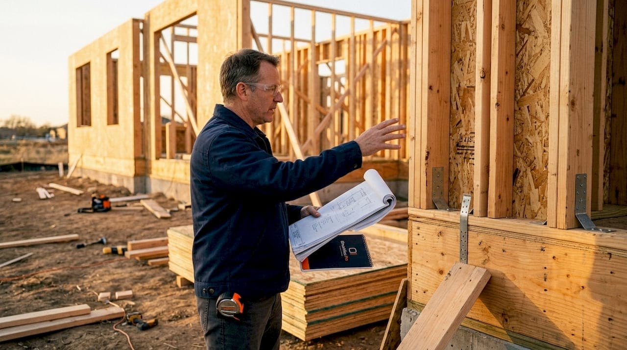
Wood building lateral system components are structural elements designed to resist lateral forces such as wind and seismic loads by creating a continuous load path from roof to foundation. The primary components include diaphragms, shear walls, collectors, hold-downs, and foundation anchorage. Each element plays a defined role in collecting, transferring, and anchoring lateral forces. Per AWC SDPWS and IRC R602.10, these components must work as an integrated system. A break at any connection compromises the entire structure's lateral resistance.
1. Wood building lateral system components: what they are and why they matter
The lateral force-resisting system for light-frame wood buildings consists of diaphragms and vertical shear walls working together as a unit. Wood's flexibility allows energy dissipation under seismic and wind loading, but that same flexibility creates a risk of racking. Racking is the distortion of a wall or frame under lateral load, and it affects both structural integrity and finish systems. Adequate bracing through shear walls and diaphragms is the primary defense against it.
The load path concept is the foundation of all lateral design. Forces enter at the roof, travel through floor diaphragms, transfer into shear walls, pass through collectors and hold-downs, and anchor into the foundation. Failure at any single connection breaks the chain. This is why lateral design is not just about sizing walls. It is about detailing every connection along the path.

2. Diaphragms: collecting and distributing lateral loads
Diaphragms are horizontal structural elements, typically roof and floor assemblies, that collect lateral forces and distribute them to vertical resisting elements. They function like a flat beam spanning between shear walls. The diaphragm's stiffness determines how loads distribute to each wall line below.
Common diaphragm materials include plywood, oriented strand board (OSB), and other wood structural panels. Fastening requirements govern shear capacity. Nail size, spacing at panel edges, and blocking at panel joints all directly affect how much load the diaphragm can transfer. Proper lateral bracing of wood members within the diaphragm also prevents lateral-torsional instability in individual framing members.
AWC SDPWS 2026 provides tabulated and calculated design methods for diaphragms. Blocked diaphragms with closer nail spacing achieve higher unit shear values than unblocked assemblies. Chord members at the diaphragm perimeter carry the tension and compression forces that result from diaphragm bending.
Key diaphragm design considerations:
- Panel type and thickness: OSB and plywood have different published shear values per SDPWS tables.
- Nail schedule: Edge nailing at 2 inches on center versus 6 inches on center can double the diaphragm's capacity.
- Blocking: Blocking at all panel edges is required for higher shear values.
- Chord continuity: Chord splices must transfer tension without interruption.
- Aspect ratio: Diaphragm length-to-width ratios affect whether a flexible or rigid diaphragm assumption applies.
Pro Tip: Specify blocked diaphragms on all projects in Seismic Design Categories C and above. The added framing cost is minor compared to the capacity gain and the reduction in drift.
3. Shear walls: vertical components resisting racking forces
Shear walls are the primary vertical elements in a lateral load resistance system. They receive lateral forces from diaphragms and transfer them down to the foundation. Engineered shear walls use calculated nail patterns, hold-downs, and anchorage to achieve higher unit shear capacities than prescriptive bracing allows.
Two design approaches exist. Prescriptive braced wall panels per IRC R602.10 mandate specific panel sizes, locations, and aggregate lengths for residential buildings. This method requires no engineering calculations but limits design flexibility. Engineered shear walls designed to AWC SDPWS allow higher capacities, irregular layouts, and openings, at the cost of more detailed analysis.
Aspect ratio is a critical variable in shear wall design. Tall, narrow wall segments carry aspect ratio penalties that reduce their effective shear capacity. SDPWS limits the height-to-width ratio for full-capacity segments. Walls exceeding those limits require capacity reduction factors or alternative detailing.
Force Transfer Around Openings (FTAO) is an engineered method that allows wall areas adjacent to windows and doors to contribute shear capacity. Without FTAO, those areas are ignored in the calculation. With FTAO, strap forces above and below openings are explicitly designed, and the full wall length becomes productive.
Key shear wall design elements:
- Sheathing type and nailing: Wood structural panel (WSP) sheathing with specific nail size and spacing per SDPWS tables.
- Hold-downs: Tension anchors at wall ends resist overturning forces.
- Sill plate anchorage: Anchor bolts or plate washers resist sliding at the base.
- Aspect ratio compliance: Verify height-to-width ratios before assigning full capacity.
- FTAO detailing: Strap forces above and below openings must be explicitly sized and specified.
Pro Tip: On projects with many window openings, run an FTAO analysis before defaulting to a longer wall elsewhere. You often find adequate capacity in the existing layout without adding walls.
4. Collectors and hold-downs: maintaining load path continuity
Collectors, also called drag struts, are horizontal elements that gather shear forces from the diaphragm and deliver them to the shear wall below. They bridge the gap between the diaphragm edge and the shear wall end. Without a properly designed collector, forces accumulate with no path into the vertical system.
Hold-down devices resist the overturning tension force at the end of each shear wall. The Simpson Strong-Tie HDUE hold-down series provides known load and deflection performance for standard applications. When loads exceed the capacity of individual hold-down hardware, continuous rod tie-down systems are the preferred solution for multistory buildings.
Wood shrinkage is a problem that continuous rod systems must address directly. Steel rods do not shrink, but wood framing does. Over multiple stories, cumulative shrinkage can reduce hold-down tension to near zero. Take-up devices installed within the rod system compensate for this movement and maintain tension throughout the building's service life.
Key collector and hold-down considerations:
- Collector sizing: Design for both tension and compression; collectors carry reversible forces under wind and seismic loading.
- Hold-down selection: Match hardware to calculated overturning demand, not to a default specification.
- Take-up devices: Required in multistory rod systems to compensate for wood shrinkage.
- Connection continuity: Every splice in a collector must transfer the full design force.
- Transfer straps: Strap connectors at floor levels transfer shear between stories in platform-framed buildings.
Pro Tip: Detail collector splices at the same level of rigor as hold-down connections. Collectors are frequently under-detailed on construction documents, which creates field problems during inspection.
5. Foundation anchorage: transferring lateral loads to the soil
Foundation anchorage is the final link in the lateral load path. Anchor bolts and tension anchors secure shear walls and hold-downs to the concrete foundation, resisting both sliding and overturning. If anchorage fails, the entire lateral system above it becomes ineffective regardless of how well it was designed.
Standard practice uses anchor bolts embedded in concrete to resist sill plate sliding. Plate washers are required at each bolt to engage the full bearing area of the sill plate. For hold-down forces, separate tension anchors or embedded rods connect directly to the hold-down hardware at the wall end.
Seismic and wind design conditions drive anchorage sizing. High seismic zones require closer bolt spacing, larger plate washers, and higher-capacity tension anchors. Inadequate anchorage is one of the most common failure modes observed after major seismic events.
Key anchorage design requirements:
- Anchor bolt spacing: IRC R403.1.6 and SDPWS both specify maximum spacing for sill plate bolts.
- Plate washers: Minimum 3-inch by 3-inch by 0.229-inch plate washers are required in Seismic Design Categories D, E, and F.
- Hold-down anchor rods: Must develop the full tension demand from the shear wall overturning calculation.
- Edge distance and embedment: Concrete edge distance and embedment depth govern anchor capacity per ACI 318 Appendix D.
- Inspection: Anchor bolt placement requires special inspection in higher seismic categories.
6. System interaction and emerging technologies in wood lateral design
Lateral system performance improves significantly when walls are configured in L- and U-shaped plans rather than isolated planar segments. Shake table tests confirm that transverse walls and diaphragm interaction reduce story drift and increase stiffness beyond what planar wall models predict. This means a building with well-configured wall lines performs better than its calculated capacity suggests.
Gravity loads also contribute to lateral resistance. Vertical load on a shear wall increases the overturning resistance and reduces the net tension demand on hold-downs. Designers who account for this effect can reduce hold-down sizes or eliminate them in lightly loaded walls.
Emerging technologies are extending wood construction into taller building types. CLT rocking shear walls with hysteretic dampers represent a validated approach for buildings up to 12 stories. These systems allow controlled rocking motion during seismic events, dissipating energy while limiting structural damage. This is a meaningful shift from traditional platform framing, which relies on distributed ductility in nailed connections.
Validated models for balloon-framed CLT rocking shear walls with dampers show performance suitable for buildings up to 12 stories, offering resilient alternatives to traditional wood framing for taller structures where conventional shear wall systems reach their practical limits.
Continuous rod tie-down systems with shrinkage compensation are now standard practice in multistory wood buildings. Cumulative deflection in stacked hold-downs across multiple floors exceeds the performance of individual hardware. Rod systems with take-up devices solve this problem by maintaining consistent tension at every level.
Key takeaways
The lateral load path in a wood building is only as strong as its weakest connection, making detailing at every node as critical as sizing the walls themselves.
| Point | Details |
|---|---|
| Diaphragms collect and distribute | Roof and floor diaphragms transfer lateral forces to shear walls; nail schedule and blocking control capacity. |
| Shear walls resist racking | Engineered shear walls per SDPWS outperform prescriptive bracing in complex or high-load projects. |
| Collectors and hold-downs connect the path | Drag struts deliver diaphragm forces to walls; hold-downs resist overturning at wall ends. |
| Foundation anchorage closes the loop | Anchor bolts and tension anchors must be sized for both sliding and overturning demands. |
| System effects increase performance | L- and U-shaped wall configurations reduce drift beyond what planar models predict. |
What I've learned about lateral design after years in the field
The most common mistake I see on wood building projects is treating lateral design as a wall-sizing exercise. Engineers calculate shear demand, select a wall type, and move on. The connections get detailed later, often by someone else, often without the same rigor. That is where buildings fail.
Connection continuity is the real work. A shear wall with a perfectly calculated nail schedule accomplishes nothing if the collector above it has an undersized splice or the hold-down anchor rod misses its embedment depth. I have reviewed projects where the wall design was textbook correct and the anchorage was completely inadequate. The wall would have rocked off the foundation before the sheathing nails yielded.
Shrinkage in multistory buildings is the second issue that gets underestimated. Designers specify continuous rod systems and then forget to specify take-up devices. The rods stay the same length. The wood shrinks. After two or three stories, the hold-down tension is gone. This is not a theoretical concern. It is a documented failure mode.
My recommendation for complex projects is to move away from prescriptive bracing early in the design process. Prescriptive methods work for simple residential layouts, but they limit your options and often produce more wall than you need in the wrong locations. Engineered shear wall design gives you control over placement, capacity, and detailing. That control is worth the additional calculation time.
Early coordination between the structural engineer and the contractor matters more than most designers admit. Anchor bolt placement, hold-down installation, and blocking requirements all need to be understood in the field before concrete is poured and framing begins. A pre-construction meeting focused on the lateral system saves far more time than it costs.
— Evalin
ShearWise Pro: shear wall design built for the lateral load path
Designing wood lateral systems requires tracking wall lines, segments, openings, hold-down forces, and story drift across every level of a building. ShearWise Pro organizes all of that in one place for 1-story and 2-story wood-framed projects.

The platform calculates shear wall capacity, hold-down forces, transfer strap demands, and story drift checks aligned with current SDPWS standards. It generates clean PDF reports ready for plan review and coordination. Engineers and architects use ShearWise Pro to move from load input to complete design reports without rebuilding calculations from scratch on each project. If you work on wood-framed buildings and need organized, code-aligned shear wall output, try ShearWise Pro and see how it fits your workflow.
FAQ
What are the main components of a wood building lateral system?
The main components are diaphragms, shear walls, collectors, hold-downs, and foundation anchorage. Each element transfers lateral forces along a continuous load path from the roof to the foundation.
What is a lateral bracing system in wood construction?
A lateral bracing system is the set of structural elements that resist wind and seismic forces in a wood building. It includes horizontal diaphragms and vertical shear walls connected by collectors and anchored to the foundation.
How do shear walls differ from prescriptive braced wall panels?
Prescriptive braced wall panels per IRC R602.10 use code-specified sizes and locations without engineering calculations. Engineered shear walls per SDPWS use calculated nail patterns and hold-downs to achieve higher capacities and accommodate irregular layouts.
Why are hold-downs critical in wood shear wall design?
Hold-downs resist the overturning tension force at the end of each shear wall. Without them, lateral loads cause the wall to lift off the foundation, eliminating its shear capacity entirely.
What is Force Transfer Around Openings (FTAO)?
FTAO is an engineered method that allows wall areas adjacent to windows and doors to contribute to shear capacity. It requires explicit design of strap forces above and below each opening per AWC SDPWS provisions.