

Lateral load distribution is defined as the structural process of transferring horizontal forces through a building's diaphragm to its vertical lateral resisting elements, including shear walls, moment frames, and braced frames. Lateral loads include wind, seismic activity, and soil or water pressure, all of which act horizontally and challenge building stability in ways that gravity loads do not. ASCE 7-16 governs how engineers classify diaphragms and apply load combinations to account for these forces. Understanding what is lateral load distribution is the foundation of every compliant structural design for wood, concrete, and steel buildings.
What is lateral load distribution in structural design?
Lateral load distribution is the method by which horizontal forces move from the point of application through the diaphragm and into the vertical lateral force resisting system (LFRS). Floor diaphragms act as horizontal beams that collect lateral forces and transfer them to shear walls, braced frames, or moment frames. This load path must be continuous and uninterrupted from the roof to the foundation.
The distinction between gravity loads and lateral loads is fundamental. Gravity loads act vertically downward and are resisted by columns, beams, and bearing walls. Lateral loads act horizontally and require a separate resisting system designed specifically for that direction. ASCE 7 load combinations include load factors and interaction terms that account for simultaneous vertical and lateral forces, which means you cannot design for one without considering the other.
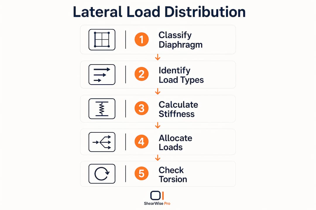
The vertical elements of the LFRS do not share lateral loads equally. The proportion each element carries depends on diaphragm classification and the relative stiffness of each vertical element. Getting this allocation right is the core challenge of lateral load analysis.

How does diaphragm rigidity affect lateral force distribution?
Diaphragm classification controls which distribution method you apply. ASCE 7-16 defines three categories: rigid, flexible, and semi-rigid. Each category produces a different load path and a different set of forces on the vertical elements.
| Diaphragm type | Classification criterion | Distribution method |
|---|---|---|
| Flexible | In-plane deformation exceeds twice the average story drift | Tributary area method |
| Rigid | In-plane deformation is small relative to story drift | Relative stiffness method |
| Semi-rigid | Behavior falls between rigid and flexible | Finite element analysis |
A flexible diaphragm distributes lateral loads based on the tributary mass or area each vertical element serves. This is the simpler calculation, and it is appropriate for light wood-frame buildings with plywood sheathing where the diaphragm deflects significantly. A rigid diaphragm, by contrast, distributes loads based on the relative stiffness of the vertical elements below it. Stiffer walls attract more load regardless of their tributary area.
Semi-rigid diaphragms present the most complex case. Many modern buildings have diaphragms classified as semi-rigid due to large openings and irregular plan geometry. Finite element analysis is required to accurately model their behavior. Skipping this step and assuming full rigidity can produce dangerously unconservative results for individual shear walls.
Pro Tip: Classify the diaphragm before selecting a distribution method. Misclassification is one of the most common sources of error in lateral load analysis, and it propagates through every downstream calculation.
For a deeper look at how diaphragm chords interact with the distribution process, the mechanics of chord forces and collector elements are directly tied to which diaphragm classification applies.
What determines how much lateral load each vertical element carries?
In rigid diaphragm systems, relative stiffness controls how lateral loads are distributed among vertical resisting elements. A stiffer shear wall attracts a larger share of the total lateral force, independent of its ultimate strength capacity. This is a linear elastic behavior, and it has direct consequences for design.
| Vertical element type | Relative stiffness | Typical load share in rigid diaphragm |
|---|---|---|
| Concrete shear wall | High | Largest share |
| Steel braced frame | Moderate to high | Significant share |
| Moment frame | Low to moderate | Smaller share |
| Light wood shear wall | Low | Smallest share |
Members with higher stiffness attract more load regardless of their ultimate strength. This means a wall that is strong but flexible will carry less load than a wall that is stiff but weaker. Engineers who design only for strength without checking stiffness compatibility risk overloading the stiffer elements in the system.
Differential stiffness between elements also creates torsional effects. When the center of rigidity does not align with the center of mass, the building rotates under lateral load. This eccentric loading adds forces to the outermost vertical elements beyond what a simple tributary or stiffness calculation would predict. ASCE 7-16 requires accidental torsion to be included in the analysis even when the centers appear to align.
Selecting the LFRS requires balancing stiffness and ductility. A very stiff system limits sway under wind loads but may behave in a brittle manner under seismic forces. A more ductile system absorbs energy through controlled deformation. The right answer depends on the seismic design category, the building's occupancy, and the code-prescribed response modification factor.
Pro Tip: Check the center of rigidity against the center of mass early in the design process. Correcting torsional imbalance at the schematic stage costs far less than redesigning wall lines after structural drawings are complete.
Common errors in lateral load design
Lateral load design contains several failure modes that appear regularly in practice. Understanding them prevents costly errors and code violations.
-
Assuming rigid diaphragm behavior universally. Wood-frame buildings with plywood diaphragms are typically flexible. Applying rigid diaphragm distribution to a flexible system overloads interior walls and underloads perimeter walls. Assuming rigid diaphragms in buildings with large openings can dangerously underestimate forces on individual shear walls.
-
Ignoring out-of-plane forces. In-plane forces test shear walls for sliding and overturning, while out-of-plane forces test bending and connections. Both must be designed separately. Failing to address out-of-plane loading leads to connection failures at wall-to-diaphragm interfaces.
-
Neglecting the P-delta effect. P-delta effects create secondary moments that increase lateral displacement and reduce stability. Gravity loads shift laterally as the structure sways, creating a feedback loop that amplifies drift. Taller or more flexible structures are especially vulnerable, and the effect must be included in the analysis to avoid geometric instability.
-
Designing for one direction only. Lateral loads act in any horizontal direction. Wind and seismic forces must be applied along both principal axes of the building, and the critical combination governs design. Omitting one direction is a code violation under ASCE 7-16.
-
Overlooking torsional amplification. Buildings in higher seismic design categories require torsional amplification factors when the maximum story drift exceeds 1.2 times the average drift. Skipping this check underestimates forces on the most heavily loaded walls.
Many architects and contractors overlook lateral loading entirely, treating it as a secondary concern after gravity design is complete. Lateral load analysis must run parallel to gravity design, not after it, because wall placement decisions made early in the design process directly control the load path.
Practical application of lateral load distribution in building design
Lateral load distribution principles apply differently depending on the structural material and system. Reinforced concrete buildings typically use rigid diaphragms with concrete shear walls or moment frames as the vertical LFRS. Timber frame buildings require a different approach because the timber frame itself carries gravity loads but is not inherently designed to resist lateral forces.
Engineered wall systems like SIPs and framed shear walls are increasingly used in timber construction to provide lateral resistance. Modern timber design separates the gravity load function from the lateral load function. The timber frame carries vertical loads; the shear walls or SIP panels carry horizontal forces. This separation makes the load path explicit and easier to verify during plan review.
Best practices for applying lateral load distribution in design include:
- Establish a complete, continuous load path from the roof diaphragm to the foundation before finalizing wall layouts.
- Classify the diaphragm per ASCE 7-16 thresholds before selecting a distribution method.
- Check the center of rigidity and center of mass for torsional offset at each story.
- Design shear walls for both in-plane shear and overturning, and verify hold-down forces at each end.
- Apply lateral loads along both principal axes and use the governing combination for each element.
- Include P-delta effects in the analysis for buildings with significant lateral drift or flexible systems.
- Verify that the load path transfers continuously through collectors, chords, and connections to the foundation.
For wood-framed residential projects, wall line analysis is the practical method for distributing lateral forces to individual shear wall segments. Each wall line receives a share of the total story shear based on its tributary area or relative stiffness, and each full-height segment within that line is then sized for its portion of the wall line force. ShearWise Pro organizes this process by wall line, tracking full-height segments, hold-down forces, and transfer straps within a single project file.
For engineers working on wood framing lateral systems, the 2026 code cycle reinforces the requirement to document the complete load path in the structural calculations, including diaphragm classification, collector design, and foundation anchorage.
Key takeaways
Lateral load distribution is the process of transferring horizontal forces through a classified diaphragm to vertical resisting elements, with relative stiffness and diaphragm rigidity controlling the share each element carries.
| Point | Details |
|---|---|
| Diaphragm classification first | Classify as rigid, flexible, or semi-rigid before selecting a distribution method per ASCE 7-16. |
| Stiffness drives load share | In rigid diaphragm systems, stiffer vertical elements attract larger portions of the lateral force. |
| Design both directions | Apply lateral loads along both principal axes and design separately for in-plane and out-of-plane forces. |
| P-delta must be included | Secondary moments from P-delta effects increase drift and must be accounted for in flexible or tall structures. |
| Load path must be continuous | Forces must transfer without interruption from the roof diaphragm through collectors and shear walls to the foundation. |
Why lateral load distribution is the most underestimated calculation in structural design
After years of reviewing structural calculations for wood-framed buildings, the pattern I see most often is not a math error. It is a classification error made at the very start of the analysis. Engineers apply rigid diaphragm distribution to a light wood-frame building, then size every shear wall based on relative stiffness, when the diaphragm is clearly flexible by ASCE 7-16 criteria. The numbers look internally consistent, but the underlying assumption is wrong, and the wall forces are wrong as a result.
The second pattern I see is treating lateral load design as a checklist item rather than a load path problem. A shear wall that is correctly sized for shear but missing a hold-down at the end is not a compliant design. The load path breaks at the connection, and the wall cannot perform its function. This is why I always review the full load path from diaphragm to foundation before signing off on any calculation set.
The field is moving toward better tools and more explicit modeling, which I think is the right direction. Semi-rigid diaphragm modeling used to require specialized finite element software. Today, more accessible platforms make it practical for smaller projects. The engineers who invest time in understanding diaphragm behavior and stiffness distribution will produce better designs and fewer RFIs during construction.
Balancing stiffness and ductility is the judgment call that separates adequate designs from good ones. A structure that is stiff enough to limit drift under wind but ductile enough to absorb seismic energy without brittle failure requires deliberate system selection, not just code minimums. That judgment comes from understanding the principles, not just running the numbers.
— Evalin
ShearWise Pro for lateral load and shear wall design
Engineers and architects working on 1-story and 2-story wood-framed buildings need a calculation platform that keeps the lateral load path organized from wall line to foundation.

ShearWise Pro organizes shear wall calculations by wall line, tracks full-height segments, hold-down forces, transfer straps, and story drift checks in a single project file. The platform generates clean PDF reports formatted for plan review and coordination. For engineers who need to document the complete lateral load path efficiently and accurately, ShearWise Pro reduces calculation time and keeps every design decision traceable. Sign up to try ShearWise Pro and run your first project today.
FAQ
What is lateral load distribution?
Lateral load distribution is the structural process of transferring horizontal forces through a building's diaphragm to its vertical resisting elements, including shear walls, braced frames, and moment frames. The distribution method depends on whether the diaphragm is classified as rigid, flexible, or semi-rigid per ASCE 7-16.
What is the difference between gravity and lateral loads?
Gravity loads act vertically downward and are resisted by columns, beams, and bearing walls. Lateral loads act horizontally from wind, seismic activity, or soil pressure and require a separate lateral force resisting system designed specifically for horizontal forces.
How does diaphragm rigidity affect load distribution?
A rigid diaphragm distributes lateral loads based on the relative stiffness of vertical elements below it. A flexible diaphragm distributes loads based on tributary area. Semi-rigid diaphragms require finite element analysis to model accurately.
What are the most common errors in lateral load design?
The most common errors include misclassifying the diaphragm, ignoring out-of-plane forces, omitting P-delta effects, designing for only one lateral direction, and failing to verify a continuous load path from the diaphragm to the foundation.
What is a lateral load addition in an existing building?
A lateral load addition refers to a structural modification or new element added to an existing building to increase its lateral force resistance, such as adding shear walls, braced frames, or a new diaphragm connection. These additions require a full lateral load analysis to verify the updated load path and element capacity.