
Wall line analysis is the process of identifying and evaluating braced wall lines, which are imaginary centerlines representing the lateral resistance pathways in wood-framed construction. Architects and engineers perform this analysis to verify that shear wall panels are correctly distributed, that spacing between lines meets code limits, and that cumulative bracing length satisfies the International Residential Code (IRC) and the Special Design Provisions for Wind and Seismic (SDPWS). Getting this right is not optional. Under 2026 building codes, non-compliant wall line layouts trigger redesign, permit delays, and potential structural deficiency.
What is a wall line analysis in wood-framed construction?
A braced wall line is defined as an imaginary straight line representing the centerline of lateral resistance in a wood-framed building. The line does not have to coincide exactly with a physical wall. Actual sheathed panels must fall within 4 feet of that centerline to satisfy code. This "floating" allowance gives architects flexibility when architectural features push walls slightly off the ideal grid.
Wall line analysis, as the industry commonly calls it, maps these conceptual lines across a floor plan, assigns shear wall panels to each line, and checks that the combined system resists wind and seismic loads. The formal industry term is braced wall line analysis, though both phrases appear in practice. Using the correct term in permit documents avoids confusion with reviewers who expect IRC language.

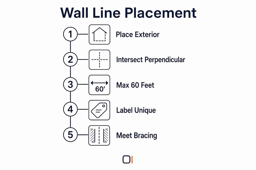
Braced wall lines must be placed along exterior walls, with intersections at perpendicular ends. Interior braced wall lines are also permitted when the layout requires additional lateral resistance. Proper establishment of these lines distributes shear forces evenly and prevents torsional effects that can compromise building stability.
How are braced wall lines placed and spaced on a layout plan?
Code placement rules follow a clear hierarchy. Braced wall lines run parallel to one another, and the distance between parallel lines cannot exceed 60 feet. Exceeding that limit triggers additional design requirements or forces a redesign of the wall line layout plan. Within each line, individual braced panels cannot be spaced more than 20 feet apart.
The table below summarizes the key placement rules architects and engineers verify during a wall line layout review.
| Requirement | Code Limit | Consequence of Violation |
|---|---|---|
| Max spacing between parallel braced wall lines | 60 feet | Additional design requirements triggered |
| Max spacing between panels within a line | 20 feet | Uneven load distribution, non-compliance |
| Allowable float from centerline to actual panel | 4 feet | Panel falls outside the braced wall line |
| Panel cumulative length | Varies by height and roof slope | Insufficient lateral resistance |
Braced wall panels must cumulatively meet or exceed code-specified bracing lengths per wall line, factoring in building height, roof height, and the number of braced lines. A two-story building with a steep roof slope requires more cumulative bracing than a single-story flat-roof structure. Engineers who skip this cumulative check often discover deficiencies late in the permit review process.
Pro Tip: Label each braced wall line on the floor plan with a unique identifier (A, B, C for one direction; 1, 2, 3 for the perpendicular direction). This makes cross-referencing calculations and plan sheets far faster during permit review.
How do you analyze load distribution among multiple shear wall segments?
Engineers use two primary methods to distribute lateral shear forces among multiple shear wall segments along a single braced wall line. Selecting the wrong method produces inaccurate capacity predictions and unsafe design margins.
The equal deflection method assumes that all connected shear walls along the line deflect equally under load. Load is then distributed to each segment based on its relative stiffness. This method applies when the diaphragm and framing provide enough continuity to force equal deflection across segments.
The simplified shear distribution method distributes load proportionally to segment length or strength when framing continuity is less certain. It is more conservative and easier to apply in the field, but it can underestimate capacity when stiffer segments are present. The table below contrasts the two approaches.
| Criterion | Equal deflection method | Simplified distribution method |
|---|---|---|
| Basis of distribution | Relative stiffness of each segment | Segment length or rated strength |
| Framing continuity required | Yes, high continuity assumed | No, works with discontinuous framing |
| Accuracy | Higher when continuity exists | Conservative, may underestimate capacity |
| Complexity | More calculation steps | Simpler, faster to apply |
| Best use case | Rigid diaphragm, connected segments | Flexible diaphragm, isolated segments |
Many practitioners neglect relative stiffness differences between segments, leading to inaccurate capacity evaluations. A common error is treating two adjacent shear walls as equal contributors when one is twice as stiff as the other. The stiffer wall attracts more load, and ignoring that difference can push it past its design capacity.
Pro Tip: When using the equal deflection method, calculate the deflection of each segment individually before combining them. If deflections differ by more than 20%, reconsider whether the equal deflection assumption is valid for that wall line.
For a detailed walkthrough of full-height segment design under 2026 code provisions, the ShearWise Pro blog covers the calculation steps with code references.
Why does wall line terminology cause confusion on job sites?
The acronym "WL" creates a specific and recurring problem on construction documents. In architectural drawings, "WL" commonly stands for "wall lining," which refers to interior finish materials such as gypsum board or paneling. It does not refer to a structural braced wall line. When a contractor reads "WL" on a structural plan and interprets it as a finish material note, the result is a missed shear wall installation.
This terminology gap matters because braced wall lines are conceptual, not physical. The line itself is invisible on a built structure. Only the sheathed panels, hold-downs, and straps are physical. Clear differentiation between wall lining and wall line analysis terminology is vital to avoid miscommunication that negatively impacts construction outcomes.
Architects and engineers can address this with three practices:
- Spell out "braced wall line" in full on structural plans rather than using the abbreviation "WL."
- Add a legend to the structural plan set that defines all abbreviations used in lateral design drawings.
- Coordinate with the contractor during the pre-construction meeting to confirm that braced wall line locations are understood as structural, not architectural, elements.
These steps take minutes to implement and prevent costly field corrections. Miscommunication between design and construction teams on lateral systems is one of the most common sources of structural non-compliance during inspections.
How do you apply wall line analysis to optimize structural design?
Wall line analysis is most effective when it starts at the schematic design phase, not after the floor plan is locked. Early placement of braced wall lines shapes window and door locations, corridor widths, and open-plan layouts. Waiting until construction documents to run the analysis forces expensive plan revisions.
The following steps describe a practical wall line analysis workflow for 1-story and 2-story wood-framed buildings.
- Identify the building's lateral load demands. Calculate wind and seismic forces using the site's design parameters and the applicable 2026 code edition.
- Establish braced wall line locations. Place lines along exterior walls first, then add interior lines if spacing exceeds 60 feet in either direction.
- Assign shear wall panels to each line. Verify that each panel falls within 4 feet of the line's centerline and that panels are spaced no more than 20 feet apart.
- Calculate cumulative bracing length. Sum the lengths of all panels on each line and compare against the code-required minimum, adjusted for building height and roof slope.
- Select a load distribution method. Apply the equal deflection method or the simplified distribution method based on framing continuity and diaphragm type.
- Check wall line spacing. Confirm that no two parallel braced wall lines are more than 60 feet apart.
- Verify hold-down and strap requirements. Each full-height segment needs hold-down forces and transfer straps sized for the actual load it carries.
- Generate a coordinated report. Document wall line IDs, panel locations, capacities, and code references in a format the plan reviewer can follow.
Wood framing lateral systems require this level of documentation to pass permit review in most jurisdictions. ShearWise Pro organizes wall lines, segments, openings, hold-down forces, and story drift checks into a single PDF report, which reduces back-and-forth with plan reviewers.
Verifying spacing between braced wall lines does not exceed code limits prevents structural deficiency caused by uneven lateral load distribution. Architects who treat this check as a final step rather than a design driver often find that their open-floor-plan layouts require significant structural additions to comply.
Wall line analysis deserves more attention than it gets
Most structural failures in light wood-frame buildings trace back to lateral system deficiencies, not gravity load problems. I have reviewed dozens of permit-rejected plans where the gravity framing was perfectly sized but the braced wall lines were either missing, spaced too far apart, or assigned panels that did not add up to the required cumulative length. The fix is always the same: go back to the floor plan and redesign the lateral system from scratch.
The conceptual nature of braced wall lines is what trips up less experienced designers. A line that "floats" up to 4 feet from actual panels sounds flexible, but that flexibility has hard limits. When a designer moves a sheathed wall 5 feet from the centerline to accommodate a window, the panel no longer counts toward that line's capacity. The math changes, and the design fails.
My strongest advice is to run the wall line analysis in parallel with the architectural floor plan, not after it. The two are not independent. A floor plan that ignores lateral system requirements will always produce a structural design that fights the architecture. When you integrate braced wall line placement into early design decisions, the structural and architectural drawings align naturally, and permit review goes faster.
Tools like ShearWise Pro make this integration practical. Organizing wall lines, segments, and hold-down forces in one place means you catch spacing violations and cumulative length deficiencies before they reach the plan reviewer's desk.
— Evalin
ShearWise Pro: wall line analysis built into every calculation
ShearWise Pro is a focused shear wall calculator and report platform built for engineers, architects, designers, and contractors working on 1-story and 2-story wood-framed projects.
The platform organizes wall lines, full-height segments, openings, hold-down forces, transfer straps, and story drift checks in one place. Every calculation ties directly to a clean PDF report formatted for permit submission. You can review sample ShearWise reports to see how wall line IDs, panel capacities, and code references appear in a finished document. When you are ready to run your own analysis, sign up to try ShearWise Pro and work through a complete wall line calculation on your next project.
Key takeaways
Wall line analysis is the structured process of placing, spacing, and verifying braced wall lines so that shear wall panels collectively resist lateral loads within code limits.
| Point | Details |
|---|---|
| Braced wall lines are conceptual | Actual panels must fall within 4 feet of the centerline to count toward capacity. |
| Spacing limits are hard code limits | No two parallel braced wall lines may be more than 60 feet apart under the IRC. |
| Method selection affects accuracy | The equal deflection method requires framing continuity; the simplified method is more conservative. |
| Terminology errors cause field mistakes | "WL" means wall lining in architectural drawings, not a structural braced wall line. |
| Early analysis saves redesign time | Running wall line analysis during schematic design prevents costly plan revisions later. |
FAQ
What is a braced wall line?
A braced wall line is an imaginary straight line representing the centerline of lateral resistance in a wood-framed building. Sheathed panels must be located within 4 feet of this line to satisfy code requirements.
What is wall line distribution?
Wall line distribution refers to how lateral shear forces are shared among multiple shear wall segments along a single braced wall line. Engineers use either the equal deflection method or the simplified shear distribution method to calculate each segment's share of the total load.
How far apart can braced wall lines be?
Braced wall lines must be spaced so that no two parallel lines are more than 60 feet apart. Individual panels within a line cannot be spaced more than 20 feet apart.
What does "WL" mean on a structural drawing?
In architectural drawings, "WL" typically stands for wall lining, which is an interior finish material. On structural drawings, the full term "braced wall line" should be spelled out to avoid confusion with finish material notes.
How does ShearWise Pro support wall line analysis?
ShearWise Pro organizes wall lines, segments, hold-down forces, and story drift checks into a single calculation workflow for 1-story and 2-story wood-framed buildings. The platform generates PDF reports formatted for permit review, reducing coordination time between engineers and plan reviewers.