

Wood frame building lateral analysis is the process of evaluating and designing the structural elements that resist wind and seismic forces in wood-framed construction. Done correctly, it produces a continuous load path from roof to foundation, with every shear wall, diaphragm, and connection carrying its share of the applied force. Done poorly, it leaves gaps that earthquakes or wind events will find.
The core system relies on three elements working together:
- Shear walls resist in-plane lateral forces and transfer them to the floor or foundation below
- Diaphragms (floor and roof assemblies) collect and distribute lateral loads to the shear walls
- Hold-downs and connectors anchor the system, preventing uplift and sliding at critical boundaries
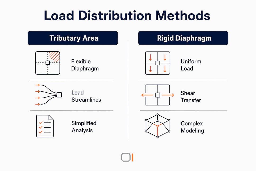
Load distribution follows one of two primary methods: the tributary area method (flexible diaphragm assumption) or the rigid diaphragm method based on relative wall stiffness. Code selection between them is governed by diaphragm stiffness ratio relative to the supporting shear walls. ASCE 7-16 and the National Design Specification (NDS) for Wood Construction set the governing standards for both component design and system-level performance. Tools like ShearWise Pro organize these calculations into a structured workflow, reducing coordination errors and accelerating plan review.
What makes up the lateral force resisting system in wood frame buildings?
The lateral force resisting system (LFRS) in light-frame construction is more than just shear walls. Every component has a defined role, and LFRS complexity demands attention to both component capacity and connection detail.
- Shear walls: Framed walls sheathed with wood structural panels (WSP), structural fiberboard, or gypsum wallboard. The sheathing-to-framing nailing schedule governs unit shear capacity. Aspect ratio limits apply: WSP walls above 3.5:1 height-to-width are not permitted, and capacity reductions apply above 2:1. Segmented and perforated design methods each handle openings differently.
- Diaphragms: Roof and floor assemblies act as horizontal beams, spanning between shear wall lines. Boundary elements (double top plates, rim joists, beams) form chords that carry tension and compression. Collectors, also called drag struts, transfer diaphragm forces into shear walls that do not run the full diaphragm width. A full diaphragm chord design check covers aspect ratio, shear, deflection, chord forces, and collector forces.
- Hold-downs and anchor bolts: Hold-downs resist the overturning tension at shear wall ends. Anchor bolts transfer base shear from the wall bottom plate to the foundation. Both must be sized for the full calculated demand, including any load path amplification from upper stories.
- Transfer straps and blocking: Where shear walls are offset between floors, transfer straps and blocking carry the force across the diaphragm to the wall below. ASCE 7 §12.10.1.1 specifically addresses transfer force design when wall stiffness changes significantly between stories.
- Nonstructural partitions: Research published in the Journal of Structural Engineering found that partition walls accounted for a significant portion of overall lateral resistance in low-rise wood frame buildings. Prescriptive code tables were historically calibrated assuming partitions were present, so removing them from a design without compensating shear walls can leave a building under-designed.
A thorough understanding of these lateral system components is the foundation for every calculation that follows.
How do engineers distribute lateral loads to shear walls?
Selecting the right distribution method is one of the most consequential decisions in structural analysis of wood frame buildings. The choice depends on diaphragm stiffness relative to the shear walls it supports.
- Tributary area method (flexible diaphragm): Each shear wall line carries the lateral load from its tributary area, with no force sharing between parallel walls. ASCE 7-16 Section 12.3.1.1 permits light-frame wood diaphragms to be classified as flexible in most standard configurations. The method is simple and widely used, but it can underestimate loads on stiffer wall segments and miss the resistance of shorter walls in irregular plans.
- Rigid diaphragm method: Load distributes to shear walls in proportion to their relative stiffness. This approach is more accurate for buildings where the diaphragm is significantly stiffer than the walls. It also captures torsional effects when the center of mass and center of rigidity are offset, adding a torsional shear component to each wall line.
- Semi-rigid diaphragm behavior: Research using a multiple spring model found that semi-rigid diaphragm forces transferred to shear walls can exceed those predicted by either the flexible or rigid assumption. Using only the envelope of the two extreme cases is not always conservative. Engineers working on irregular or long-span buildings should recognize this gap.
- Code guidance on method selection: The governing building code directs method selection based on calculated stiffness ratios. For seismic design, the diaphragm classification must be consistent with the analysis method used for the vertical elements. Wind design typically uses tributary areas tied to exterior wall surfaces, while seismic design uses plan-based tributary areas.
A detailed breakdown of each approach is available in the lateral load distribution guide for engineers working through specific project configurations.
Engineering workflow for wood frame lateral system design
A reliable lateral design follows a defined sequence. Skipping steps or reordering them creates coordination problems that surface during plan check or, worse, during construction.
- Define the architectural layout. Wall locations, floor plan geometry, and opening sizes all constrain where shear walls can go. Layouts with long unbroken wall lines are straightforward; irregular plans with large openings or re-entrant corners require more analysis effort from the start.
- Calculate lateral loads. Determine wind loads per ASCE 7-16 Chapter 27 or 28 (depending on building type) and seismic loads per ASCE 7-16 Chapter 12. For seismic, calculate the base shear V using the Equivalent Lateral Force procedure, then distribute story forces Fx to each level.
- Distribute loads to the LFRS. Apply the tributary area or rigid diaphragm method to assign shear demand to each wall line. For multi-story buildings, accumulate forces from upper stories into lower wall lines.
- Design shear wall assemblies. Select sheathing type, panel thickness, and nailing schedule from AWC SDPWS tables to meet the required unit shear. Check aspect ratio limits. For seismic, use the ASD seismic capacity (nominal divided by 2.8); for wind, divide by 2.0.
- Design hold-downs and anchorage. Calculate overturning demand at each shear wall end. Size hold-down hardware and anchor bolts accordingly. Account for cumulative uplift in multi-story buildings, where hold-down forces from upper stories stack onto lower-story demands.
- Detail load path continuity. Trace the shear wall load path from roof diaphragm through each floor to the foundation. Identify collectors, transfer straps, and blocking requirements at every level transition.
- Check story drift. Calculate shear wall deflection using the SDPWS four-term equation. Confirm drift stays within ASCE 7-16 limits. For seismic, run deflection checks at strength-level loads (multiply ASD loads by 1.4).
- Evaluate chords and collectors. Check tension and compression in double top plates and rim joists acting as diaphragm chords. Verify collector (drag strut) capacity at each shear wall end.
The wall line analysis guide covers this sequence in detail, with worked examples for both regular and irregular plan configurations. For multi-story buildings, load path continuity between floors is the most common source of design errors. ASCE 7-16 §12.10.1.1 requires explicit transfer force design wherever shear walls are discontinued or offset between stories.
Pro Tip: Design provisions often focus on individual elements. Integrating a whole-building system view that accounts for redundancy and nonstructural contributions produces more accurate and reliable lateral designs.
How does finite element analysis improve wood frame lateral modeling?
Finite element analysis (FEA) gives engineers a way to model the full lateral response of a wood frame building, capturing interactions that simplified hand methods cannot represent.
- What FEA models: Wall stiffness, diaphragm flexibility, connection behavior, and the interaction between structural and nonstructural elements. Shear walls are typically modeled as macroelements; diaphragms as plate or beam elements with calibrated stiffness.
- Validated accuracy: FEA models validated against physical tests accurately capture diaphragm and shear wall stiffness interactions, improving load distribution predictions over simplified methods.
- Semi-rigid diaphragm capture: FEA can represent the intermediate stiffness range where neither the flexible nor rigid assumption applies. This is where the largest discrepancies between simplified and actual behavior occur.
- Transfer force tracking: In multi-story buildings with offset or discontinued shear walls, FEA tracks transfer forces through the diaphragm with precision that hand calculations cannot match for complex geometries.
- Limitations: FEA requires calibrated input parameters, significant modeling time, and expertise in interpreting results. Computational cost scales with building complexity. For most 1- and 2-story residential projects, simplified methods with good engineering judgment are sufficient. FEA is most justified for irregular multi-story buildings, research validation, or high-seismic-zone projects where simplified assumptions carry meaningful risk.
ShearWise Pro organizes your lateral design workflow
ShearWise Pro is a focused shear wall calculator and report platform built for engineers, architects, designers, and contractors working on 1-story and 2-story wood-framed projects. It handles the calculations that take the most time in a typical lateral design workflow.
- Wall line management: Organize shear walls by wall line, with separate entries for each full-height segment, opening, and boundary condition. The platform tracks wall line totals and flags segments that exceed aspect ratio limits.
- Hold-down and transfer strap design: Calculate hold-down forces and transfer strap demands directly within the project, with outputs tied to the specific wall segments generating the demand.
- Story drift checks: Run deflection calculations per SDPWS equations and confirm compliance with ASCE 7 drift limits, with results organized by wall line for easy review.
- PDF report generation: Generate clean, organized design reports for plan review coordination. Reports include wall line summaries, segment details, hold-down schedules, and drift check results.
- Code integration: ShearWise Pro aligns with ASCE 7 and NDS requirements, so the calculations you run match the standards your plan checker expects.
Evalin contributes content and engineering expertise to ShearWise Pro's educational resources, supporting engineers who want deeper context alongside the calculation workflow.
Common failure modes in wood frame lateral systems and how to mitigate them
Most lateral system failures trace back to one of a small set of recurring problems. Knowing where they occur helps you design against them from the start.
Inadequate hold-down capacity is the most common single-element failure. Overturning forces at shear wall ends are often underestimated, particularly in multi-story buildings where upper-story demands accumulate. Size hold-downs for the full calculated tension demand, including any shrinkage-related slack in the hardware over time.
Broken load paths occur when a force has no continuous route from the diaphragm to the foundation. Common breaks include missing collectors at shear wall ends, unblocked diaphragm edges, and floor-to-wall connections that were detailed for gravity only. Every lateral force needs a complete path; trace it explicitly on the drawings.
Torsional irregularity develops when shear walls are concentrated on one side of a building, shifting the center of rigidity away from the center of mass. The resulting torsional demand adds to direct shear in the walls farthest from the center of rigidity. Distribute wall lines as symmetrically as the architectural layout allows, and check torsional amplification per ASCE 7 when irregularities exist.
Diaphragm openings without detailing create stress concentrations around stairwells, skylights, and mechanical chases. Forces must be redirected around the opening using chord members and drag struts. Skipping this detailing leaves the diaphragm unable to transfer forces across the gap.
Overreliance on partition walls cuts both ways. Partitions add lateral resistance that prescriptive designs historically assumed was present. Removing partitions for open-plan layouts without adding engineered shear walls reduces system capacity below what the prescriptive tables assumed.
Step-by-step lateral load calculation for a typical wood frame building
The following example walks through a simplified seismic lateral load calculation for a single-story wood frame building. Assume a rectangular plan, 36 ft long by 24 ft wide, with a seismic base shear V = 9 kips distributed to the roof diaphragm.
Step 1: Distribute the diaphragm load. With a flexible diaphragm assumption (ASCE 7-16 §12.3.1.1), the roof load distributes as a uniform line load along the building length. For a 36 ft building with a 9-kip roof load: 9,000 lb / 36 ft = 250 plf along the diaphragm span.

Step 2: Calculate diaphragm shear. The diaphragm spans 24 ft between shear wall lines (the short direction). Treating it as a simple beam: maximum shear = (250 plf × 36 ft) / 2 = 4,500 lb per wall line. Unit shear in the diaphragm = 4,500 lb / 36 ft = 125 plf.
Step 3: Select diaphragm sheathing. From AWC SDPWS Table 4.2C, a blocked wood structural panel diaphragm with the appropriate nailing schedule must provide an adjusted seismic shear capacity exceeding 125 plf (ASD seismic = nominal / 2.8).
Step 4: Distribute shear to wall lines. Each of the two parallel shear wall lines (perpendicular to loading) carries 4,500 lb. If a wall line has two full-height segments totaling 12 ft, the unit shear demand is 4,500 lb / 12 ft = 375 plf.
Step 5: Select shear wall assembly. From AWC SDPWS Table 4.3A, select a WSP shear wall with an adjusted seismic capacity exceeding 375 plf. Verify the aspect ratio of each segment does not exceed 3.5:1.
Step 6: Design hold-downs. Calculate the overturning moment on each segment: M = 375 plf × 9 ft (wall height) × (segment length / 2). Divide by segment length to get the hold-down tension demand. Select a proprietary hold-down rated for that load.
How openings and irregularities affect lateral load paths
Openings in shear walls and diaphragms are unavoidable. Doors, windows, garage openings, and stairwells all interrupt the load path, and the design must account for each one explicitly.
In shear walls, openings reduce the available full-height sheathed length. The segmented shear wall method counts only full-height segments toward capacity. The perforated shear wall method uses an opening adjustment factor (Cop) that accounts for the ratio of opening area to total wall area, allowing some credit for sheathing above and below openings, but at reduced unit shear values.
In diaphragms, openings require force redistribution around the gap. Chord members along the opening edges carry the tension and compression that the missing sheathing can no longer transfer. Drag struts collect the diaphragm shear at the opening boundaries and deliver it to the intact diaphragm beyond. Without these elements, the diaphragm cannot function as a continuous beam.
Plan irregularities such as re-entrant corners, large offsets, and non-rectangular plans create stress concentrations and torsional response. ASCE 7 defines specific plan irregularity types (Type 1 through 5) that trigger additional analysis requirements. Re-entrant corners, for example, require collector design at the corner to prevent the diaphragm from tearing at the notch. Branched or L-shaped plans may need to be analyzed as separate diaphragm segments rather than a single unit.
Vertical irregularities, including soft stories and discontinued shear walls, generate transfer forces in the diaphragm at the level of the discontinuity. These transfer forces must be calculated separately from inertial diaphragm forces and designed per ASCE 7 §12.10.1.1. The foundation type also matters: a slab-on-grade versus a raised foundation changes how lateral forces transfer from the wall base into the soil, affecting anchor bolt design and the assumed base fixity of the shear wall.
Key Takeaways
Effective wood frame lateral design requires a continuous load path from roof to foundation, with every shear wall, diaphragm, and connection sized for its actual demand under ASCE 7-16 and NDS standards.
| Point | Details |
|---|---|
| Partition walls carry significant load | Research shows partitions account for 55%–71% of lateral resistance in low-rise wood frame buildings. |
| Semi-rigid diaphragms can govern | Forces from a semi-rigid diaphragm can exceed both flexible and rigid assumptions, making envelope methods non-conservative. |
| Load path continuity is critical | Broken collectors, unblocked diaphragm edges, and missing transfer straps are the most common sources of lateral system failure. |
| Transfer forces need separate design | ASCE 7 requires explicit transfer force calculation wherever shear walls are offset or discontinued between stories. |
| Method selection affects accuracy | The rigid diaphragm method is more accurate than the tributary area method for buildings with irregular plans or stiffness variation. |
ShearWise Pro puts your lateral calculations in one place

ShearWise Pro is built for exactly this workflow: shear wall calculations, wall line organization, hold-down forces, transfer straps, drift checks, and PDF reports, all in one platform for 1-story and 2-story wood-framed projects. Whether you are running a straightforward rectangular plan or working through an irregular layout with multiple wall lines and openings, ShearWise Pro keeps your calculations organized and your reports ready for plan review.
Start your shear wall design with ShearWise Pro and see how much time a structured workflow saves on your next wood frame project.