
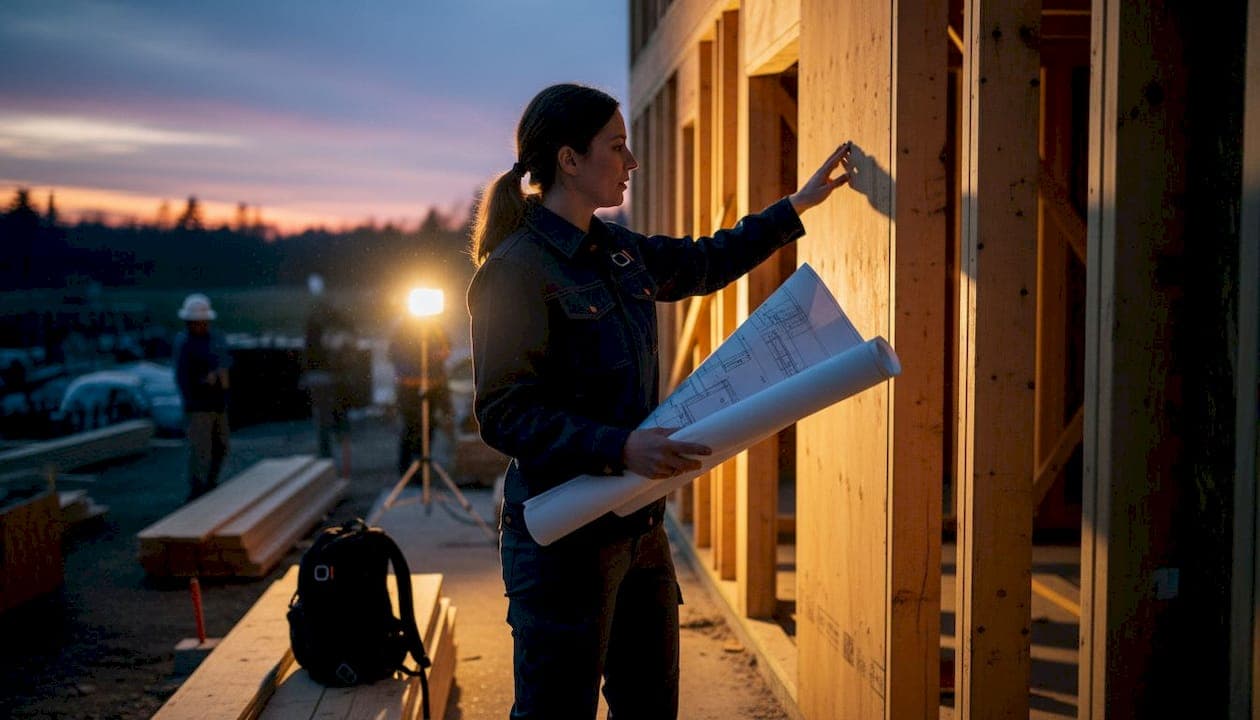
Shear wall load path tracing is the process of following and verifying the continuous lateral load transfer through a wood-framed building's structural elements from the roof diaphragm down to the foundation. Every connection in that chain must carry its share of wind or seismic force without interruption. A single weak link, whether a missing hold-down or an under-nailed blocking panel, can cause the entire lateral force-resisting system to fail. This guide covers the key components, code prerequisites under IRC 2024 and SDPWS, a step-by-step tracing procedure, and the most common mistakes engineers and architects encounter in wood-framed shear wall design.
What are the key components in a shear wall load path?
The complete lateral load path follows four main phases: force collection by diaphragms, horizontal transfer to shear wall lines, vertical drop through wall assemblies, and anchorage to the foundation through hold-downs and anchor bolts. Each phase depends on the one before it. Miss any phase and the load has nowhere to go.
Diaphragms as force collectors
Roof and floor diaphragms act as large horizontal plates that gather lateral forces from wind pressure or seismic acceleration. The diaphragm transfers that accumulated force to the shear walls at its edges through boundary elements called chords and collectors. Collectors, sometimes called drag struts, run parallel to the applied force and deliver load to the shear wall segments along each wall line.
Shear wall framing and sheathing
Once force reaches the shear wall, the structural wood panel sheathing carries it in shear down to the bottom plate. The nailing schedule between sheathing and framing controls how much unit shear the wall can resist. Nailing schedules and hardware ratings are code-specified elements, not field decisions. Blocking at panel edges is required whenever the design relies on full shear transfer between adjacent panels.
Hold-downs, anchor bolts, and foundation connections
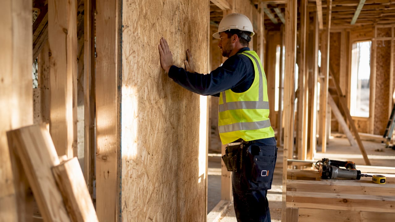
Hold-down devices resist the overturning force at each end of a shear wall segment. Hold-downs must be rated to exceed the calculated unit shear demand and are typically ICC-ES listed hardware installed per the engineer's schedule. Anchor bolts transfer the base shear from the bottom plate into the concrete foundation. Both elements must be sized, spaced, and embedded correctly or the wall rocks rather than resists.
The table below summarizes the four load path phases and the critical connection at each stage.
| Load path phase | Structural element | Critical connection |
|---|---|---|
| Force collection | Roof or floor diaphragm | Chord and collector splices |
| Horizontal transfer | Shear wall top plate | Diaphragm-to-top-plate nailing |
| Vertical transfer | Sheathing and stud framing | Panel edge nailing and blocking |
| Foundation anchorage | Sill plate and footing | Hold-downs and anchor bolts |
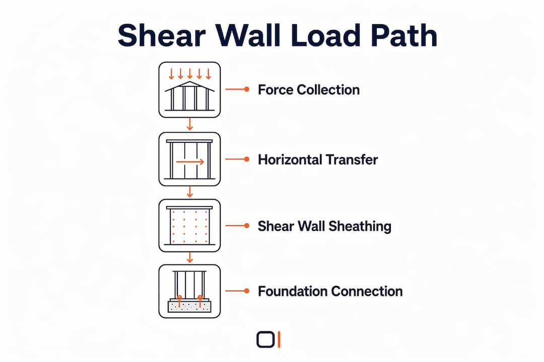
Pro Tip: Sketch the load path on the floor plan before you open any calculation sheet. Identifying collectors and boundary elements visually first prevents missed connections in the math.
Which code requirements guide shear wall load path tracing?
IRC 2024 section R602.10 sets the minimum bracing requirements for wood-framed walls. In low-seismic zones, the code requires a minimum of 25% braced wall length per wall line. In high-demand seismic or wind zones, that figure rises to 50% or more, and braced wall lines must be spaced no more than 35 feet apart. These thresholds directly control how many full-height shear wall segments you need and where you must place them.
Seismic Design Category (SDC) drives hardware selection as much as it drives wall placement. Higher SDCs require ICC-ES listed hold-downs, specific anchor bolt diameters, and engineered nailing schedules rather than prescriptive tables. The SDPWS (Special Design Provisions for Wind and Seismic) provides the unit shear demand calculation method that ties diaphragm forces to shear wall capacity. You cannot complete a code-compliant load path analysis without working through that demand-to-capacity check for each wall line.
Key code checkpoints for load path compliance:
- Confirm braced wall line spacing does not exceed 35 feet per IRC 2024 R602.10.
- Verify shear wall aspect ratios stay within SDPWS limits (typically 2:1 for full capacity, up to 3.5:1 with reduction factors).
- Check that hold-down hardware carries ICC-ES listing at the required load rating.
- Confirm anchor bolt diameter, spacing, and embedment match the engineer's schedule.
- Verify nailing schedules on all sheathing panels match the specified edge and field nail spacing.
Aspect ratio limits deserve special attention. Narrow walls violate aspect ratio limits, which increases deflection and forces load redistribution to adjacent wall segments. That redistribution can overload neighboring walls if the design did not account for it.
How to perform shear wall load path tracing step by step
Systematic tracing is the only way to confirm that every connection in the lateral system is present and adequate. The five steps below apply to both single-story and 2-story shear wall load path analysis in wood-framed construction.
-
Identify lateral load sources. Calculate wind and seismic forces acting on each diaphragm level. Determine the tributary area each diaphragm collects and the total force it must deliver to the shear walls below.
-
Trace horizontal load transfer. Follow the force from the diaphragm field into the chords, then through the collectors to each shear wall line. Confirm that collector connections, including splice plates and straps, are sized for the full collector force.
-
Follow vertical load transfer. Track the unit shear from the top plate down through the sheathing to the bottom plate. Verify that blocking is installed at all horizontal panel joints and that edge nailing matches the schedule.
-
Verify anchorage connections. Check hold-down placement at each end of every full-height segment. Confirm anchor bolt embedment and spacing at the sill plate. Diaphragm-to-top-plate connections are frequent failure points when not detailed properly.
-
Document disruptions and engineered solutions. Flag reentrant corners, large openings, and offset wall lines. Apply Force Transfer Around Openings (FTAO) methods where openings interrupt shear wall segments. FTAO requires careful aspect ratio control to prevent excessive deflection in the segments flanking the opening.
Pro Tip: On 2-story buildings, trace the load path independently for each story, then verify that the upper-story hold-down rod aligns with the lower-story anchor point. Misaligned rods are one of the most common field errors.
The table below lists common tracing challenges and the standard engineering solution for each.
| Tracing challenge | Engineering solution |
|---|---|
| Large window or door opening | Force Transfer Around Openings (FTAO) with strap ties above and below |
| Reentrant corner | Add collector and drag strut to redirect force around the corner |
| Offset wall lines between stories | Design transfer diaphragm at the floor level to bridge the offset |
| Narrow wall segment (high aspect ratio) | Apply SDPWS reduction factor or add adjacent full-height segment |
| Missing hold-down at wall end | Install continuous rod tie-down system or add boundary post with hardware |
What are common mistakes in shear wall load path tracing?
Shear wall design failures most often trace back to connection discontinuities, not panel capacity. The panel itself rarely governs. The nailing, blocking, strapping, and hardware do.
The most frequent errors engineers and architects encounter include:
- Missing hold-downs at wall ends. Walls without hold-downs rock at the base, transferring overturning force to the anchor bolts in a way they were not designed to handle.
- Under-nailed or unblocked panel edges. Skipping edge blocking drops the effective unit shear capacity of the wall, often below the demand without any visible sign during framing inspection.
- Improper strapping between floors. Floor-to-wall interfaces are frequent failure points when strap ties are omitted or installed with insufficient nailing.
- Aspect ratio violations. Tall, narrow wall segments deflect more than the design assumes, pushing excess load to adjacent segments and potentially overloading them.
Wood shrinkage adds a layer of complexity in multi-story buildings. Shrinkage impacts load path continuity by introducing cumulative slack in individual hold-down brackets stacked across multiple floors. Continuous steel rod tie-down systems reduce that slack and maintain load path integrity far better than stacked individual brackets. For buildings with three or more wood-framed stories, continuous rods are the standard practice, not an upgrade.
Lateral force-resisting systems are only as strong as their weakest connection. A shear wall panel rated for 800 plf does nothing if the diaphragm-to-top-plate nailing delivers only half that force to the wall. Trace every connection, not just the panel.
Pro Tip: During construction observation, verify hold-down anchor rod embedment depth before the concrete pour. Correcting embedment after the pour requires coring or epoxy anchors, both of which add cost and schedule risk.
Key Takeaways
Accurate shear wall load path tracing requires verifying every connection from the diaphragm to the foundation, because the lateral system's capacity equals its weakest link.
| Point | Details |
|---|---|
| Four-phase load path | Forces move from diaphragm to shear wall to foundation through four distinct, connected phases. |
| Code minimums matter | IRC 2024 R602.10 sets bracing percentages and wall line spacing that define the minimum compliant design. |
| Connections govern capacity | Panel ratings are secondary; nailing, blocking, hold-downs, and anchor bolts control system performance. |
| Continuous rods for multi-story | Stacked individual hold-downs accumulate slack from wood shrinkage; continuous rods preserve load path integrity. |
| Document disruptions early | Reentrant corners and large openings require engineered solutions like FTAO and drag struts identified at the design phase. |
Why connection sequencing is the real skill in load path tracing
After years of reviewing wood-framed lateral systems, I have come to one clear conclusion: most engineers understand shear wall panels. Far fewer think carefully about connection sequencing, and that gap is where buildings get into trouble.
The hold-down embedment issue is the one I see most often during construction observation. The rod is present, the hardware is specified, but the embedment depth is short by an inch or two because no one checked before the pour. That single oversight can reduce the hold-down's rated capacity enough to put the wall out of compliance. It is a fixable problem before the pour and a very expensive one after.
I also advocate strongly for identifying chords and collectors at the earliest design phase, not as a cleanup task after the wall layout is set. Complex floor plans with large open areas or L-shaped footprints create collector paths that are long, heavily loaded, and easy to miss. When you find the collector late, you often find that the framing cannot accommodate the required connection without significant revision.
For multi-story wood construction, I have shifted to recommending continuous rod tie-down systems as a default rather than a special case. The shrinkage-related slack in stacked brackets is real, measurable, and cumulative. Continuous rods eliminate that problem at a cost that is almost always justified by the reduction in inspection callbacks and field corrections.
The engineers who do this work well treat load path tracing as a discipline, not a checklist. They trace every connection, document every disruption, and verify every hardware specification before the project leaves the design office.
— Evalin
ShearWise Pro: built for shear wall load path analysis
Organizing shear wall calculations across multiple wall lines, stories, and load cases is where projects lose time and introduce errors. ShearWise Pro addresses that directly.

ShearWise Pro is a focused shear wall calculator built for 1-story and 2-story wood-framed buildings. The platform organizes wall lines, full-height segments, hold-down forces, transfer straps, and story drift checks in one place. It generates clean PDF reports formatted for review coordination, so your calculations are documented and ready for plan check or peer review. Engineers and architects working on wood-framed lateral systems can use ShearWise Pro to verify load path compliance and reduce the manual effort of tracking connections across multiple wall lines. You can review a sample ShearWise report to see how the output is structured before committing to a workflow change.
FAQ
What is shear wall load path tracing?
Shear wall load path tracing is the process of following lateral forces from the roof or floor diaphragm through shear walls and connections down to the foundation. The goal is to verify that every connection in the chain is present, sized correctly, and code-compliant.
What are the four phases of a shear wall load path?
The four phases are force collection by the diaphragm, horizontal transfer to shear wall lines through chords and collectors, vertical transfer through sheathing and framing, and foundation anchorage through hold-downs and anchor bolts.
How does IRC 2024 affect shear wall design?
IRC 2024 section R602.10 requires minimum braced wall percentages ranging from 25% in low-seismic zones to 50% or more in high-demand areas, with braced wall lines spaced no more than 35 feet apart.
Why do continuous rod tie-downs outperform stacked hold-down brackets?
Wood shrinkage in multi-story buildings creates cumulative slack in stacked individual brackets, reducing load path continuity. Continuous steel rods span multiple floors without that slack, maintaining consistent hold-down performance.
What is Force Transfer Around Openings (FTAO)?
FTAO is an engineered method that uses strap ties above and below wall openings to transfer shear around the opening without adding wall length. It requires careful aspect ratio control on the flanking wall segments to prevent excessive deflection.