

A lateral analysis summary is a concise deliverable that reports a structure's resistance to horizontal loads and the key numerical checks engineers and reviewers need to make design decisions. At minimum, it includes base shear, story drift, member forces, and load path distribution, plus the controlling load case, code references, and a clear statement of modeling assumptions. The summary supports permit submittals, design coordination, and retrofit screening — it is the one document a plan reviewer or project manager should be able to read in under five minutes and confirm that the lateral system works.
Mandatory items in every lateral analysis summary:
- Base shear (V = CsW) and the governing load combination
- Per-story shear and maximum story drift (absolute and as a percentage of story height)
- Member shear and moment envelopes for critical elements
- Load path description from diaphragm to foundation
- Controlling analysis method and code edition (ASCE 7, IBC)
- Key modeling assumptions (diaphragm type, stiffness modifiers, mass distribution)
- Demand/capacity (D/C) ratios for governing members, with D/C > 1.0 flagged
- For retrofit projects, the IBC 10% rule screening comparison and baseline record
ShearWise Pro automates the shear wall components of this summary for 1–2 story wood buildings, including wall line outputs, hold-down forces, story drift checks, and PDF report generation.
Table of Contents
- Which lateral analysis method should you use?
- Modeling choices that change your lateral results
- What numbers belong in a lateral analysis summary
- How to read the results: required checks and decision points
- Common modeling and reporting mistakes to avoid
- A copy-ready template for your lateral analysis summary
- How ShearWise Pro fits into a wood building lateral summary
- Key references and code clauses to cite in your summary
- Key Takeaways
- The judgment calls that separate a good summary from a defensible one
- ShearWise Pro speeds up shear wall reporting for wood buildings
- Useful sources for lateral analysis summaries
Which lateral analysis method should you use?
Choosing the right method determines what your summary needs to report and how much backup documentation is required. The four methods below cover most building projects.
Equivalent Lateral Force (ELF) / Lateral Force Method The ELF procedure from ASCE 7 Section 12.8 distributes a static base shear up the building height using a vertical distribution factor. It is permitted for most low-rise, regular structures and is the default starting point for wood-framed buildings, light steel frames, and masonry up to moderate height. The summary for an ELF analysis is straightforward: report Cs, W, V, and the vertical distribution per floor.
Response Spectrum Analysis (RSA) RSA is required by ASCE 7 when the building has certain irregularities or exceeds height limits for ELF. It uses modal superposition with a design spectrum and produces modal participation factors, effective modal mass, and combined story forces. Your summary must include the number of modes considered, the total modal mass captured (ASCE 7 requires at least 90%), and the scaling factor if results are scaled to the ELF base shear minimum.
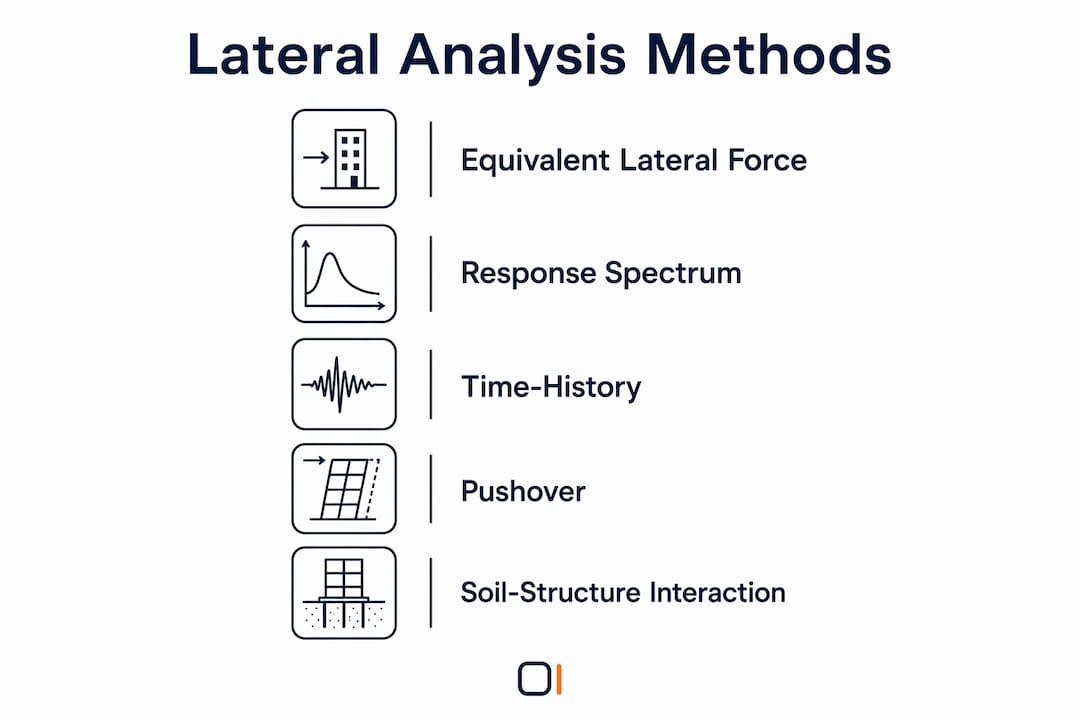
Time-History Analysis Time-history procedures, both linear and nonlinear, are required for seismically isolated structures and performance-based designs. They produce the most detailed output but also the most data to distill. The summary should report peak story drifts, peak base shear, and the suite of ground motions used, with a note on whether median or maximum values govern.
Pushover / Simplified Nonlinear (Retrofit) Pushover analysis is common for existing building evaluations under ASCE 41. It identifies the target displacement and the sequence of member yielding. Summaries for pushover runs should report the capacity curve, target displacement, and performance point relative to the selected performance objective.
Soil-Structure Interaction / p-y Methods (Foundation Lateral) For deep foundations, lateral analysis using p-y curves computes pile head shear, moment, lateral displacement, and mobilized soil resistance. These outputs differ substantially from building-level summaries and require grid-point reporting.
When does ASCE 7 require dynamic procedures? ASCE 7 Section 12.6 triggers RSA or time-history when a structure has horizontal or vertical irregularities (Table 12.3-1 and 12.3-2), exceeds the height limits in Table 12.6-1, or is assigned to Seismic Design Category D, E, or F with specific conditions. If your building qualifies for ELF, document that explicitly in the summary.
Modeling choices that change your lateral results
Modeling assumptions drive load distribution more than software capability does. The choices below are where most summary errors originate.

Diaphragm treatment
The diaphragm assumption controls how story shear distributes to vertical elements. Rigid diaphragms distribute load in proportion to relative stiffness; flexible diaphragms distribute load by tributary area. Semi-rigid modeling requires plate elements and is the most accurate but also the most sensitive to mesh quality. For wood-framed buildings, ASCE 7 Section 12.3.1 provides prescriptive criteria for classifying diaphragms as flexible. Document the classification and the basis for it.
Diaphragm chord and collector elements must be explicitly modeled or their forces must be hand-calculated and added to the summary. Omitting them is one of the most common load path gaps.
Element types and stiffness modifiers
Line elements (beams, columns, braces) are appropriate for most steel and concrete frames. Plate or shell elements are needed for shear walls and slabs when semi-rigid diaphragm behavior is modeled. Stiffness modifiers (ACI 318 Table — for concrete, or project-specific values) reduce effective stiffness to account for cracking and must be documented. Using gross section properties without modifiers overstates stiffness and understates drift.
Mass distribution and torsion
Seismic mass should be assigned at each floor level based on tributary dead load plus applicable live load fractions per ASCE 7 Section 12.7.2. Accidental torsion (5% eccentricity per ASCE 7 Section 12.8.4.2) must be applied unless the building qualifies for an exception. Report the center of mass and center of rigidity coordinates and the resulting eccentricity ratio.
Boundary and support conditions
Fixed vs. pinned base assumptions change column moments and drift significantly. For wood buildings, pin-base columns are typical unless a moment frame is explicitly detailed. Confirm that support conditions in the model match the actual connection details.
Compact modeling QA checklist:
- Diaphragm type documented and justified per ASCE 7 Section 12.3.1
- Stiffness modifiers applied and listed in assumptions
- Seismic mass verified against gravity load takeoff
- Accidental torsion applied at each level
- Support conditions match connection details
- All load paths traced from roof to foundation
- Modal mass participation ≥ 90% confirmed (for RSA)
Pro Tip: Before trusting any software output, run a manual base shear check using V = CsW and compare it to the model's reported base shear. A discrepancy greater than 5% usually points to a mass input error or an incorrect seismic weight assignment — not a software bug.
What numbers belong in a lateral analysis summary
The table below shows the core outputs, preferred units, and acceptance benchmarks for a typical building lateral summary.
| Output | Units | Acceptance Benchmark |
|---|---|---|
| Base shear (V) | kips | V = CsW; compare to hand check |
| Per-story shear | kips per story | Decreasing from roof to base |
| Maximum story drift (Δ) | in. and % story height | ≤ ASCE 7 Table 12.12-1 limits |
| Modal participation factor | % of total mass | ≥ 90% cumulative (RSA) |
| Member shear envelope | kips | D/C ≤ 1.0; flag exceedances |
| Member moment envelope | kip-ft | D/C ≤ 1.0; flag exceedances |
| Overturning moment | kip-ft | Compare to foundation capacity |
| Torsional amplification (Ax) | dimensionless | Ax > 1.0 triggers amplification |
| Foundation reactions | kips, kip-ft | Match geotechnical report limits |
For foundation lateral analysis, standard report fields also include depth, bending moment, lateral displacement, rotation, and percentage of mobilized soil resistance at each grid point.
Rounding and formatting conventions:
- Round base shear and story shear to the nearest 0.1 kip.
- Report story drift to three decimal places in inches and two decimal places as a percentage.
- Highlight any D/C ratio above 1.0 in red or bold in the summary table.
- Values requiring detailed backup (member moment envelopes, full modal output) go in appendices, not on the summary page.
ASCE 7 drift limits to check: Story drift limits under ASCE 7 Table 12.12-1 vary by occupancy category and structural system. For most wood-framed residential buildings (Risk Category II), the allowable story drift is 0.025 times the story height. Always state the applicable limit and the controlling story in the summary.
How to read the results: required checks and decision points
A summary that lists numbers without flagging pass/fail status is incomplete. Use this checklist to confirm the analysis is both correct and sufficient.
Drift checks:
- Compare maximum computed story drift to the ASCE 7 Table 12.12-1 limit for the applicable Risk Category and structural system.
- For wood diaphragms, run a separate diaphragm deflection check per AWC SDPWS Section 4.2.2 when the diaphragm span-to-depth ratio exceeds 3:1 or when the diaphragm is classified as flexible.
- Report both the absolute drift (in.) and the drift ratio (drift / story height).
Demand vs. capacity checks:
- Compute D/C ratios for all critical members (shear walls, collectors, drag struts, moment frame members).
- Flag any D/C > 1.0 in the summary and note whether a redesign or supplemental analysis is pending.
- For shear walls in wood buildings, verify unit shear demand against the allowable unit shear from AWC SDPWS Table 4.3A or 4.3B.
Load path continuity:
- Trace the shear load path from roof diaphragm through collectors, shear walls, hold-downs, and into the foundation.
- Confirm that every transfer element (strap, ledger, drag strut) has a calculated demand and a specified connection.
- Note any gaps in the load path as open items requiring resolution before permit submittal.
Sanity checks:
- Modal mass participation should reach at least 90% of total seismic mass. If it does not, add more modes.
- Check for unexpected zero loads on shear walls or columns — these usually indicate a connectivity error in the model.
- Verify sign conventions: lateral loads applied in the positive X direction should produce positive reactions at the base on the windward side. Reversed signs are a common indicator of an incorrect load application.
- ETABS and similar FEM tools report story drifts and relative stiffness that can be cross-checked against hand calculations using ASCE 7 limits.
Common modeling and reporting mistakes to avoid
The most consequential errors in lateral summaries are not math errors — they are assumption errors that the software processes without complaint.
Frequent pitfalls:
- Wrong diaphragm assumption: Modeling a wood-framed floor as rigid when it qualifies as flexible per ASCE 7 Section 12.3.1 shifts load to stiffer walls and can underload flexible ones.
- Omitted continuity members: Collectors and drag struts that exist on the drawings but are not modeled leave the load path incomplete.
- Improper support constraints: Pinning a column base that is actually moment-connected, or vice versa, changes both drift and member forces.
- Neglected seismic mass: Omitting heavy mechanical equipment, green roofs, or storage loads from the seismic weight underestimates base shear.
- Arbitrary stiffness changes: Reducing wall stiffness without documentation to "tune" the model distorts load distribution and is indefensible at plan review.
Stepwise QA checklist:
- Model inputs: Confirm geometry, member sizes, and material properties match the current drawing set.
- Mass and rigid body check: Sum the seismic weight from the model and compare to a hand takeoff. Difference should be under 5%.
- Modal review: Check modal shapes visually. The first two modes should be translational; the third should be torsional for a regular building. Unexpected coupling indicates a modeling error.
- Results sanity: Verify base shear against V = CsW. Check that story shears decrease from roof to base.
- Documentation of assumptions: Every non-default input (stiffness modifier, diaphragm type, mass assignment) must appear in the assumptions section of the summary.
Pro Tip: If a reviewer questions a result, the fastest way to defend it is to show the hand-check comparison. Keep a one-page calculation sheet alongside the summary that reproduces base shear, controlling drift, and at least one critical D/C ratio by hand. If the hand check and the model agree within 10%, the model is almost certainly set up correctly.
A copy-ready template for your lateral analysis summary
The one-page summary below is a format you can paste directly into a project report. Appendices carry the full output; the summary page carries only what a reviewer needs to confirm adequacy.
Summary page structure
| Section | Content |
|---|---|
| Project ID and date | Project name, address, permit number, analysis date, revision number |
| BLUF statement | One sentence: system type, governing load case, controlling check, and pass/fail verdict |
| Controlling load case | Load combination (e.g., 1.0D + 1.0E per ASCE 7) and governing direction |
| Headline numbers table | Base shear, max story drift, controlling D/C ratio, overturning moment |
| Per-story summary table | Story, height, story shear (kips), drift (in.), drift ratio (%), D/C max |
| Critical member list | Member ID, type, demand, capacity, D/C ratio |
| Key modeling assumptions | Diaphragm type, stiffness modifiers, mass basis, support conditions |
| Code citations | ASCE 7 edition and sections, IBC edition, material standards (AISC, ACI, AWC) |
| Reviewer signature and date | Licensed engineer's stamp or signature block |
BLUF statement example
Appendix checklist
- Full model output files (ETABS, RISA, or equivalent)
- Complete modal summary (frequencies, mode shapes, participation factors)
- Member-level design checks for all critical elements
- Load path diagrams showing force flow from roof to foundation
- Sensitivity runs (e.g., ±10% stiffness variation, alternate diaphragm assumption)
- Soil interaction notes or geotechnical report reference
Figures on page 1: Include a plan view showing shear wall locations and a building elevation showing story heights and load application points. Detailed mode shapes, force diagrams, and deflected shapes go in the appendix.
Tailoring for audience: For a technical peer reviewer, include the full assumptions list and code clause citations. For a project manager or contractor, lead with the BLUF statement and the shear wall schedule — they need to know what to build, not how the math was done.
How ShearWise Pro fits into a wood building lateral summary
For 1–2 story wood-framed buildings, ShearWise Pro automates the shear wall components of the lateral summary directly.
What ShearWise Pro produces:
- Wall line organization with opening reductions and full-height segment identification
- Unit shear demand per wall line and allowable capacity per AWC SDPWS
- Hold-down forces and transfer strap demands at each wall line
- Story drift checks with pass/fail status
- Clean PDF reports formatted for permit submittal and review coordination
How to integrate outputs into the one-page template:
The ShearWise Pro PDF report maps directly to the critical member list and per-story summary sections of the template above. Copy the wall line unit shear demands and D/C ratios into the headline numbers table. The hold-down and strap forces feed the critical member list. Story drift outputs populate the per-story drift columns.
Manual checks still required:
- Diaphragm design and chord/collector force calculations (outside ShearWise Pro's scope)
- Seismic weight takeoff and base shear calculation per ASCE 7 Section 12.8
- Foundation connection design and geotechnical coordination
- Load path tracing from diaphragm to foundation for the full building
Scope limitation: ShearWise Pro is designed for 1–2 story wood buildings. For taller structures, concrete or steel frames, irregular buildings requiring RSA or time-history analysis, or any project requiring full building FEM, a separate analysis platform is required.
Pro Tip: Use the ShearWise Pro sample report as a formatting reference when setting up your own summary template. The output structure maps cleanly to the per-story and critical member sections described above.
Key references and code clauses to cite in your summary
Every lateral analysis summary should carry a references section that justifies the method chosen and the acceptance criteria applied. The table below lists the core citations.
| Standard | Relevant Sections | Purpose |
|---|---|---|
| ASCE 7-22 | 12.3, 12.6, 12.7, 12.8, 12.9, 12.12 | Seismic design criteria, method selection, drift limits |
| IBC 2021 | 1613, 1604.3 | Seismic and wind load adoption, general structural requirements |
| AWC SDPWS-2021 | 4.2, 4.3 | Wood diaphragm and shear wall design values |
| ACI 318-19 | — | Stiffness modifiers for concrete members |
| AISC 360-16 | Chapter C, H | Steel frame stability and combined loading |
| AASHTO LRFD (for bridges/foundations) | — | Drilled shaft lateral resistance |
Suggested phrasing for method justification:
When using ELF, write: "The Equivalent Lateral Force procedure is permitted per ASCE 7-22 Section 12.6 Table 12.6-1 because the structure is assigned to SDC [X], is [height] ft tall, and has no horizontal or vertical irregularities per Tables 12.3-1 and 12.3-2."
When using RSA, note the number of modes included, the cumulative mass participation achieved, and the scaling factor applied if base shear was scaled to the ELF minimum per ASCE 7 Section 12.9.1.4.
Additional references for specialized topics:
- Pile lateral analysis using p-y methods: cite the geotechnical software documentation and the applicable AASHTO or ASCE standard.
- Soil-structure interaction: ASCE 7 Chapter 19 and the project geotechnical report.
- Diaphragm deflection: AWC SDPWS Section 4.2.2 and the project-specific nail schedule.
- Retrofit screening using the IBC 10% rule: document the existing vs. new lateral load comparison and the baseline analysis method.
Key Takeaways
A lateral analysis summary is only as useful as its clarity: the BLUF statement, controlling load case, and flagged D/C ratios must be visible on page one so any reviewer can confirm adequacy without digging into appendices.
| Point | Details |
|---|---|
| Lead with the BLUF | State system type, governing load case, max drift, and pass/fail verdict in one sentence on page one. |
| Report drift two ways | Always include story drift as both an absolute value (in.) and a ratio (drift / story height) against the ASCE 7 Table 12.12-1 limit. |
| Flag every D/C > 1.0 | Highlight demand/capacity ratios above 1.0 in the summary table; note whether redesign is pending. |
| Document all assumptions | List diaphragm type, stiffness modifiers, mass basis, and support conditions — every non-default input needs a written justification. |
| ShearWise Pro for wood buildings | For 1–2 story wood projects, ShearWise Pro automates wall line shear, hold-down forces, and drift checks, feeding directly into the critical member and per-story sections of the summary template. |
The judgment calls that separate a good summary from a defensible one
Most lateral analysis summaries fail peer review not because the math is wrong, but because the assumptions are undocumented and the reviewer cannot tell whether the engineer made a deliberate choice or just accepted a software default.
The ELF procedure is appropriate for the vast majority of low-rise wood and light-frame buildings. Escalating to RSA when ELF is permitted adds cost and complexity without improving accuracy for regular structures. The judgment call is knowing when a building's irregularity or height genuinely triggers the need for a higher-level method — and documenting that decision explicitly rather than defaulting to the more complex approach to appear thorough.
For retrofit projects, a preliminary lateral summary using the IBC 10% rule can save significant time and cost. Record the baseline clearly: what analysis method was used for the existing building, what loads were assumed, and how the comparison was made. A defensible screening is one a plan reviewer can reproduce from the summary alone.
Junior engineers often underweight the assumptions section. In practice, a reviewer who disagrees with an assumption will reject the summary regardless of how clean the output tables look. Write the assumptions section as if you are explaining your choices to a skeptical peer, not filling in a form.
A well-written BLUF for a small renovation might read: "The lateral system for this single-story wood addition (Risk Category II, SDC B) was evaluated using the Equivalent Lateral Force procedure per ASCE 7-22 Section 12.8. The addition increases the building's lateral demand by less than 10% per IBC 2021 Section 3403.3; no upgrade to the existing system is required. All new shear walls are adequate with D/C ≤ 0.88." That is the standard to aim for.
ShearWise Pro speeds up shear wall reporting for wood buildings
For engineers producing lateral summaries on 1–2 story wood-framed projects, the shear wall calculation phase is often the most time-consuming part. ShearWise Pro cuts that time by organizing wall lines, computing unit shear demands, calculating hold-down forces and transfer strap requirements, running story drift checks, and generating a formatted PDF report ready for permit submittal.

The PDF output maps directly to the critical member list and per-story summary sections of the one-page template in this guide. You handle the BLUF statement, the base shear calculation, and the load path narrative; ShearWise Pro handles the wall-by-wall arithmetic and the report formatting. The platform is scoped to 1–2 story wood buildings, so it is the right tool for residential design, small commercial wood-frame projects, and retrofit screening on light-frame structures. For projects requiring full building FEM or dynamic analysis, a separate platform is still needed.
View a sample ShearWise report to see how the outputs map to the summary template, or sign up to try ShearWise Pro and run your first wall line calculation today.
Useful sources for lateral analysis summaries
Short annotations for the core references to cite or link from a lateral analysis summary.
Code justification sources:
- ASCE 7-22 (asce.org): Sections 12.3, 12.6, 12.7, 12.8, 12.9, and 12.12 cover method selection, seismic weight, load distribution, and drift limits. Cite the specific section and table for every acceptance criterion you apply.
- IBC 2021 (iccsafe.org): Section 1613 adopts ASCE 7 seismic provisions; Section 1604.3 covers load combinations. Use for permit submittal code basis.
- AWC SDPWS-2021 (awc.org): Tables 4.3A and 4.3B for wood shear wall capacities; Section 4.2.2 for diaphragm deflection. Required citation for any wood lateral summary.
Modeling guidance sources:
| Source | Best For |
|---|---|
| STRUCTURE Magazine lateral analysis article | Black box risks, diaphragm modeling, QA approach |
| WoodWorks lateral analysis resource | Wood-specific diaphragm and shear wall detailing |
| OPILE lateral output documentation | Foundation/pile lateral grid-point reporting |
| ADOT drilled shaft lateral policy | AASHTO LRFD drilled shaft lateral analysis procedure |
Internal ShearWise Pro resources for deeper reading:
- Lateral load distribution for engineers: diagrams and per-story force flow explanations useful for the load path section of a summary.
- Wood frame building lateral analysis guide: practical sample calculations for wood-framed projects.
- Lateral design software explained: how software outputs map to construction deliverables.