
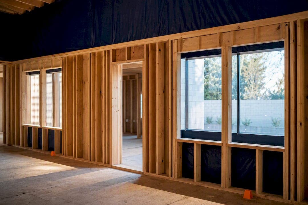
A perforated shear wall (PSW) is a sheathed wood wall with openings that gets designed as one continuous lateral system, corrected by an opening adjustment factor, Co. The design action that follows from that definition is simple: size the anchorage for the maximum unit shear, vmax, concentrated at the wall ends, not at every opening. Before you calculate anything, confirm the wall meets the code's height and elevation limits for the perforated method.
TL;DR:
- The perforated shear wall method relies on a single adjusted shear value, Co, at the wall ends, requiring full-height shear segment identification for design.
- Confirm the wall's height, uniform elevation, and that openings are within the wall line to qualify for this method, with maximum allowable shear around 686 plf for wind loads.
- Proper interpolation of Co from the code table is critical, as errors in opening height measurement or v values directly affect shear capacity and anchor sizing.
- Use the software ShearWise Pro to automate calculations, ensure code compliance, and generate permit-ready reports, reducing manual errors and saving time.
- Field quality control, especially accurate opening measurements and anchor placement, along with moisture control at the base, are vital for long-term performance of perforated shear walls.
Table of Contents
- What a Perforated Shear Wall Is and When to Use the PSW Method
- Code Provisions and Numeric Limits to Check Before You Design
- How to Design a Perforated Shear Wall Step by Step
- Anchorage, Collectors, and Detailing for Perforated Shear Walls
- Worked Example: Two-Story Perforated Shear Wall Calculation
- Common Pitfalls and QA Checks in Perforated Shear Wall Design
- How ShearWise Pro Handles Perforated Shear Wall Calculations
- Material Considerations for Perforated Shear Wall Construction
- Construction Techniques and Quality Control for Perforated Shear Walls
- Long-Term Durability Factors for Perforated Shear Walls
- Research Trends in Perforated Shear Wall Design
- Practical Trade-Offs When Specifying Perforated Shear Walls
- Automate Your Perforated Shear Wall Calculations
- Sources
What a Perforated Shear Wall Is and When to Use the PSW Method
The perforated shear wall method treats a wall line with door and window openings as a single lateral element instead of a series of isolated segments. You calculate one adjusted shear value for the whole wall line using the opening adjustment factor, Co, rather than designing each full-height segment independently. That is the core distinction from the segmented shear wall method, which requires you to isolate each full-height sheathed segment and design it, and its hold-downs, on its own.
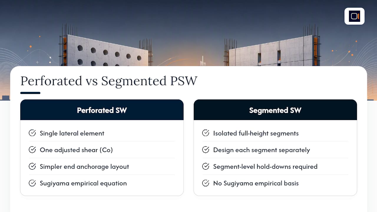
The PSW approach traces back to Sugiyama's empirical equation, developed to account for the partial overturning resistance that sheathing above and below openings still provides, even when it is not a full-height segment. That empirical basis is why the method is intentionally conservative in how it distributes anchorage forces. It gives up some precision at the segment level in exchange for a simpler, safer anchorage layout at the wall ends.
The method only works within specific limits, including limitations on wall height and uniformity of top and bottom elevations across the wall line, as well as allowable unit shear values limited by applicable material tables. Openings must be contained within the wall line to maintain continuous framing.
Segmented and force-transfer-around-openings (FTAO) methods remain the better fit when those constraints do not hold.
Code Provisions and Numeric Limits to Check Before You Design
Before you run a single calculation, confirm the wall qualifies under the applicable code section. UpCodes summarizes the perforated shear wall provisions that most jurisdictions reference through IBC Section 2305.3.7.2, and the numeric limits there are non-negotiable gatekeepers, not suggestions.
Four checks come first:
- Wall height, h, must not exceed the maximum allowed height by code, with uniform top-of-wall and bottom-of-wall elevations across the entire line.
- The percentage of full-height sheathing determines Co, and intermediate percentages between listed table values are permitted to be interpolated rather than rounded down.
- Allowable unit shear is capped at the material table value. The commonly cited wind-design baseline runs 490 plf, and some AWC guidance permits a 1.4 multiplier for wind cases, bringing the adjusted allowable to roughly 686 plf.
- Offsets in framing or elevation anywhere along the wall line disqualify the perforated method for that line; you'd need to split it into separate PSW lines or switch to segmented design.
Reading the Co table correctly matters more than most engineers assume. Interpolation between two known percentages of full-height sheathing is allowed, but rounding to the nearest listed value in either direction introduces error that compounds through the rest of the calculation. Get this input wrong, and every downstream number, from Vperforated to chord force, inherits that mistake.
How to Design a Perforated Shear Wall Step by Step
Designing a perforated shear wall follows a fixed sequence. Skip a step or reorder it, and the anchorage sizing will not match what the wall actually needs.
- Compute the sum of full-height sheathed lengths, ΣLi. Identify every wall segment that runs the full height of the wall with no openings interrupting it. Segments that don't meet the minimum aspect ratio requirement, typically a height-to-width ratio tied to Hwall/2 or Hwall/3 depending on material, get excluded from ΣLi even if they run full height.
- Measure the maximum unrestrained opening clear height. This is the tallest opening in the wall line, measured from the header underside to the top of the sill or floor. Engineers frequently misread this dimension by measuring to the rough opening instead of the clear opening, which throws off the percent full-height sheathing calculation that follows.
- Calculate percent full-height sheathing. Divide ΣLi by the total wall length, then use that percentage, alongside the maximum opening height ratio, to enter the Co table.
- Read or interpolate Co, then compute Vperforated using Vperforated = v · Co · ΣLi, where v is the tabulated unit shear capacity for the sheathing and fastening schedule you specified.
- Determine vmax, the peak unit shear at the wall ends, and apply that value as a uniform uplift, t = vmax, along the bottom plate anchorage for the full wall line.
- Compute tension chord force, T, and compression chord force, C, at each end of the wall line, factoring in the overturning moment generated by the applied shear and the wall's aspect ratio.
- Verify collectors and the continuous load path connecting this wall line to the diaphragm above and the foundation below, and check whether multiple stories stack forces that the ground-floor anchorage must carry cumulatively.
Pro Tip: Run the percent full-height sheathing number twice, once by hand and once through your software, before you touch the Co table. A single misread opening height cascades through Vperforated, vmax, and every anchor you spec.
Anchorage, Collectors, and Detailing for Perforated Shear Walls
The anchorage decisions you make from vmax determine whether the wall performs the way the calculation promised. Perforated shear wall design consolidates hold-downs to the two ends of the entire wall line, which is the single biggest practical difference from segmented design, where every full-height segment needs its own hold-down pair.
A few detailing rules follow directly from that consolidation:
- Anchor bolts resisting overturning should sit close to the segment ends. Testing on long shear walls with openings shows anchors performing as designed when placed within about 12 inches of the ends.
- Bottom plate anchorage across the wall line gets sized for the uniform uplift, t = vmax, not the average shear. This is intentionally conservative since actual shear distribution along the wall is rarely perfectly uniform.
- Collectors need to be sized for the full transfer force at each end, and checked separately from the hold-down capacity itself.
- Tension and compression chords carry the overturning couple, and in multi-story construction, those chord forces sum from the upper story down, meaning your ground-floor chord has to carry both stories' contributions.
Continuous rim joist or blocking between joists are the two common options for transferring chord forces at floor lines. Which one you choose depends on framing direction and whether the joists run parallel or perpendicular to the wall line, per AWC's detailing guidance.
Worked Example: Two-Story Perforated Shear Wall Calculation
Consider a 24-foot-long, 9-foot-tall wall line on the second story of a wood-framed structure, with two window openings interrupting the sheathing. The code table gives an allowable unit shear, v, of 260 plf for the specified sheathing and nailing schedule under wind loading.
- Full-height sheathed segments total 14 feet (ΣLi = 14 ft) after excluding a short 2-foot segment that fails the minimum aspect ratio check.
- Percent full-height sheathing = 14 ÷ 24 = 58%.
- Maximum unrestrained opening height measures 5 feet, giving a height ratio of 5/9, or about 56% of wall height.
- Interpolating Co from the code table for 58% full-height sheathing and that opening height ratio yields approximately Co = 0.62.
- Vperforated = v · Co · ΣLi = 260 × 0.62 × 14 ≈ 2,257 lb total shear resisted by the wall line.
- vmax at the wall ends works out to roughly 420 plf once the overturning distribution is applied, which sets the uniform uplift, t, for the bottom plate anchorage along the full 24-foot line.
| Parameter | Value |
|---|---|
| Wall length | 24 ft |
| Wall height | 9 ft |
| ΣLi (full-height sheathing) | 14 ft |
| Percent full-height sheathing | 58% |
| Interpolated Co | 0.62 |
| Allowable v | 260 plf |
| Vperforated | ~2,257 lb |
| vmax (uniform uplift, t) | ~420 plf |
The resulting tension and compression chord forces at each end depend on the overturning moment arm, roughly the wall length, and should be checked against the story above's cumulative load before finalizing hold-down hardware. Story drift should still get a separate check against the applicable deflection limit; a low vmax doesn't guarantee the wall meets drift criteria under a governing wind or seismic load combination.
Common Pitfalls and QA Checks in Perforated Shear Wall Design
Most PSW errors trace back to one of three inputs, not the equation itself.
- Misidentified opening height. Measuring to the rough opening instead of the clear unrestrained height inflates or deflates the Co lookup.
- Wrong v entry. Pulling the allowable unit shear from the wrong table row, wrong nailing schedule, or wrong load type (wind versus seismic) throws off Vperforated before Co even enters the picture.
- Forgetting the uniform elevation requirement. A wall line with a stepped top plate or offset sill disqualifies the perforated method entirely, even if every other number checks out.
Before sign-off, verify the Co interpolation falls between two adjacent table values, confirm collector continuity across the full wall line, and check anchor embedment and spacing against the manufacturer's tested values.
Pro Tip: Keep a printed copy of the Co table next to your calculation sheet during peer review. Catching an interpolation error on paper takes thirty seconds; catching it after the permit set is stamped takes a resubmittal.
How ShearWise Pro Handles Perforated Shear Wall Calculations
ShearWise Pro automates the parts of PSW design most prone to manual error: Co interpolation, Vperforated and vmax calculations, and the resulting uplift and chord distributions, then compiles the output into a permit-ready PDF.
- The software enforces geometry inputs, including the 20-foot height limit, so you catch a disqualifying condition before you've built out the full calculation.
- It won't fix a wrong opening height or an incorrect v entry. You still verify governing load case, code edition, and the wall geometry you typed in, exactly as Structure Magazine notes for any shear wall software.
- Tutorial walkthroughs show the PSW workflow end to end for 1- and 2-story wood buildings.
Material Considerations for Perforated Shear Wall Construction
Wood structural panel sheathing, oriented strand board (OSB) or plywood, remains the standard material for perforated shear walls, and the allowable unit shear value, v, in your Co calculation depends directly on which one you specify. OSB and plywood carry different tabulated shear values at the same nominal thickness, and mixing panel types within one wall line without separate calculations for each zone creates a documentation gap during review.
Fastener schedule matters just as much as panel choice. Nail size, spacing, and edge distance all feed into the tabulated v value you pull from the code table, and a denser nailing schedule at panel edges can push a wall into a higher allowable shear category without changing the panel itself. Framing lumber grade and stud spacing also factor in indirectly: undersized studs or wide spacing can reduce panel buckling resistance under lateral load, even when the sheathing and fasteners meet the letter of the table.
Gypsum wallboard is sometimes used as supplemental interior sheathing on lower-demand wall lines, but its shear contribution is limited compared to wood structural panels, and most engineers reserve it for combination assemblies rather than as the primary lateral resisting material in a PSW line. Sill plate material and pressure treatment become relevant wherever the anchorage terminates at a slab or foundation, since that connection carries the full uniform uplift, t = vmax, calculated for the wall line. Specifying a treated sill without checking bolt hole tear-out capacity under that uplift is a common gap between the calculation sheet and the field detail.
Construction Techniques and Quality Control for Perforated Shear Walls
Field execution determines whether a perforated shear wall performs the way the calculation predicted. The biggest construction risk is a framer treating openings as flexible, moving a header height or window width slightly from the plan set, because that shift changes the maximum unrestrained opening height and, with it, the Co value your design relied on.
Quality control on a PSW line starts with a framing inspection that confirms actual opening dimensions match the design set before sheathing goes up. Nail spacing at panel edges deserves particular attention. Perforated shear wall capacity depends on the fastening schedule holding to spec, and overdriven nails or missed edge distance both reduce the effective v value the wall can deliver, even though neither shows up on a casual walkthrough.
Anchor bolt placement is the second major field check. Since testing shows anchors performing as intended near the wall ends, inspectors should verify bolt location relative to the segment end, not just bolt count and diameter, before covering the sill plate connection. Hold-down hardware installation, particularly bolt torque and any required shims at the base, needs sign-off before insulation or drywall obscures the connection. A perforated shear wall line looks identical to any other framed wall once it's closed in, which is exactly why the inspection has to happen while the connection is still visible.
Long-Term Durability Factors for Perforated Shear Walls
A perforated shear wall's structural performance over the life of the building depends heavily on moisture control at the base plate and anchor bolt penetrations. Standing water at a sill plate, whether from grading issues, flashing failures, or capillary action through a slab, degrades the wood fiber that the anchorage relies on for uplift resistance, well before it becomes visible as rot.
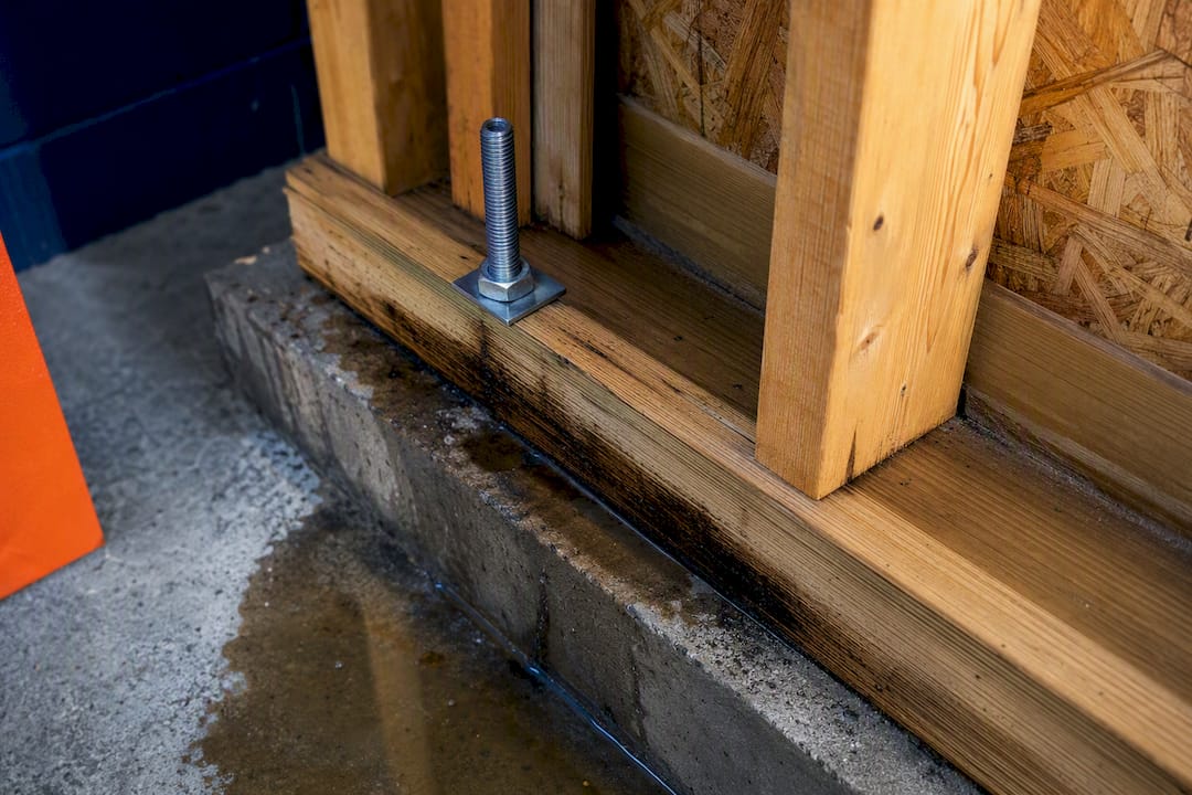
Corrosion at anchor bolts and hold-down hardware is the second durability concern, particularly in coastal environments or anywhere the wall sits near a treated foundation with dissimilar-metal contact. Galvanized or stainless hardware specifications matter more on a PSW line than a typical partition wall, since the entire wall line's uplift resistance concentrates at just two end connections rather than being spread across multiple hold-downs.
Periodic inspection of accessible anchor bolts and hold-down connections, particularly in crawl space or unfinished basement conditions where they remain visible, catches corrosion or loosening before it compromises capacity. Panel delamination from long-term moisture exposure inside a wall cavity is harder to catch without invasive inspection, which is one more reason vapor barrier detailing and flashing at window and door openings deserve the same scrutiny as the structural calculation itself.
Research Trends in Perforated Shear Wall Design
Refinements to the Co table and the underlying Sugiyama-based empirical model continue as more full-scale test data on walls with varied opening configurations becomes available. Much of the current interest centers on reducing the conservatism built into the uniform uplift assumption, since real segment-by-segment shear distribution along a perforated wall line is rarely as uniform as the vmax approach assumes.
Engineered wood products, cross-laminated timber panels and mass plywood panels among them, are pushing PSW-style thinking into taller, multi-story applications beyond the traditional light-frame residential scope, though the 20-foot height limit still governs prescriptive applications under current code language. Software-driven interpolation and automated collector checks are also narrowing the gap between hand-calculation conservatism and the wall's actual tested performance, letting engineers document a defensible design without over-specifying hardware that the wall doesn't structurally need.
Practical Trade-Offs When Specifying Perforated Shear Walls
Perforated shear wall design earns its place when openings distribute across a wall line with solid end restraint. It saves on anchors and labor. Reach for segmented or FTAO design instead when elevations aren't uniform, walls exceed 20 feet, or one segment alone must carry disproportionate capacity.
— Evalin
Automate Your Perforated Shear Wall Calculations
Running Co interpolation, vmax, and chord forces by hand for every wall line on a two-story project eats hours you don't have during permit crunch time. ShearWise Pro automates that entire perforated shear wall workflow, from full-height segment identification through hold-down sizing, and outputs a clean PDF report built for plan review.

The free trial includes three watermarked reports, enough to run a real project through the full PSW method and see how the interpolated Co and anchorage outputs compare to your own hand calculations. Residential wood-frame designers working on 1- or 2-story structures get the most immediate value, since that's exactly the scope the platform is built around. Sign up to try ShearWise Pro on your next wall line and check the output against your own numbers before your next submittal deadline.