

The accepted California method for shear wall overturning resistance is an equilibrium check: compute the overturning moment (Mu) from lateral loads about the wall toe, compute the resisting moment (Mr) from credited dead loads plus anchorage capacity, and verify Mr ≥ Mu under every governing load combination. This procedure applies to light-frame wood shear walls under ASCE 7, CBC/IBC, and SDPWS, and it is the workflow California plan checkers expect to see documented on your structural notes.
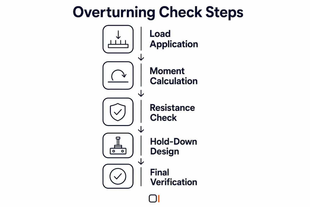
Before running numbers, confirm these steps:
- Identify lateral demand. Determine seismic or wind base shear and distribute to each shear wall line using a force takedown.
- Select dead loads to credit. Include floor/roof self-weight and wall self-weight per ASCE 7 Chapter 2 reduction rules; reduce by a small amount per level for wind checks.
- Compute lever arms. Measure from the load centroid to the wall toe (compression end).
- Size hold-downs and anchors. Match required uplift to allowable capacity, adjusted for cracked concrete and seismic reductions.
- Document on plans. List hold-down model, design uplift in lbs, anchor type, embedment depth, and inspection requirements.
Primary code callouts for plan sheets: ASCE 7 Chapter 2 (load combinations and dead-load reductions), CBC/IBC Chapter 16 (load combinations), SDPWS Section 4.3.6.4.2 (uplift anchorage), CRC R602.10 (prescriptive bracing), and California Administrative Code overturning language via UpCodes.
Table of Contents
- Which codes govern shear wall overturning checks in California?
- What causes overturning and what resists it?
- How do you calculate shear wall overturning step by step?
- How do you size hold-downs and check concrete anchors?
- Which load combinations apply, and when do you discount dead loads?
- What are the most common errors in California overturning practice?
- How ShearWise Pro implements the overturning method
- Key Takeaways
- The case for conservative defaults in California practice
- ShearWise Pro: permit-ready overturning reports without the manual setup
- Useful sources and references for permit submittals
Which codes govern shear wall overturning checks in California?
| Standard | Key Sections | What It Covers |
|---|---|---|
| ASCE 7 | Chapter 2, Chapter 12 | Load combinations, dead-load reduction rules, seismic demands |
| IBC / CBC | Chapter 16 | Adopted load combinations; California amendments |
| SDPWS | §4.3.6.4.2, §4.3.6.1.2 | Uplift anchorage trigger, dead-load stabilizing moment |
| CRC R602.10 | R602.10.1, R602.10.3(4) | Prescriptive braced wall lines, panel lengths, hold-down schedules |
| California Administrative Code | Overturning provisions | Resistance ≥ 0.75 × base moment for certain critical-facility checks |
CRC R602.10 requires braced wall lines spaced no more than 35 feet in Seismic Design Category D, with panel lengths and hold-down schedules spelled out in code tables. SDPWS Section 4.3.6.4.2 is the clause that explicitly triggers the hold-down requirement: when the dead-load stabilizing moment is insufficient to prevent uplift, an anchoring device is required at each shear wall end.
California Administrative Code language, accessible through UpCodes, states that overturning resistance may be taken as the righting moment about the footing edge or the wall's flexural capacity, whichever is less, and that calculated resistance must exceed 0.75 times the base moment for certain evaluation procedures. This matters for hospital and essential-facility projects where the acceptance threshold is explicit.
Jurisdictional amendments matter. The City of Los Angeles requires L.A. Research Reports (L.A.R.R.) for connector allowable values and applies more restrictive seismic reductions to anchor capacities than the base IBC. Check LADBS bulletins before finalizing any anchor selection on an L.A. project.
What causes overturning and what resists it?
Overturning is the moment a lateral load creates about the toe (compression end) of the shear wall. Wind or seismic force applied at the diaphragm level multiplied by the wall height produces that moment. Resisting it are gravity dead loads, structural flexural capacity, and, where applicable, friction on piling or earth weight over below-grade foundations.

Dead loads applied to shear walls reduce uplift at the tension end and are a widely accepted practice for light-frame wood design. The load can be modeled as a uniform distributed load along the wall length or simplified to a concentrated load at the centroid of the tributary area. For most residential walls, the concentrated-load simplification is standard practice and matches the approach used in Design of Wood Structures (Breyer et al.) and the SEAOC Structural/Seismic Design Manual.
Lever arm selection is where errors creep in. The lever arm for the dead-load resisting moment is measured from the centroid of the dead load to the toe of the wall, not to the hold-down anchor. For a uniform dead load over the full wall length L, the centroid is at the midpoint of the wall, so Mr(dead) equals the dead load multiplied by the lever arm to that midpoint. For a concentrated dead load at a specific column or post, use the actual horizontal distance to the toe.
Rigid-body analysis works well for most short, full-height shear wall segments. It becomes less reliable for long walls with low aspect ratios, perforated shear walls, or walls with significant openings. For those cases, full-height segment design or a beam-on-elastic-foundation approach is more appropriate, though the latter exceeds standard practice for most residential projects.
How do you calculate shear wall overturning step by step?
The equilibrium check follows a direct sequence. Compute Mu from lateral loads, compute Mr from dead loads and anchorage, then verify the ratio.
Key equations:
- Mu = F_lateral × h (lateral force × wall height to diaphragm)
- Mr(dead) = W_DL × (L/2) (uniform dead load × half wall length)
- Mr(total) = Mr(dead) + Mr(flexural or footing righting moment)
- Required: Mr(total) ≥ Mu
Worked numeric example
Given geometry and loads:
- Wall length: L = 8 ft
- Wall height: h = 10 ft
- Lateral shear at top (seismic, ASD level): V = 2,400 lb
- Dead load tributary to wall (roof + wall self-weight): W_DL = 3,200 lb (uniform over 8 ft)
Step 1 — Compute overturning moment about toe:
Mu = V × h = 2,400 lb × 10 ft = 24,000 ft-lb
Step 2 — Compute resisting moment from dead load:
Mr(dead) = W_DL × (L/2) = 3,200 lb × 4 ft = 12,800 ft-lb
Step 3 — Compute required hold-down uplift force:
Net uplift demand at tension end = (Mu − Mr(dead)) / L = (24,000 − 12,800) / 8 = 1,400 lb (ASD)
Step 4 — Select hold-down and verify:
Select a hold-down with allowable uplift ≥ 1,400 lb (ASD), adjusted for load duration factor C_D = 1.6 for seismic. Verify anchor embedment and edge distances per manufacturer tables.
Step 5 — Check load combinations:
Run the same check under wind load combinations with dead load reduced by 2–3 psf per level to avoid inflating Mr for wind cases.
Load combination reference table
| Load Case | ASCE 7 / IBC Combination | Dead-Load Factor | Notes |
|---|---|---|---|
| Seismic (ASD) | 0.6D + 0.7E | 0.6 | Reduces dead-load credit |
| Seismic (LRFD) | 0.6D + 0.7E | 0.6 | Use for LRFD hold-down sizing |
| Wind (ASD) | 0.6D + 0.6W | 0.6 | Conservative; reduce DL further if uncertain |
| Wind (LRFD) | 0.6D + 0.6W | 0.6 | Standard LRFD wind uplift check |
The California Administrative Code also allows resistance to be taken as the righting moment about the footing edge or the wall's flexural capacity, whichever governs, for certain evaluation procedures.
How do you size hold-downs and check concrete anchors?
After confirming Mr ≥ Mu, the next step is sizing hold-downs and anchors so that allowable uplift capacity meets the required uplift under adjusted load combinations. Combined shear and axial demands must also be checked where both act simultaneously.
Hold-down and anchor checklist:
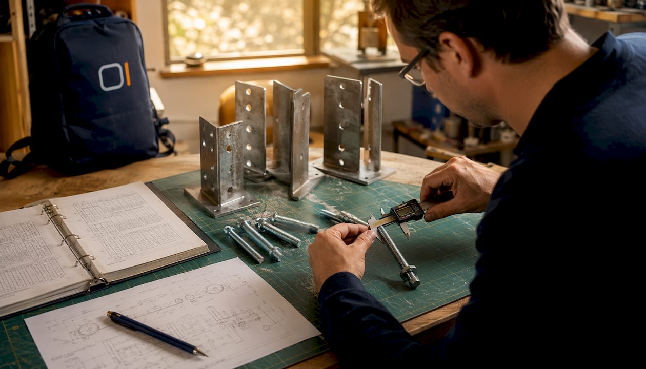
- Select hold-down model. Use Simpson Strong-Tie SBSD or equivalent manufacturer tables to identify a hold-down with allowable uplift ≥ required demand (ASD or LRFD as applicable).
- Confirm anchor embedment. Verify minimum embedment depth per manufacturer specifications and ACI 318 Chapter 17 for post-installed anchors.
- Check edge and spacing limits. Minimum edge distance and anchor spacing affect capacity; confirm against the anchor's ICC-ES evaluation report.
- Apply cracked-concrete modifier. For concrete foundations, use cracked-concrete capacity values unless the foundation is demonstrably uncracked. This often reduces allowable capacity by 20–30%.
- Apply seismic reduction factors. For seismic applications, anchor capacities are further reduced per ACI 318 §17.2.3 or the applicable ICC-ES report.
- Check transfer strap forces. Where straps transfer shear or tension across floor framing, verify strap capacity and eccentricity effects at the connection.
- Verify combined shear and uplift. Where the anchor carries both shear and tension simultaneously, apply the interaction equation from the manufacturer's table or ACI 318.
Plan documentation requirements: List the hold-down model number, design uplift in pounds, anchor type, embedment depth, required washer or bearing plate size, and concrete strength assumed. Call out field inspection points, including pre-pour anchor placement and post-installation torque testing for post-installed anchors.
Pro Tip: For projects in Los Angeles, always reference the applicable L.A.R.R. values for connector allowable loads. After Northridge, LADBS adopted more restrictive anchorage criteria, and using standard ICC-ES values without the L.A.R.R. reduction is a common cause of plan-check corrections. When in doubt, increase embedment or select the next larger anchor rather than arguing capacity at plan check.
For anchor bolt layout specifics, the shear wall anchor bolt layout guide covers spacing, edge distances, and embedment requirements in detail.
Which load combinations apply, and when do you discount dead loads?
Use the governing load combinations from ASCE 7 and CBC/IBC for all overturning checks. The critical rule: dead-load credit is not free. ASCE 7 Chapter 2 requires a 0.6 factor on dead load in the ASD overturning combination (0.6D + 0.6W or 0.6D + 0.7E), which already reduces the resisting moment. Beyond that code minimum, conservative practice calls for an additional reduction of 2–3 psf per level when evaluating wind overturning.
| Scenario | When to Reduce Dead-Load Credit | Practical Action |
|---|---|---|
| Wind overturning check | Always; DL often overestimated | Subtract 2–3 psf per level from assumed dead load |
| Seismic overturning check | Apply 0.6D factor per ASCE 7 | Model dead loads rationally; no additional reduction typically needed |
| Multi-story tension accumulation | When stacked shear walls share tension | Verify cumulative uplift at each level; do not assume DL offsets all uplift |
| Conservative design | Uncertain dead-load values | Omit dead-load credit entirely; size hold-downs for full Mu |
WoodWorks guidance is direct on this point: inflated dead loads produce conservative seismic forces and conservative gravity member design, but they exaggerate resisting moments when evaluating wind overturning. The result is under-designed tension members in multi-story walls. Reducing assumed dead load by 2–3 psf per level for wind checks is a practical safeguard against that outcome.
Omitting dead-load credit entirely is the most conservative approach and is appropriate when dead-load values are uncertain or when the project is in a high-wind zone where the margin matters. The trade-off is larger hold-downs, but that is a known and manageable cost.
What are the most common errors in California overturning practice?
Frequent pitfalls to avoid:
- Missing braced wall line labels. Plan checkers routinely flag submittals that lack braced wall line markings, bracing method tags, and minimum panel length callouts per CRC R602.10.
- Vague hold-down notes. Generic notes like "see structural engineer for hold-downs" are rejected. California plan checkers require explicit hold-down model numbers, design uplift in pounds, and locations on the framing plan.
- Inflating dead-load credit for wind checks. Using the same (higher) dead-load values for both seismic and wind overturning checks leads to under-designed tension members in multi-story walls.
- Ignoring L.A. anchor value reductions. Applying standard ICC-ES allowable values without checking L.A.R.R. requirements is a consistent source of plan-check corrections on Los Angeles projects.
- Omitting lever arm and load breakdown. Calculations that state a resisting moment without showing the dead-load value, tributary area, and lever arm give plan checkers no way to verify the result.
- Misapplying CRC R602.10 prescriptive tables. The prescriptive path is not applicable for irregular footprints, stories over prescriptive height limits, proprietary engineered shear walls, or unusual load paths.
When a stamped engineered design is required: Irregular floor plans, building heights exceeding CRC R602.10 prescriptive limits, proprietary engineered shear wall systems, and any condition outside the explicit scope of R602.10 all require a licensed engineer's stamped calculations. The prescriptive vs. engineered design comparison covers the decision criteria in detail.
Best practices: List every hold-down on the structural notes with model and design load. Include a one-page overturning summary table in the calculation package showing Mu, Mr, and net uplift for each wall line. Attach manufacturer technical bulletins or L.A.R.R. references for any anchor value used in design.
How ShearWise Pro implements the overturning method
ShearWise Pro encodes the same equilibrium and dead-load credit workflow described above and outputs calculation checks, hold-down schedules, anchor details, and PDF reports formatted for permit submission. The platform is built for 1-story and 2-story wood-framed buildings, which covers the majority of California residential and light commercial projects where this method applies.
Feature snapshot:
- Wall line organization with full-height segment tracking and opening inputs
- Dead-load modeling options: distributed or concentrated load at centroid
- Automatic load combination checks (ASD and LRFD) for seismic and wind
- Hold-down force summary with model and design load per wall end
- Anchor embedment and plate requirement notes
- Exportable PDF calculation pages with Mu vs. Mr summary, hold-down schedule, and code citations
Example report items for permit submittal: overturning summary table (Mu, Mr, net uplift per wall line), hold-down schedule with model numbers and design loads in pounds, anchor embedment and washer/plate requirements, and a notes section citing ASCE 7, SDPWS, and CRC sections used.
Results produced by ShearWise Pro must be independently reviewed and stamped by the licensed engineer of record before permit submission. The tool accelerates the calculation workflow; engineering judgment and professional responsibility remain with the engineer.
Key Takeaways
The California shear wall overturning method requires an equilibrium check (Mr ≥ Mu) under ASCE 7 load combinations, with dead-load credit reduced for wind checks and hold-downs sized to the net uplift demand.
| Point | Details |
|---|---|
| Core equilibrium check | Verify Mr ≥ Mu under all governing load combinations before sizing hold-downs. |
| Dead-load credit limits | Reduce assumed dead load by 2–3 psf per level for wind overturning to avoid under-designed tension members. |
| L.A. anchor reductions | Always check L.A.R.R. values for Los Angeles projects; standard ICC-ES values may not satisfy LADBS requirements. |
| Plan documentation | List hold-down model, design uplift in lbs, anchor type, embedment, and inspection callouts on the framing plan. |
| ShearWise Pro | Organizes wall lines, dead-load inputs, load combinations, and hold-down schedules into permit-ready PDF reports for 1–2 story wood buildings. |
The case for conservative defaults in California practice
The debate over how much dead load to credit is real, and the answer depends on which load case you are checking. For seismic, modeling dead loads rationally is defensible and widely accepted. For wind, the calculus shifts. Dead loads are often estimated on the high side during early design, and using those inflated values to offset wind overturning can quietly under-size tension members in multi-story walls. The fix is simple: subtract 2–3 psf per level from your assumed dead load when running wind overturning checks. That small reduction catches the cases where your dead-load estimate was optimistic.
On documentation, the single most effective change most engineers can make is adopting a standard one-page overturning summary template for every project. The template should include: project name and governing codes cited, a Mu/Mr summary table for each wall line, the hold-down schedule with model numbers and design loads, anchor type and embedment, and a verification/inspection note. Plan checkers in California see hundreds of submittals. A clean, consistent summary page reduces back-and-forth and signals that the calculations are complete.
For projects in Los Angeles or other jurisdictions with local bulletins, cross-reference LADBS L.A.R.R. values before finalizing any anchor selection. The post-Northridge reductions are not optional, and discovering them at plan check costs more time than checking them upfront.
ShearWise Pro: permit-ready overturning reports without the manual setup
Pulling together a complete overturning package, wall line by wall line, hold-down by hold-down, is where residential projects lose the most calculation time. ShearWise Pro packages the entire workflow: dead-load modeling options, automatic Mu vs. Mr checks under ASD and LRFD combinations, hold-down force schedules, anchor embedment notes, and clean PDF reports formatted for California plan check. You enter the geometry, loads, and wall lines; the platform organizes the output into a permit-ready calculation package.

A trial gives you a working example report showing the overturning summary table, hold-down schedule with model numbers and design loads, and anchor details with code citations. For firms integrating calculation tools into their standard workflow, the engineering firm software integration checklist covers what to evaluate before adopting a new platform.
The licensed engineer of record must review and stamp all calculations before submission. ShearWise Pro accelerates the process; the engineering judgment stays with you. Start your trial at shearwisepro.com.
Useful sources and references for permit submittals
| Source | What to Cite or Attach |
|---|---|
| WoodWorks — Using Dead Loads to Resist Shear Wall Overturning | Dead-load modeling options, SDPWS §4.3.6.4.2 reference, wind reduction guidance |
| SDPWS | §4.3.6.4.2 uplift anchorage trigger; nominal shear capacities for wood structural panels |
| CRC R602.10 — CrossBeam | Prescriptive braced wall line requirements, panel lengths, hold-down schedule tables |
| UpCodes — California Administrative Code Overturning | Overturning resistance language; 0.75 × base moment acceptance criterion |
| Simpson Strong-Tie SBSD | Hold-down and anchor allowable values, transfer methods, installation details |
| Simpson Strong-Tie L.A.R.R. Technical Bulletin | City of Los Angeles reduced allowable values; L.A.R.R. publication references |
Recommended attachment order for permit packages: (1) one-page code citation list naming ASCE 7, CBC/IBC, SDPWS, and CRC sections used; (2) overturning summary table with Mu, Mr, and net uplift per wall line; (3) hold-down schedule; (4) anchor embedment and plate details; (5) manufacturer technical bulletins or L.A.R.R. excerpts for any non-standard anchor value. This order matches what California plan checkers look for first and reduces the likelihood of a correction notice requesting additional documentation.