
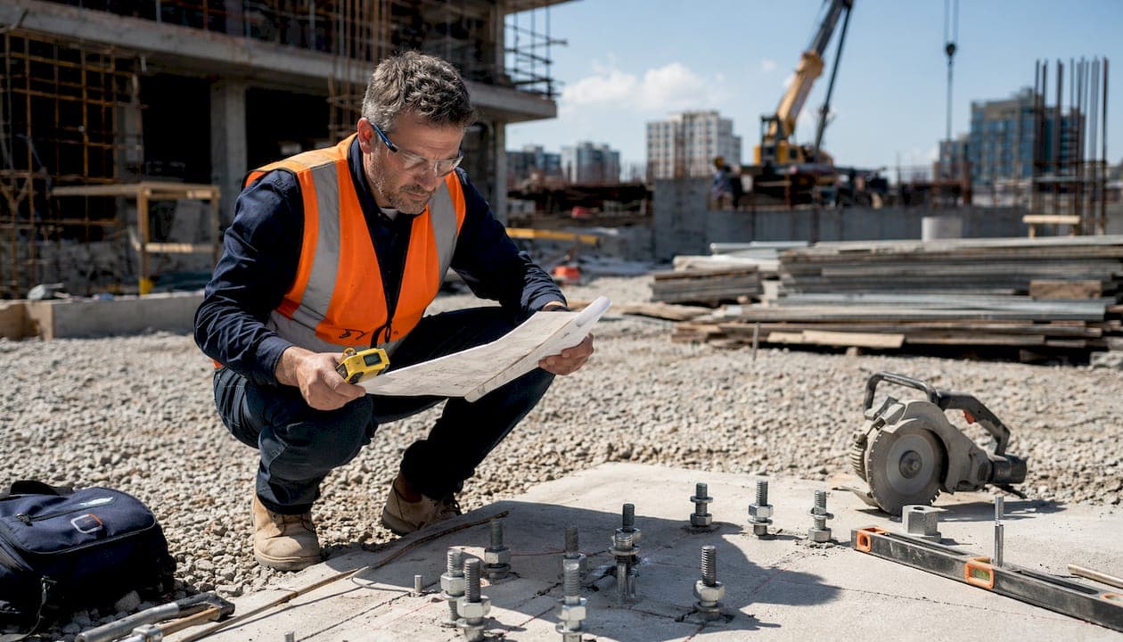
Shear wall anchor bolt layout is the precise arrangement of anchor bolts and hold-down hardware that transfers lateral loads from wood framing into the foundation. Getting this layout right determines whether your shear wall system performs under wind or seismic forces. IRC R403.1.6 sets the minimum prescriptive requirements for bolt diameter, spacing, embedment, and washer size. Anchor bolts resist sliding forces along the sill plate, while hold-down hardware at panel ends resists overturning. Both must be coordinated before the concrete pour.
What are the IRC requirements for shear wall anchor bolt layout?
IRC R403.1.6 mandates minimum 1/2-inch diameter anchor bolts embedded at least 7 inches into concrete or masonry, spaced no more than 6 feet on center. At least two bolts are required per sill plate section. Each bolt must fall within 12 inches of every sill plate end to prevent the plate from lifting or sliding at its most vulnerable points.
A 3-inch square or round plate washer is required under each nut. Without it, the nut bearing area is too small and crushes the sill plate under lateral stress. This single detail is one of the most commonly missed items during foundation inspection.
Enhanced requirements for high-wind and seismic zones
Prescriptive minimums are not always enough. In high-wind or seismic zones, engineered designs may call for 5/8-inch diameter bolts, tighter spacing, and supplemental hardware beyond what IRC prescribes. Wind Exposure Categories C and D, along with Seismic Design Categories C through F, trigger these elevated requirements. When the project falls into these categories, defer to the structural engineer's design rather than the prescriptive table.
The table below summarizes the IRC prescriptive minimums alongside typical engineered upgrades:
| Parameter | IRC Prescriptive Minimum | Engineered High-Load Upgrade |
|---|---|---|
| Bolt diameter | 1/2 inch | 5/8 inch or larger |
| Embedment depth | 7 inches | 10 inches or per design |
| Maximum spacing | 6 feet on center | 4 feet or less |
| Plate washer size | 3-inch square or round | 3-inch or per engineer |
| End bolt distance | Within 12 inches of plate end | Within 6 inches per design |
How to coordinate anchor bolt placement with hold-down hardware
Anchor bolts only counter sliding; hold-down hardware bears the overturning forces at braced wall ends. Treating them as interchangeable is a critical error. A shear wall panel without properly installed hold-downs will rotate off the foundation under lateral load, even when every anchor bolt is perfectly placed.
Coordination starts with the engineer's hold-down schedule and the relevant ICC-ES evaluation reports for each hardware product. These documents specify the exact rod diameter, embedment depth, and installation torque for each hold-down type. Field substitutions without engineering approval void the design.
Follow these steps to coordinate bolt placement with framing before the pour:
- Mark all hold-down rod locations on the foundation plan, noting which studs they attach to. Hold-down rods typically land at king studs adjacent to shear wall boundary elements.
- Lay out anchor bolt positions at the required spacing, keeping each bolt clear of stud locations, plate joints, and hold-down rods. Bolts conflicting with framing elements cause installation delays and may render the bolt unusable.
- Check door and window openings. Bolts placed under or adjacent to rough openings often conflict with jack studs and trimmer configurations. Adjust spacing to keep bolts within full-height wall segments only.
- Confirm end bolt placement. Each sill plate section needs a bolt within 12 inches of both ends. Mark these positions first, then fill in intermediate bolts at the required spacing.
- Verify material specifications. Hot-dip galvanized (G-185) or stainless steel fasteners are required when anchor bolts contact pressure-treated sill plates. Standard zinc-plated hardware corrodes rapidly in contact with modern wood treatment chemicals.
Pro Tip: Use a bolt template or jig cut from plywood to set bolt positions before the pour. Mark stud locations on the template so you can visually confirm that no bolt lands under a stud pack or hold-down rod location.
Step-by-step process for laying out and installing anchor bolts
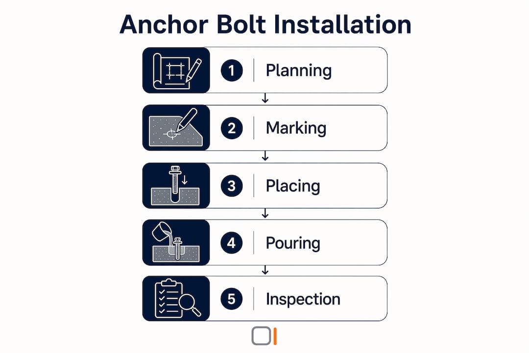
Proper installation begins well before concrete is placed. Coordination before the pour is the single biggest factor in avoiding field rework and failed inspections.
Pre-pour planning
Transfer the framing layout onto the foundation plan. Mark every wall line, door opening, hold-down location, and stud spacing. Identify each sill plate section and calculate the required number of bolts per section. Confirm that end bolts fall within 12 inches of each plate end.
Setting bolts during the pour
- Place bolts using a template or jig to maintain consistent spacing and alignment.
- Verify each bolt is plumb before concrete sets. Angled bolts create bearing problems when the nut is tightened.
- Check embedment depth with a tape measure before the concrete stiffens. Minimum 7 inches of embedment is non-negotiable.
- Confirm the correct projection above the slab. The bolt must extend far enough to accommodate the sill plate thickness, plate washer, and nut with full thread engagement.
Post-pour installation
- Place the sill plate over the bolts and drill holes at marked locations.
- Slide the 3-inch plate washer over each bolt before threading the nut.
- Tighten nuts to snug-tight, meaning the washer is fully seated against the plate with no rocking. Do not over-torque, which can split the sill plate.
- Install hold-down hardware per the engineer's schedule and ICC-ES instructions. Torque hold-down nuts to the specified value.
Inspection priorities
Inspectors check bolt diameter, spacing, embedment, projection, washer size, and nut installation. The most common field failures are missing plate washers, bolts placed too far from sill plate ends, and bolts set at an angle during the pour.
What are the most common mistakes in anchor bolt installation?
Most anchor bolt failures trace back to layout errors made before the pour, not installation errors after it. Fixing a misplaced bolt in hardened concrete is expensive and time-consuming. Prevention is the only practical strategy.
- Spacing exceeds 6 feet. This is the most frequent code violation. Measure every bay and confirm compliance before the pour, not during framing.
- Missing end bolts. Forgetting to place a bolt within 12 inches of a sill plate end leaves the most vulnerable section of the plate unanchored.
- Bolts under studs or plate joints. A bolt directly under a stud cannot be drilled through without cutting the stud. Bolts placed at plate joints split the plate when tightened.
- Wrong or missing washers. Standard flat washers do not meet the 3-inch minimum bearing area requirement. Using them fails inspection and reduces load transfer capacity.
- Assuming anchor bolts resist overturning. Missing hold-downs cause shear wall rotation off the foundation even when anchor bolts are correctly installed. Anchor bolts and hold-downs serve different structural functions.
- Incorrect fastener material. Standard zinc-plated bolts corrode when in contact with ACQ or CA pressure-treated lumber. G-185 galvanized or stainless steel is the correct specification.
Pro Tip: Before the pour, walk the foundation with the framing plan in hand and physically mark each bolt location with a lumber crayon. Cross-check against hold-down rod locations and door openings. This five-minute check prevents hours of remediation.
How does anchor bolt layout affect lateral load paths?
Anchor bolts are one link in a continuous lateral load path that runs from the roof diaphragm through the shear wall sheathing, into the sill plate, and down into the foundation. A weak or missing connection at any point breaks the path. The system performs only as well as its weakest detail.
Lateral design is primarily a connection and detailing problem. The system is only as strong as its weakest link, requiring strict adherence to manufacturer installation instructions.
Research confirms that increasing fastener spacing reduces wall racking stiffness by 31% to 42%. That stiffness reduction applies not just to sheathing nails but to any fastener in the load path, including anchor bolts. A bolt spaced too far from a sill plate end creates a local flexibility that allows the plate to rock before load transfers to the foundation.
Hold-down hardware at shear wall boundary elements works alongside anchor bolts to complete the load path. Anchor bolts prevent the sill plate from sliding horizontally. Hold-downs prevent the wall panel from rotating about its base. Both forces act simultaneously under lateral loading, so both connections must be present and correctly installed.
The table below shows how connection failures affect load path performance:
| Connection failure | Structural effect | Code reference |
|---|---|---|
| Missing anchor bolt near plate end | Plate slides or lifts at end | IRC R403.1.6 |
| Bolt spacing exceeds 6 feet | Plate slides between bolts | IRC R403.1.6 |
| Missing hold-down at panel end | Panel rotates off foundation | Engineer's schedule |
| Undersized plate washer | Nut crushes sill plate | IRC R403.1.6 |
| Wrong fastener material | Corrosion reduces capacity | G-185 / SS specification |
Coordination with the shear wall nailing schedule is equally critical. A correctly anchored sill plate connected to under-nailed sheathing still fails. Every element in the load path must meet its design requirement.
Key Takeaways
A correct shear wall anchor bolt layout requires IRC-compliant bolt sizing, spacing, and embedment, combined with properly installed hold-down hardware and corrosion-resistant fasteners coordinated before the concrete pour.
| Point | Details |
|---|---|
| IRC R403.1.6 minimums | Use 1/2-inch bolts at 6-foot max spacing, 7-inch embedment, within 12 inches of plate ends. |
| Plate washers are required | Install 3-inch square or round plate washers under every nut to prevent sill plate crushing. |
| Anchor bolts vs. hold-downs | Anchor bolts resist sliding; hold-downs resist overturning. Both must be installed per design. |
| Coordinate before the pour | Mark bolt and hold-down locations on the foundation plan before concrete is placed to avoid framing conflicts. |
| Use corrosion-resistant fasteners | Specify G-185 hot-dip galvanized or stainless steel hardware with pressure-treated sill plates. |
The detail that separates good shear wall design from field failures
After years of reviewing shear wall designs and walking job sites, the pattern is consistent. Most anchor bolt problems are not engineering failures. They are coordination failures. The engineer specifies the correct layout. The contractor pours the foundation before the framing plan is fully coordinated. Bolts end up under studs, too close to hold-down rods, or missing entirely from sill plate ends.
The fix is not more inspection after the fact. The fix is a pre-pour coordination meeting where the framing plan, hold-down schedule, and foundation plan are reviewed together. That meeting takes 30 minutes. Remediation after a failed inspection takes days.
I have also seen projects where every anchor bolt was perfectly placed, but the hold-downs were installed without the required ICC-ES hardware. The wall looked correct from the outside. Under lateral load, it would have rotated off the foundation. Anchor bolts and hold-downs are not interchangeable, and neither one is optional.
The other issue I see repeatedly is fastener material. Contractors specify standard zinc-plated bolts because they are cheaper and easier to source. Modern pressure-treated lumber contains copper compounds that accelerate corrosion of standard zinc coatings. Within a few years, the anchorage capacity drops significantly. G-185 galvanized or stainless steel is not a premium upgrade. It is the correct specification for this application.
Use shear wall design tools that track hold-down forces, wall line assignments, and bolt layout requirements together. Keeping these details in separate spreadsheets or hand-marked plans is where coordination errors start.
— Evalin
ShearWise Pro: organized shear wall design from layout to report
Coordinating anchor bolt placement, hold-down schedules, and lateral load calculations across multiple wall lines is where projects get complicated. ShearWise Pro organizes all of it in one place.

The shear wall calculator handles wall lines, full-height segments, hold-down forces, transfer straps, and story drift checks for 1-story and 2-story wood-framed buildings. You can generate clean PDF reports that document your anchor bolt layout decisions alongside hold-down hardware schedules, ready for plan review and inspection coordination. ShearWise Pro keeps your design organized and your documentation complete, so nothing gets missed between the engineer's desk and the foundation pour. Visit ShearWise Pro to see how it fits your workflow.
FAQ
What is the minimum anchor bolt size required by IRC?
IRC R403.1.6 requires a minimum 1/2-inch diameter anchor bolt embedded at least 7 inches into concrete or masonry. High-wind and seismic zones may require 5/8-inch diameter bolts per the engineered design.
How far apart should anchor bolts be spaced in a shear wall?
IRC R403.1.6 sets a maximum spacing of 6 feet on center, with at least one bolt within 12 inches of each sill plate end. Engineered shear wall designs often require tighter spacing.
Do anchor bolts replace hold-down hardware?
No. Anchor bolts resist horizontal sliding of the sill plate, while hold-down hardware resists overturning forces at shear wall panel ends. Both are required and serve different structural functions.
What type of washer is required under anchor bolt nuts?
A minimum 3-inch square or 3-inch diameter round plate washer is required under each nut to distribute bearing load and prevent crushing of the sill plate.
What fastener material is correct for pressure-treated sill plates?
Hot-dip galvanized (G-185) or stainless steel anchor bolts and hardware are required when in contact with pressure-treated lumber. Standard zinc-plated fasteners corrode rapidly with modern wood treatment chemicals.