
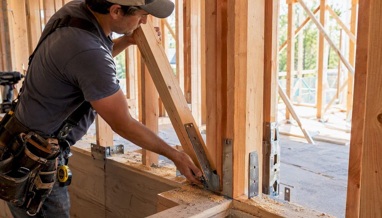
In residential wood framing, a tapered shear wall refers to a lateral-resisting shear wall whose effective shear length or panel layout changes with height due to openings, varying pier widths, or asymmetric geometry — not a soil-retaining structure. For most tapered configurations, use Force Transfer Around Openings (FTAO) or the rational Diekmann method. Both approaches account for actual load paths through straps and blocking, produce smaller hold-downs than conservative segmented assumptions, and generate the calculation pages permit reviewers expect.
Before running any numbers, confirm three things: wall geometry and opening dimensions from the plan set, diaphragm tributary loads from the roof and floor framing, and whether the project's SDC, wind speed, or aspect ratios push it outside IRC prescriptive limits.
- Gather wall geometry: pier widths (Li), opening heights and widths, and total wall length (L)
- Confirm sheathing type, thickness, and percent full-height sheathing
- Collect story weights, Sds/Sd1, ASCE 7 exposure category, and SDC
- Identify diaphragm tributary widths for each shear wall line
- Check whether any pier aspect ratio exceeds 3.5:1 (SDPWS limit for perforated walls)
Table of Contents
- When does a tapered shear wall require engineered design?
- Which analysis method fits your tapered wall geometry?
- Step-by-step calculation workflow for tapered shear walls
- What to show on drawings for tapered shear walls
- Common mistakes in tapered shear wall design
- How ShearWise Pro fits the tapered shear wall workflow
- Validation and trusted references for FTAO and rational methods
- Key takeaways
- Where conservatism earns its place in tapered shear wall design
- ShearWise Pro: from tapered wall inputs to permit-ready PDF
When does a tapered shear wall require engineered design?
Prescriptive IRC braced-wall rules work for straightforward geometry. Once any of the following conditions appear, engineered design is required:
- A full-height pier's aspect ratio exceeds the WFCM/SDPWS limit (2:1 for segmented, 3.5:1 for perforated)
- Openings or tapering reduce full-height sheathing below the minimum requirement for perforated wall tables
- Wind speed, SDC, or roof load falls outside the prescriptive table ranges in the WFCM Workbook
- A shear wall line is offset more than a few feet from the line above or below
- Multi-story cumulative hold-down forces exceed what prescriptive anchor schedules cover
- The designer wants to count sheathing above and below openings toward wall capacity (FTAO territory)
Run this check in under two minutes: look at the tallest pier, compute h/b, compare to the applicable limit, then check the opening percentage. If either fails, you are in engineered territory.
Pro Tip: Before opening a spreadsheet, confirm the roof diaphragm tributary width and floor dead load on the plan. Missing these two inputs causes more hold-down undersizing errors than any calculation mistake.
Which analysis method fits your tapered wall geometry?
Four methods are accepted under WFCM/SDPWS. Choosing the right one up front saves significant rework.
| Method | When to use | Key advantage | Primary checks |
|---|---|---|---|
| Segmented (SSW) | Simple geometry, piers within aspect ratio limits | Straightforward; no strap design required | Pier capacity, hold-downs at each pier end |
| Perforated (PSW) | Continuous sheathing, moderate openings | Fewer hold-downs; Co factor reduces required length | Co factor, max opening ratio, sheathing % |
| FTAO | Tapered/asymmetric openings; continuous sheathing | Counts full wall length; eliminates mid-wall hold-downs | Strap forces, corner forces, blocking |
| Rational/Diekmann | Complex multi-opening or irregular pier layouts | Most accurate strap force prediction | Free-body segmentation, all corner forces |
The FTAO technical note provides worksheet-based steps for strap and corner force calculations. For asymmetric or multi-opening walls, the Diekmann/rational method produces more precise strap force predictions, though it requires more calculation steps. West-coast offices commonly use Diekmann-based spreadsheets for exactly this reason.
Perforated walls often let you avoid hold-downs around openings entirely when continuous wood structural panel (WSP) sheathing is present, but the Co adjustment factor and maximum opening ratio must be verified. The AWC shear wall design examples show how PSW methods can reduce required wall length and hold-down sizes compared with segmented prescriptive tables. For full-height shear wall segment design, segmented analysis remains the simplest path when geometry cooperates.
Step-by-step calculation workflow for tapered shear walls
- Compute story shear. Apply ASCE 7 wind or seismic loads, then allocate to each shear wall line based on diaphragm tributary area per WFCM/SDPWS procedures.
- Determine unit shear (v, plf). Divide the wall line shear (V, lbs) by the effective wall length. For FTAO, effective length equals total wall length including sheathing above/below openings.
- Identify pier lengths (Li) and tributary opening lengths (Ti). Use plan dimensions; confirm with the shear wall segment identification checklist.
- Run FTAO steps. Compute hold-down force H = V × h/L. Solve for unit shears above (va) and below (vb) each opening. Compute total boundary forces (Oi), corner forces (Fi), local pier shears (Vi), and corner zone unit shears (vc). Size straps to resist computed corner forces.
- Apply Co factor for perforated walls. Derive Co from the sheathing percentage table in SDPWS, then adjust allowable unit shear accordingly. Verify the opening reduction factor is within table limits.
- Size hold-downs. Sum overturning from lateral shear. Add wind uplift from the roof when applicable. For a two-story building, add tension transferred from the upper-story hold-down — first-story anchors must carry cumulative loads. WFCM/SDPWS allow up to 60% of design dead load to offset overturning, which can reduce hold-down demand compared with fully conservative assumptions.
- Verify sheathing and nailing. Confirm allowable unit shear from SDPWS/UpCodes tables meets or exceeds the computed demand. Note that allowable shear values may be increased 40% for wind-only design per SDPWS.
- Assemble deliverables. Calculation pages, labeled free-body sketches, strap/hold-down schedule, nailing/sheathing schedule, and assumption list.
Pro Tip: State every conservative assumption explicitly on the calculation cover sheet — whether you applied dead-load offset, how you rounded strap values, and whether you used the allowable shear values increase for wind design per SDPWS rules. AHJs accept conservative assumptions far more readily when they are documented rather than discovered during review.
What to show on drawings for tapered shear walls
Clear plan callouts prevent RFIs and failed framing inspections. At minimum, your drawings must include:
- Wall line ID, pier lengths (Li), effective wall length, and opening dimensions labeled on the floor plan
- Analysis method called out (e.g., "FTAO per APA T555" or "Perforated per SDPWS Section 4.3")
- Strap type, location, and tabulated capacity at each opening corner
- Blocking locations at opening corners and at diaphragm-to-wall connections
- Hold-down type, location, anchor rod size, and embedment depth at each pier end
- Continuous tie path from shear wall to foundation shown in section or elevation detail
Nailing and sheathing schedule (include in the drawing set):
| Panel type | Thickness | Edge nailing | Field nailing | Special perimeter nailing |
|---|---|---|---|---|
| WSP (OSB/Plywood) | Per SDPWS table | 3" o.c. or per schedule | 12" o.c. | Per strap zone callout |
| Gypsum (if counted) | 1/2" min | Per SDPWS limits | Per SDPWS limits | Not applicable |
Note when doubled studs or larger framing members are required at sill or header locations to carry corner forces. If drift or deflection limits govern, call that out explicitly.
Common mistakes in tapered shear wall design
Errors in this work tend to cluster around a few recurring problems. Review this list before issuing any permit set:
- Ignoring stacked-story tension. First-story hold-downs in two-story buildings must include tension transferred from the story above. Sizing anchors for only the first-story shear is one of the most common shear wall design mistakes.
Pro Tip: Before finalizing the permit set, confirm anchor rod size and placement with the foundation designer. Anchor rod diameter and epoxy embedment often change when cumulative two-story hold-down forces are added — catching this before the slab is poured saves significant rework.
How ShearWise Pro fits the tapered shear wall workflow
ShearWise Pro accepts the inputs your plan set provides: wall geometry, opening dimensions, sheathing type and percentage, diaphragm tributary loads, story weights, SDC, and ASCE 7 exposure. From those inputs, the platform automates:
- Story shear allocation across wall lines
- Effective wall length and pier identification
- FTAO corner and strap force calculations
- Hold-down sizing with stacked-story summation for two-story buildings
- Nailing and sheathing schedules referenced to SDPWS
- A consolidated, permit-ready PDF with calculation pages, schedules, and plan callouts
The practical workflow is straightforward: enter plan data, review the generated calculations for any geometry flags, then export the PDF for the permit set. The shear wall calculator handles the FTAO and Diekmann steps that are most error-prone when done manually, and the output format matches what AHJs expect to see. A free trial includes three watermarked reports — enough to validate the workflow on a real project before committing to a subscription.
Validation and trusted references for FTAO and rational methods
The methods described here are not theoretical. Laboratory tests and finite-element modeling have confirmed their accuracy.
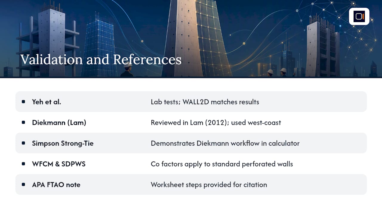
Yeh et al. conducted a series of wall tests with multiple configurations and validated strap force predictions using WALL2D finite-element modeling. WALL2D prediction errors are within a small range near test results, confirming model accuracy, confirming that rational methods give reliable strap force estimates for permit-level calculations. The Yeh et al. study remains the primary laboratory reference for FTAO and rational method validation in US residential practice.
The Diekmann method, reviewed in Lam (2012), produces reasonable strap force predictions and is widely used by west-coast engineering offices. For atypical geometries, a WALL2D check provides additional confidence. The Simpson Strong-Tie Site-Built Shearwall Designer demonstrates how these Diekmann-based steps translate into a practical calculator workflow.
WFCM and SDPWS tabulated Co factors apply to standard perforated wall configurations. When geometry falls outside those tables, FTAO or Diekmann analysis is the appropriate path, and the APA FTAO technical note provides the worksheet steps to cite in your calculations.
Key takeaways
A tapered shear wall requires FTAO or rational Diekmann analysis when openings, aspect ratios, or load cases exceed IRC prescriptive limits, and the permit report must document method, summed hold-downs, strap sizing, and code citations on a single cover-page summary table.
| Point | Details |
|---|---|
| Method selection | Choose FTAO or Diekmann when piers are asymmetric or openings exceed prescriptive limits. |
| Summed hold-downs | Always add wind uplift and stacked upper-story tension before sizing anchors. |
| Strap design | Size straps to computed corner forces from FTAO steps, not to a conservative default. |
| Plan callouts | Label pier lengths, strap locations, hold-down types, and analysis method on every permit set. |
| ShearWise Pro | Automates FTAO calculations, stacked hold-down summation, and PDF report export for permit submittals. |
Where conservatism earns its place in tapered shear wall design
The instinct to be conservative is correct, but it needs to be targeted. Rounding hold-down forces up to the next catalog size is appropriate and easy to defend. Applying dead-load offset without documenting it is the opposite: it reduces anchor demand without a visible record, and a reviewer who catches it will flag the entire submittal.
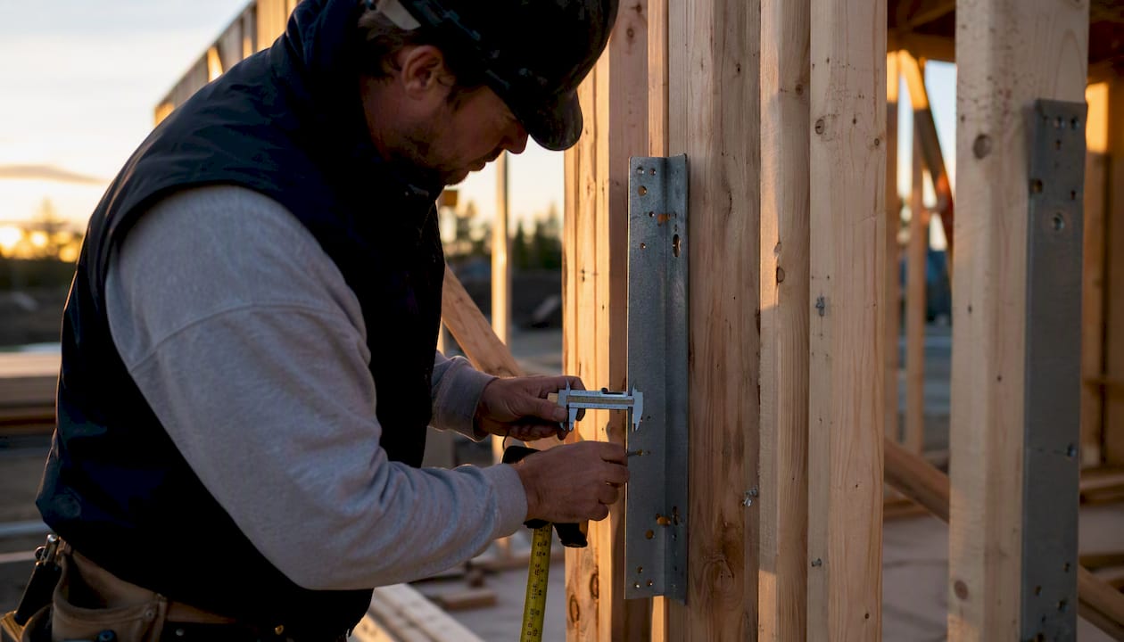
The most effective approach is to state every assumption on the cover sheet and then hold to it throughout the calculations. If you chose not to apply dead-load offset, say so. If you used the allowable shear values increase for wind design per SDPWS rules on allowable shear, cite the SDPWS section. Reviewers at most AHJs are not looking to reject submittals; they are looking for a clear load path they can follow from roof to foundation without gaps.
Coordination with framers and foundation designers before issuing the permit set prevents the most expensive errors. Anchor rod placement and diameter changes when cumulative two-story hold-down forces are added, and that change needs to reach the foundation plan before concrete is placed. Special inspection notes belong in the report only when the code edition or jurisdiction requires them; including them unnecessarily raises questions, while omitting required ones creates liability.
ShearWise Pro: from tapered wall inputs to permit-ready PDF
Tapered shear wall calculations involve more moving parts than standard segmented walls: FTAO corner forces, stacked hold-down summation, Co adjustments, and a report format that reviewers can follow without a phone call. ShearWise Pro is built specifically for this workflow in 1- and 2-story wood-framed residential projects.

Enter your wall geometry, openings, sheathing, and diaphragm loads, and ShearWise Pro generates FTAO calculations, hold-down schedules with upper-story summation, nailing and sheathing schedules, and a clean permit-ready PDF organized the way AHJs expect. The free trial includes three watermarked reports so you can verify the output against your own calculations before subscribing. Certification and tutorial resources are available for teams standardizing their permit workflow. Start your free trial at ShearWise Pro.