

A shear wall segment is defined as a full-height panel of structural sheathing that resists lateral loads between vertical boundaries created by openings or wall ends. Accurate shear wall segment identification steps determine whether a wood-framed building meets IRC 2024 lateral resistance requirements. Engineers and architects who skip or rush this process risk misaligned hold-downs, unresolved load paths, and failed permit reviews. The two recognized identification methodologies are the segmented approach and the perforated shear wall approach, each with distinct rules for hold-down placement, aspect ratio compliance, and opening treatment. Getting the classification right from the start prevents costly redesigns later.
What are braced wall lines and why do they anchor segment identification?
Braced wall lines are the structural framework on which all shear wall segment identification depends. They are continuous lines of wall, parallel to each building axis, that carry lateral loads from the diaphragm down to the foundation. Interior braced wall lines must be spaced no more than 35 feet apart according to IRC 2024. That spacing rule defines the grid within which you locate and classify every segment.
Braced wall lines run along both the exterior perimeter and through the building interior. Exterior lines form the first layer of lateral resistance. Interior lines prevent excessive diaphragm deflection between exterior walls. Without interior lines at the correct spacing, the floor or roof diaphragm spans too far and accumulates drift that code does not allow.
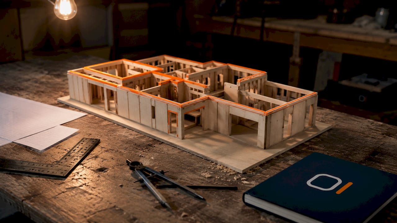
Each braced wall line must be continuous from foundation to roof. Gaps, offsets, or missing connections break the load path and invalidate the line as a qualifying element. When you establish these lines on your plans, you create the coordinate system for every subsequent segment decision.
Key attributes of a properly established braced wall line:
- Runs parallel to one of the two primary building axes
- Extends the full length of the building or terminates at a qualifying perpendicular wall
- Contains enough bracing length to satisfy IRC 2024 table requirements for the applicable wind or seismic zone
- Connects to the diaphragm above and the foundation below through specified hardware
Pro Tip: Mark each braced wall line on a separate layer in your drawing set before identifying any segments. Mixing line layout with segment markup on the same layer is one of the most common sources of identification errors during plan review.
How do you identify shear wall segments using the segmented approach?
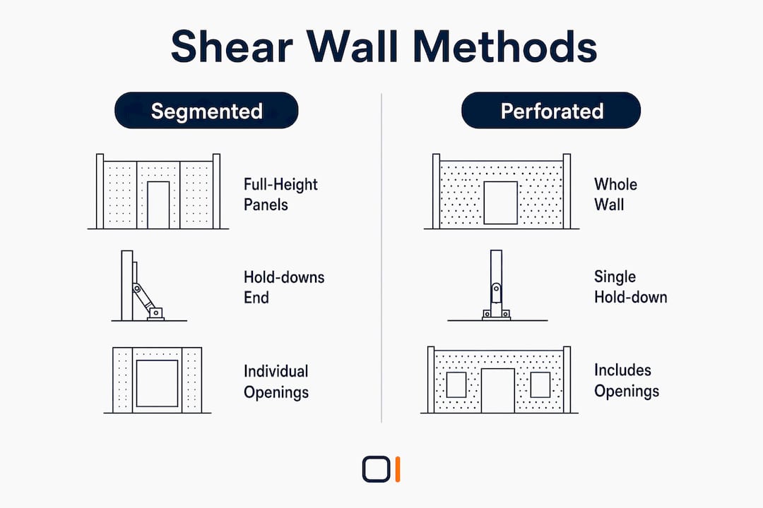
The segmented approach treats each full-height panel between openings as an independent lateral-resisting element. Each segment must conform to specified aspect ratios to qualify under code. This method gives you the highest unit shear capacity per segment but requires hold-down hardware at every segment boundary.
Follow these steps to map segments accurately on your plans:
-
Overlay your braced wall lines. Start with the line layout confirmed in the previous step. Every segment you identify must fall within a qualifying braced wall line.
-
Mark all openings. Plot every door, window, and pass-through on the wall elevation. These openings define the boundaries of each potential segment. A segment begins and ends at a full-height stud or post adjacent to an opening.
-
Measure each panel width. Record the clear width of each full-height panel. Compare that width against the panel height to calculate the height-to-width aspect ratio. Panels that exceed the maximum allowable ratio do not qualify as segments.
-
Verify minimum dimensions. IRC 2024 and engineering guidelines set minimum widths for qualifying panels. Panels narrower than the code minimum cannot carry lateral load regardless of sheathing grade.
-
Assign hold-downs at each segment end. Hold-downs must be installed at each segment end in the segmented approach to transfer lateral loads and resist overturning. Missing a hold-down at any segment boundary creates an unresolved overturning condition.
-
Document each segment in a schedule. Record segment ID, wall line, width, height, aspect ratio, sheathing specification, and hold-down model. This schedule becomes part of your permit submittal.
The table below shows how aspect ratio limits affect segment qualification:
| Panel height (ft) | Max aspect ratio | Minimum panel width (ft) |
|---|---|---|
| 8 | 2:1 | 4.0 |
| 9 | 2:1 | 4.5 |
| 10 | 2:1 | 5.0 |
| 8 | 3.5:1 (with reduction) | 2.3 |
Pro Tip: Never assume a stud wall with OSB sheathing qualifies as a segment without confirming nailing schedule, edge blocking, and hold-down anchor bolt size. Missing any one of those three details disqualifies the panel.
When does the perforated shear wall approach apply?
The perforated method treats the entire wall, openings included, as a single lateral-resisting element. This method reduces complexity by treating the wall with openings as one segment, but it limits opening size for applicability. Engineers use it most often when a wall contains multiple windows that would leave too few qualifying full-height panels for the segmented approach to provide adequate capacity.
The core difference from the segmented approach is hold-down placement. The perforated method requires hold-downs only at the two ends of the overall wall, not at every opening boundary. That reduction in hardware simplifies construction and lowers cost. The trade-off is a capacity reduction factor applied to the wall's unit shear, calculated based on the ratio of opening area to total wall area.
Conditions where the perforated approach fits best:
- Walls with three or more windows spaced closely together
- Walls where full-height segments between openings fail the minimum width requirement
- Projects where construction simplicity outweighs the need for maximum unit shear capacity
- Walls where the opening height does not exceed the maximum percentage of wall height allowed by code
Conditions where the perforated approach does not apply:
- Walls with openings that exceed the maximum allowable size ratio
- Walls where the required shear capacity exceeds what the reduction factor allows
- Situations where the structural engineer of record requires engineered shear wall documentation rather than a prescriptive method
The segmented and perforated approaches each place hold-downs differently and treat openings differently. Choosing the wrong method for a given wall configuration produces either an over-designed or a non-compliant result.
How do you verify segment identification against code and permit requirements?
Cross-checking identified segments against IRC 2024 is the final confirmation step before permit submittal. Complete shear wall documentation includes schedules, layout plans, hold-down and anchorage details, and lateral load calculations. Reviewers check all four components. A missing hold-down schedule or an incomplete layout plan triggers a correction notice that delays the permit.
A critical distinction protects you from a common error. Braced wall panels under IRC are a simplified prescriptive approach. Engineered shear walls require detailed lateral load analysis. Treating a prescriptive braced panel as an engineered shear wall, or vice versa, produces documentation that does not match the actual design intent and fails review.
A load-bearing wall without specific sheathing, anchorage, and hold-downs provides zero lateral resistance. This is the most common misidentification in wood-framed residential projects. A wall that carries gravity load from a beam above is not automatically a shear wall. It needs qualifying sheathing, a nailing schedule, and hold-down hardware before it contributes to lateral resistance.
Verification checklist before submittal:
- Confirm every identified segment falls within a qualifying braced wall line
- Verify aspect ratios for all segmented panels
- Confirm hold-down hardware is specified at each required location
- Check that sheathing grade and nailing schedule match the design unit shear
- Review shear wall documentation for completeness against permit requirements
- Confirm story drift calculations are included for two-story buildings
Pro Tip: Run a separate check on any wall that was modified during design development. Adding windows or doors to shear walls requires re-evaluation of entire load paths and diaphragm action. A single opening added late in design can shift the center of rigidity enough to create torsion that the original layout did not account for.
Key Takeaways
Accurate shear wall segment identification requires establishing braced wall lines first, then classifying each panel by method, aspect ratio, and hold-down requirement before finalizing permit documentation.
| Point | Details |
|---|---|
| Braced wall lines come first | Establish lines at the exterior and no more than 35 feet apart before identifying any segment. |
| Method selection drives hold-down layout | Segmented approach requires hold-downs at every segment end; perforated method places them only at wall ends. |
| Aspect ratio determines qualification | Each panel must meet the height-to-width ratio limit or it does not count as a lateral-resisting segment. |
| Load-bearing walls are not shear walls | A wall carrying gravity load needs qualifying sheathing, nailing, and hold-downs to resist lateral forces. |
| Documentation must be complete | Permit submittals require schedules, hold-down details, layout plans, and lateral load calculations. |
What I've learned from watching segment identification go wrong
The most expensive mistakes I see in wood-framed projects do not come from engineers who don't know the code. They come from engineers who know it but apply it too late. Segment identification gets treated as a drafting task rather than a design decision, and that shift in priority causes real problems.
The distinction between a braced wall panel and an engineered shear wall trips up experienced practitioners more than it should. A prescriptive braced panel satisfies IRC without a full lateral analysis. An engineered shear wall requires that analysis. When a project starts with prescriptive panels and then gets upgraded to engineered walls mid-design, the hold-down locations, sheathing specs, and load calculations all change. If the architectural drawings are already finalized, that change creates rework across multiple disciplines.
Careful plan coordination and thorough documentation prevent that rework. The engineers who avoid it are the ones who lock in their braced wall line layout before the architect finalizes window placement. That sequence sounds obvious. In practice, it rarely happens without deliberate coordination.
My strongest recommendation: treat segment identification as a structural design milestone, not a plan check item. Assign it a review date, get sign-off from the structural engineer of record, and freeze the wall line layout before architectural details are developed. The time saved downstream is not marginal. It is substantial.
— Evalin
ShearWise Pro keeps your segment workflow organized
Segment identification generates a lot of data: wall lines, panel widths, aspect ratios, hold-down models, sheathing specs, and story drift values. Tracking all of it manually across multiple walls and two stories creates real risk of omission.

ShearWise Pro is built specifically for 1-story and 2-story wood-framed projects. The platform organizes wall lines, full-height segments, openings, hold-down forces, transfer straps, and story drift checks in one place. It generates clean PDF reports formatted for permit coordination and plan review. Engineers and architects who use ShearWise Pro's shear wall calculator spend less time reformatting spreadsheets and more time on design decisions. If you want to see how the workflow fits your next project, sign up to try ShearWise and run your first wall line through the platform.
FAQ
What is a shear wall segment in wood-framed construction?
A shear wall segment is a full-height panel of structural sheathing between two vertical boundaries, such as wall ends or opening edges, that resists lateral loads. It must meet aspect ratio, sheathing, nailing, and hold-down requirements to qualify under code.
How far apart can braced wall lines be spaced?
Interior braced wall lines must be spaced no more than 35 feet apart per IRC 2024. Exterior lines run along the building perimeter and form the outer boundary of the lateral system.
What is the difference between the segmented and perforated shear wall methods?
The segmented method identifies individual full-height panels between openings and requires hold-downs at each panel end. The perforated method treats the entire wall as one unit, applies a reduction factor for openings, and places hold-downs only at the overall wall ends.
Can a load-bearing wall also function as a shear wall?
A load-bearing wall qualifies as a shear wall only when it includes qualifying structural sheathing, a specified nailing schedule, and hold-down hardware at segment ends. Without those elements, it carries gravity load but provides zero lateral resistance.
What documentation do permit reviewers require for shear wall segments?
Permit submittals must include a shear wall schedule, layout plan, hold-down and anchorage details, and lateral load calculations. Missing any of these components results in a correction notice and delays approval.