

What is the shear wall opening reduction factor?
The shear wall opening reduction factor is an empirical coefficient that adjusts a wall's lateral strength to account for the weakening effect of openings. When you cut a window or door into a shear wall, you interrupt the load path, reduce the sheathed area available to resist lateral forces, and introduce stress concentrations at the opening corners. The reduction factor quantifies that strength loss as a single multiplier applied to the capacity of a solid wall.
This matters directly in seismic and wind load design under US codes. A wall that looks adequate on plan can be significantly undersized once openings are factored in, and the degree of reduction depends on more variables than most engineers initially expect: opening area ratio, height, length, position within the wall, and whether multiple openings interact. Getting the factor right is not a formality. It is the difference between a wall that performs and one that fails prematurely under lateral load.
Key standards and research sources governing this topic in the United States include:
- IBC 2015 Section 2305.1.1 — requires openings that materially affect shear wall strength to be detailed with reinforced edges for shear transfer
- American Wood Council (AWC) Special Design Provisions for Wind and Seismic (SDPWS) — provides the perforated shear wall method and the shear capacity adjustment factor Co
- USDA Forest Products Laboratory (FPL) — conducted full-scale wall tests examining force transfer around openings
- Architectural Institute of Japan (AIJ) — developed widely referenced analytical reduction factor formulas for reinforced concrete shear walls
- Ono and Tokuhiro method — an alternative analytical approach based on compression field area, showing better correlation with test data for single openings
Common opening types and their typical impact on shear wall strength:
- Window openings — moderate reduction depending on width and height relative to wall dimensions
- Door openings — often larger reductions, particularly when full-height and near wall ends
- Garage door openings — among the most severe reductions; frequently require force transfer detailing
- MEP penetrations — small openings that may not require formal analysis under engineering judgment
- Aligned vertical openings — behave like coupled shear walls and require special analytical treatment beyond simple reduction factors
Table of Contents
- How opening characteristics drive empirical reduction factors
- Design approaches for shear walls with openings
- US code requirements for openings in shear walls
- What research and testing reveal about opening effects on shear wall performance
- How ShearWise Pro handles opening reduction factors in your workflow
- Key Takeaways
How opening characteristics drive empirical reduction factors
Opening area ratio is the single most influential parameter in determining how much lateral strength a shear wall loses. Research comparing opening length, height, and area separately confirms that area ratio, which combines both dimensions, correlates most strongly with strength reduction. For reinforced concrete walls with a single opening, lateral strength reduction factors range from 0.97 to 0.54 for opening area ratios between 2% and 25%. That is a wide band, and it underscores why treating all openings as equivalent is a design error.

Opening height and length individually show weaker and more scattered correlations with reduction. The maximum value between opening height ratio and opening length ratio has more influence on lateral capacity than either dimension alone, but even that metric loses predictive power when multiple openings are present. For multiple openings, neither the AIJ formula nor the Ono and Tokuhiro method produces reliable correlation with test results, which is a significant practical limitation.
| Opening configuration | AIJ reduction factor | Experimental reduction factor | Notes |
|---|---|---|---|
| No opening (W0) | 1.00 | 1.00 | Baseline specimen |
| Single-aligned openings (W1) | 0.59 | 0.46 | AIJ underestimates strength drop |
| Double-aligned openings (W2) | 0.45 | 0.29 | AIJ significantly non-conservative |
Statistic callout: For double-aligned openings, laboratory specimens showed an experimental reduction factor significantly lower than the AIJ code value, indicating the code underestimates strength loss.
Opening position also affects the result in ways that are easy to overlook. When a single opening shifts toward the top edge of a wall, lateral strength tends to decrease compared to a centered opening. Conversely, an opening positioned toward the bottom of a wall tends to produce less strength reduction. This vertical eccentricity effect comes from changes in the compression field area available to resist shear, as documented in Ono and Tokuhiro's work.
Key factors influencing reduction factor variability:
- Opening area ratio — dominant parameter for single openings; clear decreasing trend with increasing area
- Opening aspect ratio — less influential than area ratio for single openings based on available test data
- Vertical position (eccentricity) — top-positioned openings reduce strength more than bottom-positioned ones
- Number of openings — multiple openings produce scatter that neither AIJ nor Ono and Tokuhiro methods capture well
- Vertical alignment — stacked openings create coupled wall behavior requiring separate analytical models
- Opening pitch (spacing) — different opening pitches in multiple-opening walls produce different shear strengths even at the same reduction factor value
For wood-frame walls, the AWC perforated shear wall method uses the shear capacity adjustment factor Co, which varies with maximum opening height and the percentage of full-height sheathing. Co decreases as opening height increases and full-height sheathing percentage decreases.
The scatter in empirical data is a real limitation, not a minor caveat. For multiple openings especially, standardized factors can deviate substantially from actual behavior. Performance-based design increasingly relies on refined analysis, including nonlinear finite element modeling, to move beyond the limitations of tabulated factors.
Design approaches for shear walls with openings
Three primary methods govern how US engineers handle openings in shear walls, and the choice between them has direct consequences for both design complexity and wall performance.
The segmented shear wall method ignores the wall segments above and below openings entirely. Only full-height sheathed segments contribute to lateral resistance. This is the most conservative approach and the simplest to calculate, but it can significantly underestimate available capacity, particularly in walls with narrow piers or large openings where the segments above and below openings still carry meaningful load.
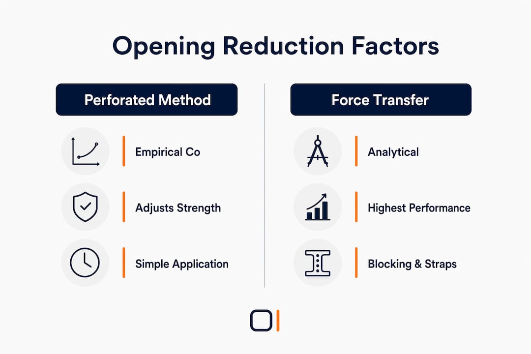
The perforated shear wall method uses an empirical reduction factor, Co, to account for the presence of openings without requiring detailed force analysis at each opening. The wall is treated as a unit, and the Co factor reduces the overall capacity based on opening geometry. This method simplifies design considerably and is well-suited for residential wood-frame construction where opening configurations are relatively standard. The tradeoff is efficiency: you may leave capacity on the table compared to a fully engineered force transfer design.
The force transfer around openings (FTAO) method is the most analytically demanding but also the highest-performing approach. Walls designed for force transfer around openings use straps, blocking, and nailing to explicitly carry shear forces across and around the opening. Full-scale tests confirm that FTAO-detailed walls outperform both segmented and perforated walls, especially as opening sizes increase.
The FTAO method also comes with a significant caution. At least three techniques fall under the definition of rational analysis for force transfer, and they can predict internal strap forces that differ by as much as 800% in extreme cases. The drag strut technique consistently underestimates strap forces. The cantilever beam technique consistently overestimates them. The Diekmann technique provides the most reliable strap force predictions for window-type openings, though it significantly overpredicts forces for large garage-type openings.
Practical considerations when selecting a design approach:
- Segmented method — use when full-height segments alone provide adequate capacity; avoids all opening analysis
- Perforated method — preferred for residential wood-frame projects with standard window and door configurations; Co tables in SDPWS make application straightforward
- FTAO method — warranted when opening sizes are large, wall length is limited, or higher stiffness is required; demands careful detailing of straps, blocking, and nailing at all four corners of each opening
- Method consistency — do not mix methods within a single wall line without engineering justification; the force assumptions differ between approaches
For reinforcement detailing under the FTAO method, blocking must be installed above and below each opening, straps connect the full-height segments to the header and sill zones, and nailing schedules at the strap connections must match the calculated force demand. The choice of strap size and nailing pattern depends directly on which rational analysis technique you use, which is why technique selection and strap design must be treated as a single decision.
Pro Tip: When using the FTAO method for garage-type openings, verify strap forces with the Diekmann technique rather than the drag strut or cantilever beam approaches. The drag strut method can underestimate strap demand enough to produce an unsafe connection.
US code requirements for openings in shear walls
IBC 2015 Section 2305.1.1 sets the foundational requirement: all openings in shear panels that materially affect their strength must be detailed on the plans, and their edges must be adequately reinforced to transfer all shear stresses. The language is clear on the obligation but deliberately silent on what size threshold constitutes "materially affecting" strength.
That silence is intentional and consequential. No universally accepted code threshold exists for what size opening triggers formal analysis and reinforcement. Engineers rely on jurisdictional precedent and engineering judgment to justify exemptions for small MEP openings. A small conduit penetration in a long shear wall may reasonably be excluded from formal analysis. A 4-inch diameter hole in a 2-foot-wide pier almost certainly cannot.
For windows and doors, the code directs engineers to the AWC SDPWS provisions covering the perforated shear wall method and the FTAO method. These are not optional analytical refinements. They are the code-recognized paths for handling openings of meaningful size in wood-frame shear walls. Applying the segmented method and simply ignoring the opening-adjacent segments is also code-compliant, but it may leave significant capacity unclaimed.
Wind load considerations add a layer of complexity that the prescriptive seismic provisions do not fully address. Wind loads can and often do exceed seismic demands, and the prescriptive approach in IBC is specifically calibrated for seismic design. Without an upper limit on opening size and using only the connections specified in the prescriptive provisions, a wall or diaphragm can be under-designed for wind. When performing an engineered analysis under ASCE 7-10 or later, the prescriptive IBC provisions should be applied with caution and verified against actual wind demand.
Code and engineering requirements for openings, summarized:
- IBC 2015 Section 2305.1.1 — openings materially affecting strength require edge reinforcement and plan documentation
- AWC SDPWS — governs perforated shear wall Co factors and FTAO detailing for wood-frame construction; see the shear wall ratio implications for wall line planning
- Small MEP openings — no universal size threshold; engineering judgment governs; caution advised when applying diaphragm-based guidance to shear walls
- Wind vs. seismic — prescriptive IBC provisions are seismic-calibrated; engineered analysis required when wind controls
- Prescriptive vs. engineered analysis — prescriptive methods are appropriate for standard configurations; engineered analysis is required for complex geometries, large openings, or high-demand conditions
- Jurisdictional variation — local amendments and precedent influence what exemptions are accepted for small openings; confirm with the authority having jurisdiction
For sheathing requirements around openings, the 2026 code guide on sheathing covers edge nailing, blocking requirements, and panel orientation details that directly affect how well shear transfers across an opening boundary.
What research and testing reveal about opening effects on shear wall performance
Full-scale wall tests conducted through the joint APA, University of British Columbia, and USDA Forest Products Laboratory research program tested twelve different wall assemblies to study how openings affect both global and local wall response. The results confirmed a clear hierarchy: segmented walls produced the lowest load factors, perforated walls performed at an intermediate level, and walls specifically detailed for force transfer around openings performed best. As opening sizes increased across all configurations, wall strength and stiffness decreased.
One finding from that test program was not expected. For walls with typical window openings, the walls with the narrowest piers based on minimum pier width in North American codes produced higher load factors than walls with full-width piers at a height-to-width ratio of 2:1. This counterintuitive result has practical implications for how engineers approach pier sizing in perforated wall design.
Failure modes in reinforced concrete shear walls with openings follow predictable patterns that the AIJ reduction factor framework attempts to capture. In laboratory tests of scaled RC specimens, walls with single-aligned openings (W1) and double-aligned openings (W2) failed through concrete crushing at the wall base and shear failure of the coupling beams above the openings. The solid wall (W0) failed in shear. These failure mechanisms are consistent with the coupled shear wall behavior that vertically aligned openings produce.
The strength data from those RC tests tells a direct story about code accuracy:
- W0 (no opening): maximum strength 318 kN, reduction factor 1.00
- W1 (single-aligned openings): maximum strength 145 kN, experimental reduction factor 0.46 vs. AIJ value of 0.59
- W2 (double-aligned openings): maximum strength 93 kN, experimental reduction factor 0.29 vs. AIJ value of 0.45
The AIJ factor underestimated strength drops in both cases, meaning the code predicted less reduction than actually occurred. For allowable stress design, the coupling beam crack widths in W2 exceeded the 0.3 mm limitation at allowable stress levels, a serviceability failure that the standard reduction factor framework does not directly address.
Research on multiple openings reveals a further gap. The AIJ method handles multiple openings by replacing them with a single enveloped opening defined by the projected length and height of all openings combined. Experimental results show that walls with different opening pitches but the same envelope produce different shear strengths, meaning the envelope method can both underestimate and overestimate capacity depending on opening arrangement. The Ono and Tokuhiro method shows better average correlation for single openings, with an average calculated-to-experimental ratio of 0.88 versus 0.69 for the AIJ method, but neither approach reliably handles multiple openings.
Key research findings for design practice:
- Vertically aligned openings require coupled shear wall analytical models; simple reduction factors underestimate strength loss and miss serviceability issues in coupling beams
- Multiple openings produce scatter that neither AIJ nor Ono and Tokuhiro methods capture; nonlinear FEM or performance-based analysis is warranted for complex configurations
- Opening pitch matters — spacing between multiple openings affects shear capacity independently of the envelope reduction factor
- Premature failure in components such as coupling beams can occur before the wall reaches its predicted ultimate strength; preventing premature failure must be verified when applying reduction factors to ultimate strength design
- Ono and Tokuhiro method outperforms AIJ for single openings but loses accuracy for multiple openings; use with awareness of its scope
- Expert guidance recommends verifying reduction factors experimentally or through nonlinear modeling for complex or multiple-opening geometries where standardized factors may be inaccurate
Understanding how structural engineering works in residential buildings provides useful context for why these opening effects matter at the system level, not just at the individual wall level.
How ShearWise Pro handles opening reduction factors in your workflow
Applying opening reduction factors manually across multiple wall lines, opening configurations, and load cases is time-consuming and error-prone. ShearWise Pro is built specifically for 1-story and 2-story wood-frame buildings and integrates opening effects directly into the calculation workflow, so you are not managing reduction factors as a separate step.
The platform organizes your project by wall lines and handles openings, full-height segments, hold-down forces, transfer straps, and story drift checks within a single coordinated workflow. When you input an opening, ShearWise Pro applies the appropriate reduction to the wall line capacity and carries that adjusted value through to the hold-down and strap force calculations. The output is a clean PDF report formatted for review coordination, not a raw spreadsheet that requires manual interpretation.

ShearWise Pro capabilities relevant to opening design:
- Wall line organization — input multiple wall lines per story with individual opening configurations
- Opening input — specify opening width, height, and position; the program applies the corresponding strength reduction
- Full-height segment tracking — the platform identifies and calculates capacity for full-height sheathed segments separately from opening-adjacent zones
- Hold-down force calculation — opening-adjusted wall capacities flow directly into hold-down force output
- Transfer strap coordination — strap forces at opening boundaries are calculated and included in the design output
- Story drift checks — drift is evaluated at the story level accounting for reduced stiffness from openings
- PDF report generation — organized output ready for plan review and coordination with other design disciplines
Pro Tip: For walls with multiple openings or non-standard opening positions, review the full-height segment list in ShearWise Pro before finalizing hold-down locations. An opening that shifts a segment below the minimum pier width threshold can change the hold-down requirement significantly.
For engineers working through complex opening configurations, the shear wall software overview covers how the platform handles edge cases including narrow piers and stacked openings. The common design mistakes guide is also worth reviewing before finalizing any wall line with openings larger than a standard window.
ShearWise Pro supports compliance with AWC SDPWS provisions and IBC requirements by keeping the reduction factor application consistent and documented. Every calculation is traceable in the PDF output, which matters when a plan reviewer or peer reviewer asks how a particular opening was handled. You can sign up to try ShearWise Pro and run your first wall line calculation without a long onboarding process.
Key Takeaways
The shear wall opening reduction factor is an empirical multiplier that can significantly reduce wall capacity for double-aligned openings, making accurate factor selection critical in lateral system design.
| Point | Details |
|---|---|
| Area ratio drives reduction | Opening area ratio is the dominant parameter; single-opening reduction factors show a clear decreasing trend with increasing area ratio. |
| Code factors can be non-conservative | Double-aligned opening experimental results showed a reduction factor of 0.29, which is significantly lower than the AIJ code value of 0.45; verify factors for critical configurations. |
| Three US design methods exist | Segmented, perforated (empirical Co factor), and force transfer around openings each offer different accuracy and detailing complexity. |
| Force transfer outperforms perforated | Full-scale tests confirm FTAO-detailed walls deliver greater stiffness and strength than perforated or segmented walls, especially with larger openings. |
| Multiple openings require refined analysis | Neither AIJ nor Ono and Tokuhiro methods reliably predict capacity for multiple-opening walls; nonlinear modeling or testing is warranted. |