
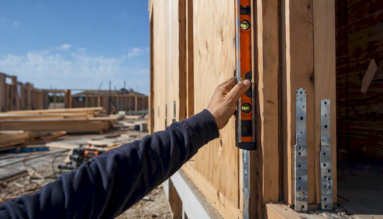
In this guide, "CMU wall" means an engineered wood-frame shear wall for 1- and 2-story residential construction. The fastest path to permit approval requires four documented outputs: shear capacity (sheathing type, thickness, and nailing schedule), deflection calculated per the SDPWS three-term equation, hold-down and tension forces summed across stacked stories, and a continuous load path narrative tied to ASCE 7, AWC SDPWS, and WFCM. Per UpCodes' design guidance, aspect ratios must stay at or below 2:1 for seismic design, or you apply the 2b/h capacity reduction. Miss any one of these and you are looking at a plan-check revision.
Minimum required deliverables at a glance:
- Nominal and adjusted shear capacity per full-height segment (plf)
- Aspect-ratio check with 2b/h reduction applied where H/b exceeds two-to-one
- Deflection calculation: bending + panel shear/nail slip + anchorage elongation vs. ASCE 7 drift limits
- Hold-down and compression chord forces, summed from all contributing stories
- Continuous load-path documentation from roof diaphragm to foundation
- Code citations: ASCE 7, AWC SDPWS, WFCM (or IRC), and applicable IBC edition
Key Takeaways
A permit-ready wood-frame shear-wall report requires shear capacity, deflection, hold-down forces, and a continuous load-path narrative, all tied to ASCE 7, AWC SDPWS, and WFCM by section number.
| Point | Details |
|---|---|
| Aspect-ratio check is mandatory | Apply the 2b/h reduction to every segment where H/b exceeds 2:1; omitting it is a top plan-check flag. |
| Three-term deflection required | Include bending, panel shear/nail slip, and anchorage elongation; compare the total to the ASCE 7 drift limit. |
| Hold-downs sum across stories | Collect overturning contributions from every story above and document the dead-load offset per SDPWS. |
| Load-path narrative matters | Drawing callouts and a written load-path narrative are as important to reviewers as the equations themselves. |
| ShearWise Pro automates the checklist | The platform covers aspect-ratio reductions, hold-down summation, deflection outputs, and annotated PDF export in one workflow. |
Table of Contents
- What building officials expect in a permit-ready shear-wall report
- Which codes and tables must you cite?
- Step-by-step workflow for shear capacity, hold-downs, and deflection
- Common mistakes and QA checks before you submit
- What to include in the permit PDF
- How ShearWise Pro maps to the permit checklist
- Worked example: one full-height segment
- How to validate and sign off the report
- Why structured workflows outperform ad hoc spreadsheets
- ShearWise Pro: permit-ready reports from your first wall line
- Sources
What building officials expect in a permit-ready shear-wall report
Plan checkers work from a mental checklist. Give them everything on it and your submittal moves forward. Miss an item and it comes back.
Calculation outputs:
- Nominal unit shear capacity (plf) from the applicable SDPWS or WFCM table, with panel grade, thickness, and edge-nailing spacing stated
- Adjusted capacity after aspect-ratio reduction (2b/h factor when H/b > 2:1)
- Three-term deflection result (inches) compared to the ASCE 7 allowable story drift
- Hold-down tension demand and compression chord force per segment, with dead-load offset documented
- Story drift check for each wall line
Construction assumptions explicitly stated:
- Sheathing type, grade, and thickness (e.g., 15/32" Structural I OSB)
- Edge and field nailing spacing and fastener penetration into framing
- Blocking at panel edges (required for most tabulated values)
- Framing species and specific gravity used for table lookup
Files and attachments:
- Annotated plan excerpt showing wall-line locations, shear direction arrows, full-height sheathing lengths, and hold-down callout symbols
- Calculation appendix with equations, table references, and numeric results
- Code sections cited by number (e.g., SDPWS Section 4.3, ASCE 7 Table 12.12-1)
- Engineer signature and stamp page
Which codes and tables must you cite?
Three standards control the calculation. Each one covers a distinct piece of the design.
ASCE 7 sets the seismic and wind demand and the allowable story drift limits your deflection calculation must satisfy. Reference the seismic design category, the response modification coefficient, and Table 12.12-1 for drift limits.
AWC SDPWS is the primary design standard for wood shear walls. It provides unit shear capacity tables and the deflection equations that govern panel type, fastener spacing, and penetration requirements. SDPWS Table 4.3A and 4.3B list allowable shear values in plf for various sheathing and nailing combinations. Always confirm whether your project is seismic-controlled or wind-controlled before selecting the table column.
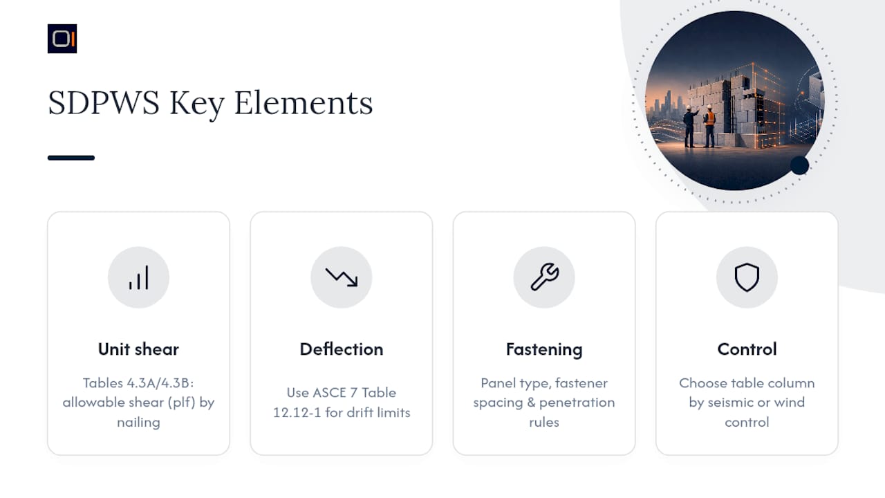
WFCM and IRC provide prescriptive tables for minimum full-height sheathing lengths and perforated shear wall rules. The perforated shear wall (PSW) method uses opening area ratios to derive an effective shear strength factor, and WFCM lists tabulated effective shear ratios and minimum sheathing-length rules. When H/b exceeds 2:1, multiply nominal unit shear by 2b/h or redesign the segment.
Pro Tip: Always note the code edition on the cover page. IBC 2021 references SDPWS 2021 and ASCE 7-22; IBC 2018 references SDPWS 2015 and ASCE 7-16. Mixing editions is a common plan-check flag.
Step-by-step workflow for shear capacity, hold-downs, and deflection
-
Collect geometry and loads. Identify all wall lines and pier segments. Record story weights, diaphragm tributary areas, roof dead and live loads, floor weights, and snow loads. This data feeds both the lateral demand calculation and the dead-load offset for hold-down sizing.
-
Assign sheathing and nailing; calculate nominal capacity. Select panel type, thickness, and edge-nailing spacing. Look up the nominal unit shear (plf) from SDPWS Table 4.3A or 4.3B. Apply the species adjustment factor if your framing is not Douglas Fir-Larch. Then run the aspect-ratio check: if H/b > 2:1, multiply the nominal value by 2b/h. Segments with H/b > 3.5:1 are not permitted for seismic design.
-
Distribute shear across the wall line. When multiple segments share a wall line, use either the equal-deflection method or the simplified shear-distribution method. WoodWorks guidance explains both: equal-deflection assumes connected walls move together and limits combined capacity by relative stiffness; simplified distribution allocates shear in proportion to adjusted segment capacity. Assuming equal load sharing across unequal segments is one of the most common errors in residential shear-wall design.
-
Calculate hold-down demands. Sum overturning contributions from each story above. For engineered design per SDPWS, a substantial portion of the design dead load may offset overturning, which can meaningfully reduce required hold-down sizes. Document the dead-load offset explicitly; reviewers will look for it.
-
Calculate deflection. Use the SDPWS three-term equation: end-post bending (8vh³/EAb), panel shear with nail slip (vh/Gt), and anchorage elongation (h·da/b). The SDPWS deflection expression requires all three terms; omitting anchorage elongation is a frequent error. Compare the total to the ASCE 7 allowable drift for your seismic design category.
-
Assemble the calculation appendix and drawing callouts. Every calculated force must trace back to a drawing callout, and every callout must trace forward to a code table. Per PHRC/Penn State research, clear load-path documentation reduces plan-check delays as much as the calculations themselves.
Pro Tip: For the perforated shear wall method, hold-downs are required only at wall-line ends rather than at each opening. This can reduce hardware and installation complexity, but verify that your total sheathing length still meets WFCM minimum requirements.
Common mistakes and QA checks before you submit
Errors that trigger plan-check revisions tend to cluster around three areas: hold-down summation, stiffness assumptions, and deflection terms.
Common errors:
- Summing hold-down forces from only the top story and missing contributions from stories below
- Assuming equal stiffness for segments with different lengths or sheathing schedules
- Omitting the anchorage elongation term from the deflection calculation
- Reporting fastener penetration based on nominal framing thickness rather than actual dressed size
- Using the wrong species adjustment factor for the framing on site
Quick QC actions:
- Compare summed story shear demand to total wall-line capacity; the ratio should be ≤ 1.0 with margin
- Run a simple overturning moment balance to sanity-check hold-down totals before finalizing hardware
- Confirm aspect-ratio adjustments are applied to every segment where H/b > 2:1, not just the shortest one
- Verify the deflection result uses the actual hold-down device elongation value from the manufacturer's table, not a generic estimate
Transfer detailing is the single most common plan-check flag in multi-story residential shear-wall submittals. Document transfer straps, floor-to-floor load-path continuity, and reentrant corner details explicitly in both the calculation appendix and the drawing callouts. A calculation that is correct but silent on transfer details will come back for revision.
What to include in the permit PDF
A complete submittal has four components. Every item in the calculation appendix should map to a drawing callout, and every drawing callout should map to a code table.

Cover page and project metadata: project address, applicable code edition (IBC year, SDPWS edition, ASCE 7 edition), design basis (ASD or LRFD), engineer of record name, license number, and stamp/signature.
Annotated plan excerpts: wall-line locations with shear direction arrows, full-height sheathing lengths dimensioned, hold-down callout symbols keyed to the calculation table, and transfer strap locations at floor lines.
Calculation appendix: input summary, per-segment capacity table, deflection steps, hold-down derivations, and load-path narrative.
| Calculation Output | Drawing Callout | Code / Table Cited |
|---|---|---|
| Nominal unit shear (plf) | Sheathing schedule note on plan | SDPWS Table 4.3A or 4.3B |
| Aspect-ratio reduction factor | Segment length dimension | SDPWS Section 4.3.4 |
| Deflection (inches) | Story drift note | SDPWS Eq. 4.3-1; ASCE 7 Table 12.12-1 |
| Hold-down tension demand (kips) | HD symbol at segment end | SDPWS Section 4.3.6 |
| Transfer strap force (kips) | Strap callout at floor line | WFCM Section 3 |
How ShearWise Pro maps to the permit checklist
Producing a permit-ready shear-wall report manually means managing geometry inputs, table lookups, stiffness distributions, hold-down summations, and deflection equations across multiple worksheets. Each handoff between steps is an opportunity for a unit mismatch or a missed adjustment factor.
ShearWise Pro organizes this as a single, connected workflow:
- Wall-line input: enter wall geometry, openings, and full-height segment lengths in one place; the platform tracks segment boundaries automatically
- Segmented and perforated methods: choose the design approach per wall line; aspect-ratio reductions and 2b/h factors are applied automatically
- Hold-down summation: forces from stacked stories accumulate in an annexed table, with dead-load offset documented per SDPWS
- Deflection equation output: all three SDPWS terms are calculated and displayed with the ASCE 7 drift comparison
- Annotated PDF export: the report includes drawing callouts, a calculation appendix, embedded code citations (SDPWS, WFCM, ASCE 7), and a signature page ready for engineer stamp
Automation also improves traceability. Every output in the PDF ties back to a specific input and a specific code table, which is exactly what plan checkers look for. You can validate the workflow with a free trial that produces three watermarked reports before any subscription commitment.
Worked example: one full-height segment
Inputs:
- Wall height: 9 ft; segment width: 4 ft (H/b = 2.25:1)
- Sheathing: 15/32" Structural I OSB, one side
- Edge nailing: 8d common at 4" o.c.; field nailing at 12" o.c.
- Framing: Douglas Fir-Larch
- Design story shear demand: 380 plf (ASD, seismic-controlled)
- Gravity dead load on segment: 3.5 kips
Calculations:
- Look up nominal unit shear from SDPWS Table 4.3A: a nominal value is given for 15/32" Structural I, 8d at 4" edge spacing, DFL framing.
- Aspect-ratio check: H/b exceeds two-to-one. Apply 2b/h factor accordingly.
- Adjusted capacity is calculated and compared to demand; segment passes.
- Hold-down tension demand is calculated considering overturning moment and dead-load offset; net overturning force may be zero or compression.
- Deflection calculation uses SDPWS three-term equation with assumed parameters. Resulting deflection is significantly less than the ASCE 7 drift limit for this seismic design category, indicating the segment passes.
How to validate and sign off the report
- Independent re-run of critical numbers. Have a second reviewer recalculate total story shear demand, the limiting segment capacity, and hold-down totals using only the input summary table. Discrepancies larger than rounding indicate a formula or reference error.
- Sensitivity check on sheathing capacity. Shift the nominal unit shear ±10% and re-run the distribution. If the wall line fails at −10%, the design has insufficient margin and the sheathing or nailing schedule should be upgraded.
- Worst-case overturning check. Re-run hold-down sizing with minimum dead load (no live load offset). Confirm the specified hold-down device capacity covers this case.
- Sign-off checklist before stamping:
- All code citations present by section number and edition
- Drawing callout IDs match calculation table row IDs
- Continuous load-path narrative covers roof to foundation
- Deflection results compared to ASCE 7 limits with the comparison stated explicitly
- Engineer signature and stamp page included and dated
Using a structural calculator that embeds code citations in its output reduces the sign-off checklist to verification rather than reconstruction.
Why structured workflows outperform ad hoc spreadsheets
Ad hoc spreadsheets are not the problem. Undocumented ad hoc spreadsheets are. The real risk in residential shear-wall work is not that an engineer makes a calculation error; it is that the error is invisible because the spreadsheet has no audit trail, no embedded code citations, and no consistent unit labeling. Plan checkers cannot verify what they cannot trace.
Structured software removes the specific friction points that generate revision requests: mismatched units between the calculation appendix and the drawing callouts, missing anchorage elongation terms, and hold-down totals that do not reconcile across stories. These are not exotic errors. They appear in experienced practitioners' submittals because the manual workflow has too many handoffs.
Engineering judgment still governs every parameter choice. Software does not decide whether a segment is feasible or whether the load path is rational. What it does is eliminate the arithmetic layer so that judgment can focus on the design rather than the bookkeeping.
ShearWise Pro: permit-ready reports from your first wall line
Permit submittals for wood-frame shear walls require every item on the checklist above: aspect-ratio reductions, hold-down summations, three-term deflection, annotated drawing callouts, and embedded code citations. ShearWise Pro delivers all of it in a single export.

The shear wall calculator handles wall-line input, segmented and perforated design methods, automatic 2b/h reductions, story-by-story hold-down accumulation, and SDPWS deflection outputs. The PDF report includes a calculation appendix with code citations and a signature page ready for your stamp. The free trial gives you three watermarked reports with no subscription required. Start with a single wall line, verify the output against your manual check, and confirm the workflow fits your submittal before committing. Sign up at ShearWise Pro or review the tutorial videos to get your first report exported in one session.
Sources
Use the sources below to cite specific calculations in your permit appendix. Match each source to the calculation it governs.
- Design of Wood Shear Walls | UpCodes
- Calculating the capacity of multiple shear walls in a line - WoodWorks
- Shear wall design in residential construction: comparison of methods | PHRC / Penn State