

In structural engineering for 1–2 story wood-framed residential buildings, "segmental retaining walls" refers to full-height shear-wall segments used as the primary lateral-force-resisting elements, not modular concrete block systems. Your deliverable for the AHJ is a permit-ready shear-wall segment report covering wall geometry, sheathing and fastener schedules, stud species and spacing, applied wind and seismic loads, chord tension and compression calculations, hold-down forces, and a documented continuous load path. Calculations must follow Allowable Stress Design (ASD) per AWC NDS and SDPWS for most residential wood-frame projects.
Before you open the calculation sheet, gather these inputs:
- Architectural plan sheets with wall line locations and dimensions
- Diaphragm tributary widths for each wall line (roof and floor)
- Design wind and seismic loads per ASCE 7 and local jurisdiction requirements
- Stud species, grade, size, and spacing from framing plans
- Sheathing type, panel thickness, and fastener schedule
Table of Contents
- What must a permit-ready shear-wall segment report include?
- How do you calculate shear-wall segments step by step?
- When should you use IRC prescriptive tables vs. AWC SDPWS engineering?
- What causes permit rejections for shear-wall segment reports?
- Worked example: 1-story and 2-story shear-wall segment calculations
- How should you show shear-wall segments on permit drawings?
- What does a permit-ready shear-wall report cost and how long does it take?
- Which tools and standards should you use for shear-wall segment reports?
- Key Takeaways
- What experienced shear-wall designers know that the code doesn't say
- ShearWise Pro cuts the time from plan to permit-ready report
What must a permit-ready shear-wall segment report include?
A complete report gives reviewers everything they need without sending an RFI. WoodWorks guidance identifies collectors and transfer elements as the most frequently omitted items in permit submittals, so build your report around load path continuity from the start.
Required content pages:
- Wall line plan with labeled segment IDs (SW-1, SW-2…), lengths, story heights, and any horizontal offsets between stories
- Sheathing type, panel thickness, and nailing schedule for each segment
- Stud species, size, and spacing, including end-zone provisions per WFCM sample tables
- Hold-down and anchor bolt details with washer bearing area calculations
- Collector, chord, and transfer strap locations with fastener schedules
- Diaphragm tributary load inputs for each wall line
- Story drift check results with deflection limits
Supporting calculation pages:
- Assumptions table: load combinations (ASD), reduction factors, material grades
- Wind and seismic load derivations referencing ASCE 7 and IBC
- Unit shear capacity tables from SDPWS Table 4.3A (or WFCM prescriptive tables)
- Chord tension and compression calculations
- Hold-down sizing and uplift checks
- Sealed conclusion page stating code compliance
Report format: cover sheet, table of contents, annotated plan snapshots with callouts, calculation pages cross-referenced to standard table numbers, and a stamped/sealed conclusion.
How do you calculate shear-wall segments step by step?
Follow this sequence to keep calculations organized and reviewer-friendly.
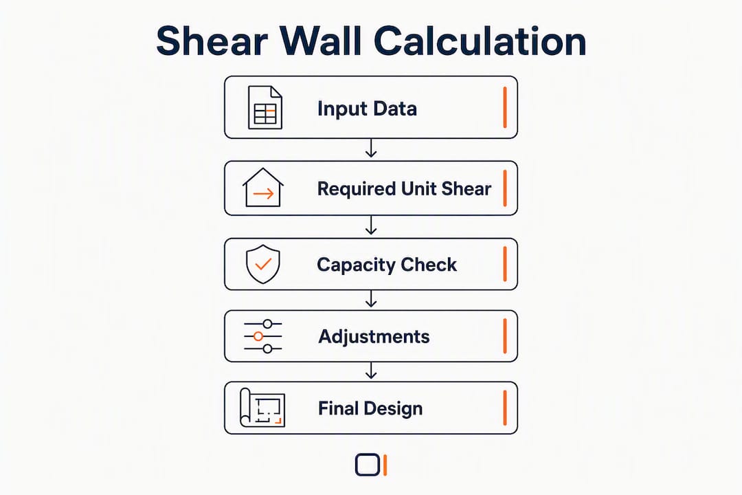
- Identify wall lines and segments. Mark full-height sheathed segments on the plan. Label each segment with a unique ID and record its length and height.
- Collect tributary diaphragm loads. Determine the tributary width for each wall line at roof and floor levels. Compute the diaphragm shear (plf) delivered to each line.
- Compute required unit shear. Divide the total lateral load on the wall line by the sum of segment lengths to get required unit shear (plf) for wind and seismic cases separately.
- Determine nominal and adjusted capacities. Pull nominal unit shear from SDPWS tables, then apply aspect ratio adjustments for any segment where h/b exceeds 2:1 and sheathing configuration factors as required.
- Distribute shear across segments. Use the equal-deflection method or strength-proportion method per SDPWS to assign demand to each segment in the wall line.
- Calculate chord tension and compression. Apply the SDPWS chord force formula: T = V × h / b, where V is segment shear, h is wall height, and b is segment length.
- Size hold-downs and anchor bolts. Compute overturning demand at each segment end. WFCM examples show anchor bolt uplift resistance using washer net area and spacing limits as an acceptable alternative to proprietary hold-downs when explicitly documented.
- Perform story drift and deflection checks. Verify that calculated deflection stays within the limits set by IBC and SDPWS for the story height.
- Document assumptions and code references. Record every table number, adjustment factor, and load combination used so reviewers can cross-check without guessing.
Pro Tip: Run wind and seismic cases separately and include both in the report. Flag the controlling case with a brief note explaining why it governs — reviewers appreciate the transparency and it reduces follow-up questions.
| Calculation step | Key input | Standard reference |
|---|---|---|
| Required unit shear | Tributary diaphragm shear, segment lengths | ASCE 7, SDPWS §4.3 |
| Nominal capacity | Sheathing type, thickness, nailing schedule | SDPWS Table 4.3A |
| Aspect ratio adjustment | h/b ratio per segment | SDPWS §4.3.4 |
| Chord tension/compression | Segment shear, height, length | SDPWS §4.3.6 |
| Hold-down / anchor bolt | Overturning demand, washer net area | WFCM |
| Story drift | Deflection formula, story height | SDPWS §4.3.2 |
When should you use IRC prescriptive tables vs. AWC SDPWS engineering?
The short answer: use IRC/WFCM prescriptive tables when the plan is simple and conventional; switch to AWC SDPWS engineering when openings, irregular layouts, or larger tributary widths push the project outside prescriptive limits.
Prescriptive path (IRC/WFCM):
- Works well for regular floor plans with limited openings and standard stud spacing
- Faster to document; tables directly specify required wall lengths
- Less flexibility — any deviation from table assumptions requires engineering
Engineering path (AWC SDPWS):
- Allows aspect ratio adjustments, opening corrections, and equal-deflection distribution
- Engineered SDPWS calculations are typically more efficient than prescriptive paths for complex layouts with many openings, often reducing required wall length while increasing calculation detail
- Increases reviewer scrutiny — every adjustment factor must be shown explicitly
When a project sits close to a prescriptive table limit, run both the prescriptive check and the engineering calculation and include both in the report. Document any AHJ pre-submittal discussion in the report narrative. Showing the comparison removes ambiguity and signals thoroughness to the reviewer.
What causes permit rejections for shear-wall segment reports?
Most rejections trace back to gaps in load path documentation, not errors in shear capacity math.
Frequent rejection triggers:
- Missing collector and chord sizing calculations
- No transfer strap details at floor-to-wall connections
- Story offsets greater than 4 feet between stories without load-path justification — WFCM explicitly defines the 4-foot offset rule for shear wall line continuity
- Inconsistent unit shear units (plf vs. lb) across calculation pages
- Unlabeled sheathing or fastener schedules on plan sheets
- Aspect ratio corrections missing for segments where h/b exceeds 2:1
- Treating perforated and segmented walls interchangeably without drag strut details
Internal QA checklist before submission:
- Verify wall line continuity from roof diaphragm to foundation on every load path.
- Confirm sheathing thickness and fastener schedule match SDPWS/WFCM table assumptions.
- Check stud species, grade, and spacing against the assumptions table in the report.
- Show anchor bolt spacing and washer bearing area calculations explicitly.
- Include the controlling load case (wind or seismic) with a one-sentence explanation.
- Confirm all segment IDs on plan sheets match the IDs in calculation tables.
Worked example: 1-story and 2-story shear-wall segment calculations
1-story example
Assume a single-story residence with Wall Line A running 24 feet. Two full-height segments are identified: Segment A1 at 4 feet and Segment A2 at 6 feet. Tributary diaphragm shear delivered to the line is 3,200 lb (wind governs). Required unit shear equals total tributary diaphragm shear divided by the sum of segment lengths.
Nominal capacities and aspect ratio adjustments are taken from SDPWS tables, with no reduction needed at h/b ratios of 2.0 or less. Chord tension is calculated by multiplying segment shear by the wall height divided by segment length. Hold-down demand is based on chord tension, with hold-down selection guided by corresponding anchor bolt and washer area calculations per WFCM.
2-story stacking differences
For a 2-story plan, ensure wall lines maintain horizontal alignment between stories according to code requirements that limit offsets. Compute shear distribution by story separately, then stack chord forces cumulatively. Story drift must be checked at each level. Document any offset with explicit collector and transfer strap details.

| Segment | Length (ft) | Required unit shear (plf) | Nominal capacity (plf) | Adjusted capacity (plf) | Required hold-down (lb) |
|---|---|---|---|---|---|
| A1 | 4 | — | — | — | — |
| A2 | 6 | — | — | — | — |
| B1 (2nd story) | 5 | — | — | — | — |
Note: Adjusted capacity reflects no aspect ratio reduction needed at h/b ≤ 2:1. Verify SDPWS Table 4.3A values for your specific sheathing and nailing configuration.
Required plan callouts on the drawing:
- Segment IDs with lengths and full-height sheathing extents
- Collector and chord locations with fastener schedules
- Hold-down symbols keyed to a schedule
- Transfer strap locations at floor-to-wall connections
How should you show shear-wall segments on permit drawings?
Clear drawing callouts cut reviewer questions before they start. Proper segment identification on plan sheets is one of the fastest ways to reduce RFI cycles.
Plan sheet callouts:
- Label each shear wall line (SW-1, SW-2…) and mark segment lengths with full-height sheathing extents
- Note stud species and spacing directly on the plan or in a general notes table
- Mark collector, chord, and transfer strap locations with fastener schedules
Detail sheets to include:
- Hold-down detail showing anchor bolt diameter, embedment, and washer size
- Collector splice and strap detail at floor diaphragm connections
- End-zone blocking detail
- Diaphragm-to-shear-wall connection detail
Pro Tip: Add a small table directly on the plan sheet listing each segment ID, its length, and the controlling unit shear (plf). Reviewers can match that table to your calculation pages in seconds, which keeps the review moving.
What does a permit-ready shear-wall report cost and how long does it take?
Turnaround and cost depend on plan complexity, number of wall lines, and whether SDPWS engineering or prescriptive WFCM work is required. AHJ plan check times are separate and vary by jurisdiction.
| Project tier | Typical delivery | Relative cost drivers |
|---|---|---|
| Simple 1-story, regular layout | 1–3 business days | Few wall lines, prescriptive WFCM path, complete inputs |
| Moderate 2-story, some openings | 3–5 business days | SDPWS engineering required, stacking checks, more segments |
| Complex irregular plan | 5–7 business days | Many offsets, large tributary widths, custom load combinations |
Key cost drivers:
- Number of wall lines and segments
- Openings and story offsets requiring load-path details
- SDPWS engineering vs. prescriptive WFCM path
- Segmented methods require separate hold-downs at each segment end, increasing hardware and detailing costs compared with perforated methods
- Rush delivery requirements
Which tools and standards should you use for shear-wall segment reports?
Calculation tools:
- ShearWise Pro organizes wall-line tables, tributary load inputs, SDPWS/WFCM capacity checks, chord and hold-down outputs, and exports sealed PDF reports formatted for AHJ review — the focused option for 1–2 story wood residential work
- WoodWorks provides free guidance documents and presentations on shear walls and diaphragms, including load path detailing for residential construction
Standards to cite in every report:
- AWC SDPWS (nominal capacities, aspect ratio adjustments, distribution methods)
- AWC WFCM (prescriptive tables, stud selection, anchor bolt checks)
- ASCE 7 and IBC (load definitions and combinations)
Author and credentials: Reports authored by Evalin carry professional credentials and experience in residential shear-wall design. Include the author's license number and seal on the conclusion page.
Templates and tutorials: Review the ShearWise Pro sample report to see how wall-line tables, calculation pages, and plan callouts are formatted for AHJ submissions, and use the tutorial library to work through the report assembly process step by step.
Key Takeaways
A permit-ready shear-wall segment report requires documented wall geometry, SDPWS-based capacity checks, chord and hold-down calculations, and a clear continuous load path from roof to foundation.
| Point | Details |
|---|---|
| Continuous load path first | Document collectors, chords, and transfer straps — reviewers accept shear math when the load path to the foundation is clearly shown. |
| 4-foot offset rule | Wall lines that shift more than 4 feet horizontally between stories require explicit load-path details or the report will be rejected. |
| Segmented vs. perforated | Segmented methods require hold-downs at segment ends, which generally increase hardware and detailing requirements compared with perforated methods. Never treat the two methods interchangeably without drag strut details. |
| Control case documentation | Run wind and seismic separately; include the governing case with a brief explanation in the report. |
| ShearWise Pro | Organizes wall-line tables, hold-down outputs, and sealed PDF reports for 1–2 story wood residential permit submittals. |
What experienced shear-wall designers know that the code doesn't say
The code tells you what to calculate. It does not tell you how to present it so a plan reviewer approves it on the first pass.
The most common friction point is not a wrong number — it is a correct number with no visible connection to the plan. A reviewer who cannot trace the load from the roof diaphragm down to the anchor bolt in under two minutes will send an RFI. That costs you days, not hours. The fix is simple: put a segment ID table on the plan sheet, cross-reference every calculation row to a plan callout, and include a one-page assumptions summary at the front of the report.
The second underestimated issue is the prescriptive-versus-engineering decision. Many designers default to SDPWS engineering because it feels more rigorous, then submit reports that are harder to review because every adjustment factor needs justification. For a straightforward plan, a clean prescriptive WFCM submission with a brief narrative explaining why all prescriptive limits are met is often faster to approve. When the plan is genuinely complex, run both checks and show the comparison. That one extra page removes the reviewer's biggest question before it is asked.
Early AHJ coordination on unusual layouts, story offsets near the 4-foot limit, or jurisdictions with local amendments pays back more time than any calculation shortcut.
ShearWise Pro cuts the time from plan to permit-ready report
Assembling a shear-wall segment report manually means rebuilding the same wall-line tables, hold-down schedules, and calculation pages on every project. ShearWise Pro eliminates that repetition. You enter wall line geometry, tributary loads, sheathing and fastener data, and stud species once, and the platform generates organized SDPWS/WFCM capacity checks, chord and hold-down outputs, and a clean sealed PDF report formatted for AHJ review.

The free trial gives you three complete watermarked reports so you can verify the output format before committing. For teams producing multiple residential submittals per month, the subscription pays back in hours saved on the first complex 2-story plan. Start your free trial at ShearWise Pro or review a sample sealed report to see exactly what the AHJ will receive.