
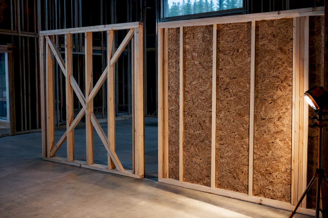
Braced wall panels are the IRC prescriptive solution; shear walls are engineered IBC/ASCE/SDPWS solutions used when prescriptive panels can't deliver enough bracing. Large openings, high seismic design categories, high wind speeds, or geometry outside IRC scope all push a project from R602.10 tables into engineered design. APA guidance and tools like ShearWise Pro exist for exactly that handoff.
TL;DR:
- Prescriptive braced wall panels usually meet the IRC minimum width of around 48 inches without calculations, while engineered shear walls can be as narrow as 27.5 inches with proper sizing.
- Engineered shear walls require detailed load calculations, hardware schedules, and often a stamped report, unlike the simple diagrams and tables for prescriptive panels.
- Large architectural openings, high seismic categories, wind speeds above thresholds, irregular geometries, or multi-unit occupancy often push projects into engineered shear wall territory.
- Fastening schedules differ significantly, with engineered shear walls needing tighter nail spacing and hold-down hardware at panel ends to resist overturning forces.
- Proper submittal documentation is critical; prescriptive submissions need a clear wall diagram and bracing table, while engineered ones require detailed calculations, hardware specifications, and drift checks.
Table of Contents
- Braced Wall vs Shear Wall: A Side-by-Side Technical Checklist
- When Does the IRC Allow Prescriptive Bracing Instead of Engineering?
- What Are the Real Technical Differences in Fastening and Hardware?
- How Should Layout Choices Shape Bracing and Shear Wall Placement?
- What Belongs in a Permit-Ready Bracing or Shear Wall Submittal?
- How Does a Shear Wall Calculator Fit Into an Engineered Workflow?
- Where to Verify These Code Requirements Directly
- The Editorial Take: Stop Treating This as an Either/Or Choice
- Sources
Braced Wall vs Shear Wall: A Side-by-Side Technical Checklist
Every wood-framed lateral system decision starts with the same fork in the road: does the wall qualify under prescriptive IRC rules, or does it need to be engineered? The distinction is not academic. It changes what's on the drawings, what the plan reviewer expects to see, and how much liability sits on the designer's stamp.
Braced wall panels follow a prescriptive path. The IRC hands you a menu of nine bracing methods, minimum panel widths, and required bracing percentages by seismic design category and wind speed. You pick a method from the table, meet the minimums, and you're done. No calculation package required.
Shear walls follow an engineered path. You calculate actual lateral demand from wind and seismic loads per ASCE 7, then size sheathing, nailing, and hold-down hardware to resist that specific demand using the Special Design Provisions for Wind and Seismic (SDPWS). The output is a stamped calculation, not a table lookup.
Here's how the two approaches stack up on the details that matter for construction documents:
- Code basis: Braced wall panels sit under IRC R602.10; shear walls sit under IBC, referencing ASCE 7 for loads and SDPWS for wall design.
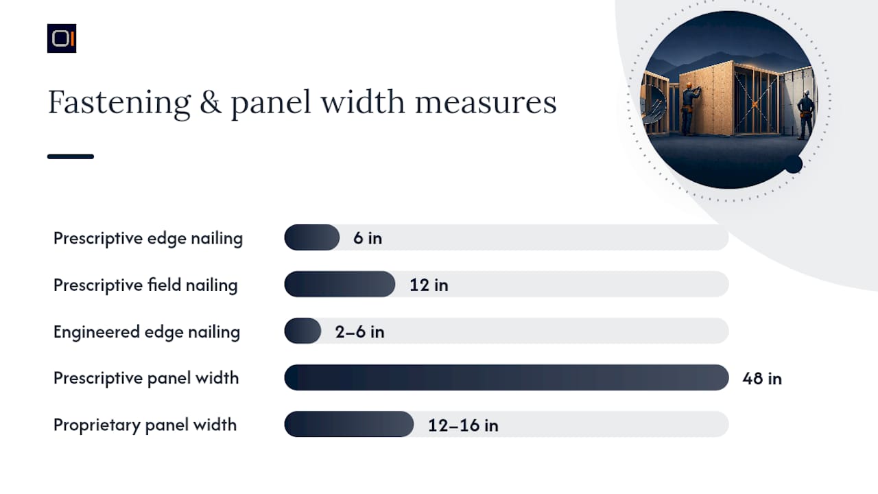
- Sheathing and nailing: Prescriptive panels typically use standard 6 inches on center edge nailing; engineered shear walls often tighten that to 2 to 6 inches on center depending on demand.
- Hardware: Braced panels rarely need dedicated hold-downs; engineered shear walls commonly require hold-downs, foundation anchors, and transfer straps sized to specific overturning forces.
- Minimum widths: IRC panels typically require around 48-inch of width for standard methods, with continuous sheathing options trading width for full-wall coverage. Engineered segments can run as narrow as about 27.5 inches when the calculation supports it.
- Aspect ratio limits: Both systems cap height-to-width ratios, but engineered design lets you push closer to the limit because the capacity is calculated, not assumed.
- Documentation expectation: Braced wall lines need a plan diagram and a bracing table; shear walls need load calculations, panel capacity checks, hold-down schedules, and often a story drift check.
- Permit implications: A reviewer accepts a braced wall line at a glance if it matches the table. An engineered shear wall needs a calculation package, typically with an engineer's stamp.
The practical rule engineers use in the field: if the architectural plan fits inside IRC's assumptions, prescriptive bracing is faster and cheaper to document. The moment an opening, a load, or a geometry pushes outside those assumptions, you're doing engineered shear wall design whether you planned to or not.
When Does the IRC Allow Prescriptive Bracing Instead of Engineering?
IRC R602.10 governs wall bracing for the vast majority of one and two-story wood-framed houses in the United States, and it's built around a simple idea: give designers a menu of proven bracing methods so most homes never need a structural engineer for lateral design. The code organizes walls into braced wall lines, then requires a minimum length of bracing along each line based on story height, wind speed, and seismic design category.
The required bracing percentage moves a lot depending on hazard level. In low-wind, low-seismic regions, R602.10 tables can call for bracing amounts around 25 percent of the wall line length. In high-wind coastal zones or higher seismic design categories, that percentage can climb past 50 percent of the same wall line. That swing alone tells you why a house that works fine prescriptively in Ohio can require full engineering in coastal South Carolina.
Nine prescriptive bracing methods exist under R602.10, ranging from let-in braces to structural sheathing panels. Most residential designers gravitate toward wood structural panel methods because they're familiar, well documented, and forgiving of minor field deviations. Continuous sheathing methods let you sheathe an entire wall line and accept narrower individual segments in exchange, which becomes useful when window and door openings eat into available panel width.
A building falls outside IRC scope, and therefore outside prescriptive bracing entirely, under several common conditions:
- The structure exceeds three stories or falls outside the height and area limits IRC allows for conventional construction.
- Wind speed or seismic design category exceeds the thresholds where R602.10 tables stop providing prescriptive solutions.
- The building includes irregular geometry, cantilevers, or offsets that the prescriptive tables don't address.
- Occupancy shifts to multi-unit or non-residential use, which routes the project to IBC regardless of size.
- Architectural openings are large enough that no combination of prescriptive panels can be placed to meet the required bracing length.
Once a project needs engineered shear walls, SDPWS offers three main design approaches. Segmented design treats each full-height sheathed piece between openings as an independent shear wall, calculated on its own merits. Perforated design treats the entire wall line as one shear wall with openings, using an adjustment factor for the openings rather than isolating each segment. Force transfer around openings, or FTAO, adds blocking and strapping to let a wall with a large opening still function as one continuous shear panel, transferring forces around the opening rather than through it.
The trigger list engineers actually use in practice comes down to four checks: seismic design category, mapped wind speed, opening size relative to available wall length, and occupancy classification. Hit any one of them hard enough, and the project moves from a table lookup to a calculation package. Wood framing lateral systems generally follow this same fork, whether the building is a single-family house or a small multi-unit structure, and understanding how lateral systems distribute load across wall lines makes the IRC-to-IBC transition easier to plan for early instead of discovering it mid-permit.
What Are the Real Technical Differences in Fastening and Hardware?
The gap between a braced wall panel and an engineered shear wall shows up first in the fastening schedule, and it's often the detail that trips up field crews used to prescriptive work. Standard braced panels typically call for 6 inch on center edge nailing and 12 inch on center field nailing with common nail sizes matched to sheathing thickness. Engineered shear walls frequently tighten that edge nailing to a range as close as 2 to 6 inches on center, because the calculated shear capacity depends directly on fastener spacing.
Hold-downs are where the two systems diverge most visibly. Prescriptive braced panels generally don't require dedicated hold-down hardware because the code assumes the bracing method itself provides adequate anchorage within its tested limits. Engineered shear walls almost always need hold-downs at panel ends to resist overturning, sized to the specific tension force the calculation produces. That force gets transferred through foundation anchors and, in multi-story construction, through straps that connect hold-downs vertically between floors.
Three factors determine whether a wall segment can even count toward required bracing, and missing any one of them is a common field mistake:
- Minimum width. The segment must meet the width threshold for its bracing method, whether that's a full 48 inch prescriptive panel or a narrower engineered segment justified by calculation.
- Full-height status. The sheathing must run continuously from bottom plate to top plate; a segment interrupted by blocking or a different assembly doesn't qualify as-is.
- Connection detailing. Nailing pattern, hold-down hardware where required, and anchor bolt spacing all have to match what the design assumes, not just what looks reasonable in the field.
A sheathed wall segment that skips any of these three doesn't automatically fail. It just falls out of the prescriptive bracing tally and has to be treated as an engineered shear wall segment, or ignored entirely if it can't be justified either way.
Panel geometry and aspect ratio limits are the next layer. Both systems cap the ratio of height to width, but where prescriptive methods use flat limits from the code tables, engineered design lets a calculation push closer to that boundary because capacity is verified rather than assumed. That flexibility is exactly why pre-engineered proprietary panels like Simpson Strong-Wall units matter in tight floor plans: they're accepted as alternate braced wall panels under IRC provisions and can deliver rated lateral resistance in widths as narrow as 12 to 16 inches, far below what a field-built prescriptive panel needs.
When an opening forces a choice among the three SDPWS-based engineered approaches, the detailing consequences differ sharply:
Segmented design isolates each full-height piece between openings and calculates it independently. It's the most straightforward to detail and explain to a reviewer, but it wastes capacity in walls with several openings because each segment has to carry its own share alone.
Perforated design treats the whole wall line as one shear wall, applying an opening adjustment factor instead of splitting it into pieces. This usually delivers more usable capacity from the same wall line, but it requires specific tension strap and anchorage detailing at the ends of the line to make the assumption valid.
Force transfer around openings adds blocking and strap connections that route force around a large opening, letting a wall function as one continuous shear panel even with a substantial window or door interrupting it. FTAO detailing is the most labor-intensive of the three on the drawings, with straps and blocking called out at every corner of the opening, but it's often the only workable option when architectural openings are large and repositioning them isn't an option. A dedicated look at strap ties in shear wall design covers how these connections get sized and specified in practice.
Pro Tip: Don't assume a sheathed segment "close enough" to 48 inches will pass as prescriptive bracing. Reviewers check exact panel width against the method table, and a 44-inch segment that looks fine on an elevation can get flagged, forcing a late-stage redesign into engineered territory.
How Should Layout Choices Shape Bracing and Shear Wall Placement?
Braced wall line spacing isn't just a floor plan decision. It directly changes how much bracing each line has to provide, since the IRC treats each braced wall line as a discrete requirement rather than distributing load across the whole building the way a full structural analysis would. Space your braced wall lines further apart, and the percentage of bracing required along each one goes up. Add an interior braced wall line, and you can sometimes redistribute enough demand to keep exterior walls with large windows below the threshold that would force engineering.
That system-level behavior is worth understanding before the architect finalizes the floor plan, not after. IRC's prescriptive approach is intentionally conservative compared with a whole-building lateral analysis, which means a layout that looks structurally reasonable can still fail a strict wall-line-by-wall-line prescriptive check even though the building as a system would perform fine under engineered analysis.
When a wall line can't hit its required panel width because of window and door placement, designers generally reach for one of three alternates:
- Pre-engineered proprietary panels in narrow widths, filling gaps between openings where a standard 48 inch panel simply won't fit.
- Continuous sheathing methods, sheathing the full wall line to unlock narrower individual segment requirements in exchange for full coverage.
- Redistribution to interior braced wall lines, shifting some of the required bracing load to an interior wall where openings are less constrained.
Diaphragm interaction adds another layer engineers can't skip. A stiffer shear wall attracts more of the diaphragm's distributed load, and mismatched stiffness between wall lines on the same story can concentrate drift where the design didn't expect it. Story drift checks exist specifically to catch that concentration before it becomes a serviceability problem, and they're a standard deliverable in any competent engineered shear wall calculation package, not an optional extra.
Coordination between disciplines matters more here than almost anywhere else in wood-framed design. Hold-down locations need to land on solid foundation without conflicting with plumbing penetrations or mechanical chases, and anchor bolt layouts have to survive the framer's actual stud spacing, not just the idealized version on the structural sheet. Getting this sequencing wrong after framing starts is one of the most common sources of costly change orders on residential projects, because moving a hold-down after the foundation is poured is a very different problem than adjusting it on paper. A broader look at lateral system components is worth reviewing early in design, before the architectural plan locks in opening locations that constrain your bracing options later.
What Belongs in a Permit-Ready Bracing or Shear Wall Submittal?
Plan reviewers see the same two failure patterns constantly: braced wall lines that aren't clearly marked on the plan, and engineered narrow panels submitted without enough backup to verify the alternate provision actually applies. Getting the submittal package right the first time avoids the review cycle that turns a two-week permit into a six-week permit.
For prescriptive braced wall panel submittals, the minimum expectation is a plan diagram showing each braced wall line location, paired with a table listing required bracing length versus provided bracing length for each line, plus the bracing method used. Reviewers want to check the math themselves in under a minute, so ambiguity about where a wall line starts and ends is the single fastest way to trigger a comment letter.
For engineered shear wall submittals, the deliverable list is longer and more calculation-heavy:
- Lateral load calculations showing wind and seismic demand per ASCE 7, tied to the project's mapped site parameters.
- Panel capacity checks for each shear wall segment, referencing the SDPWS design approach used (segmented, perforated, or FTAO).
- Hold-down force calculations and a hardware schedule identifying specific hold-down models and anchor bolt sizes at each location.
- Transfer strap details wherever force needs to move across a floor line or around an opening.
- Story drift checks confirming the building stays within serviceability limits under design loads.
A concise summary table on the plan set, listing bracing length per wall line, method used, panel widths, and anchor schedule side by side, gives reviewers exactly what they need without forcing them to dig through a calculation package for basic verification. Structural engineers who build this table into every submission report fewer review comments tied to unclear documentation, because the reviewer can confirm compliance visually instead of hunting through pages of narrative calculations.
The recurring red flags worth avoiding: braced wall lines that shift location between the architectural and structural plans, narrow alternate panels submitted without manufacturer listing documentation to justify the width, and engineered shear walls missing a hold-down schedule that ties calculated forces to specific installed hardware. Any one of these is enough to stall a submittal in review.
How Does a Shear Wall Calculator Fit Into an Engineered Workflow?
Once a project crosses into engineered shear wall territory, the deliverable list gets long fast: wall-line bracing summaries, hold-down force calculations, transfer strap schedules, story drift checks, and a clean report that ties all of it together for the reviewer. Building that package by hand in a spreadsheet works, but it's slow and easy to get inconsistent from one project to the next.
ShearWise Pro was built specifically for that gap: an online shear wall calculator for 1-story and 2-story wood-framed buildings that organizes wall lines, openings, full-height segments, hold-down forces, and transfer straps into one coordinated model. The platform generates the story drift check and exports a clean PDF report designed for exactly the kind of review coordination described in the submittal section above.
Consistent, clearly labeled reports matter more than they might seem to on paper. A reviewer working through a labeled wall-line summary with hold-down schedules laid out the same way project after project moves through it faster than one working through a hand-annotated calculation with a different format every time. That consistency is what actually shortens the review cycle, not just the accuracy of the numbers themselves.
For engineers, architects, designers, drafters, contractors, and builders moving between prescriptive and engineered work on the same set of projects, having one tool that handles the engineered side cleanly means less time reformatting calculations and more time on the design decisions that actually need judgment.
Where to Verify These Code Requirements Directly
Cross-check every number in this article against the primary source before it goes on a stamped drawing. IRC R602.10 covers braced wall line requirements and method tables directly. APA's shear wall selection handout and wall installation guidance are the standard industry references for engineered SDPWS design options. For seismic design category and mapped values, USGS design maps remain the authoritative source engineers pull from before starting any engineered shear wall calculation.
The Editorial Take: Stop Treating This as an Either/Or Choice
Most articles on this topic frame braced walls and shear walls as competing systems, as if picking one is a design philosophy. That's backwards. The IRC's prescriptive tables and IBC's engineered path aren't rivals; they're a single continuum with a hard boundary in the middle, and the code decides which side of that boundary your project falls on, not your preference.
Where conventional advice falls short is treating "engineered shear wall" as the fallback for hard projects. It's not a fallback. It's the correct tool the moment your openings, loads, or geometry exceed what a table lookup can honestly justify, and pretending otherwise is how narrow panels end up miscounted in a bracing tally.
What should change first: designers should check seismic design category and opening layout against IRC scope before the architectural plan locks in, not after framing starts. The documentation burden of engineered shear walls, done right with tools built for it, shrinks the gap that used to make prescriptive bracing feel like the easier path. It rarely is once the review cycle is counted.
— Evalin
Sources
- Handout – Shear Wall Selection for Wood-Framed Buildings (APA)
- IRC 2024 Shear Wall Bracing R602.10: Wind and Seismic Wall Requirements | Jaspector
- Engineered Wood Construction guide / Wall installation (APA panel wall sheathing materials)
- Strong-Wall® Bracing Selector: General Instructions for the Designer (Simpson Strong-Tie)