
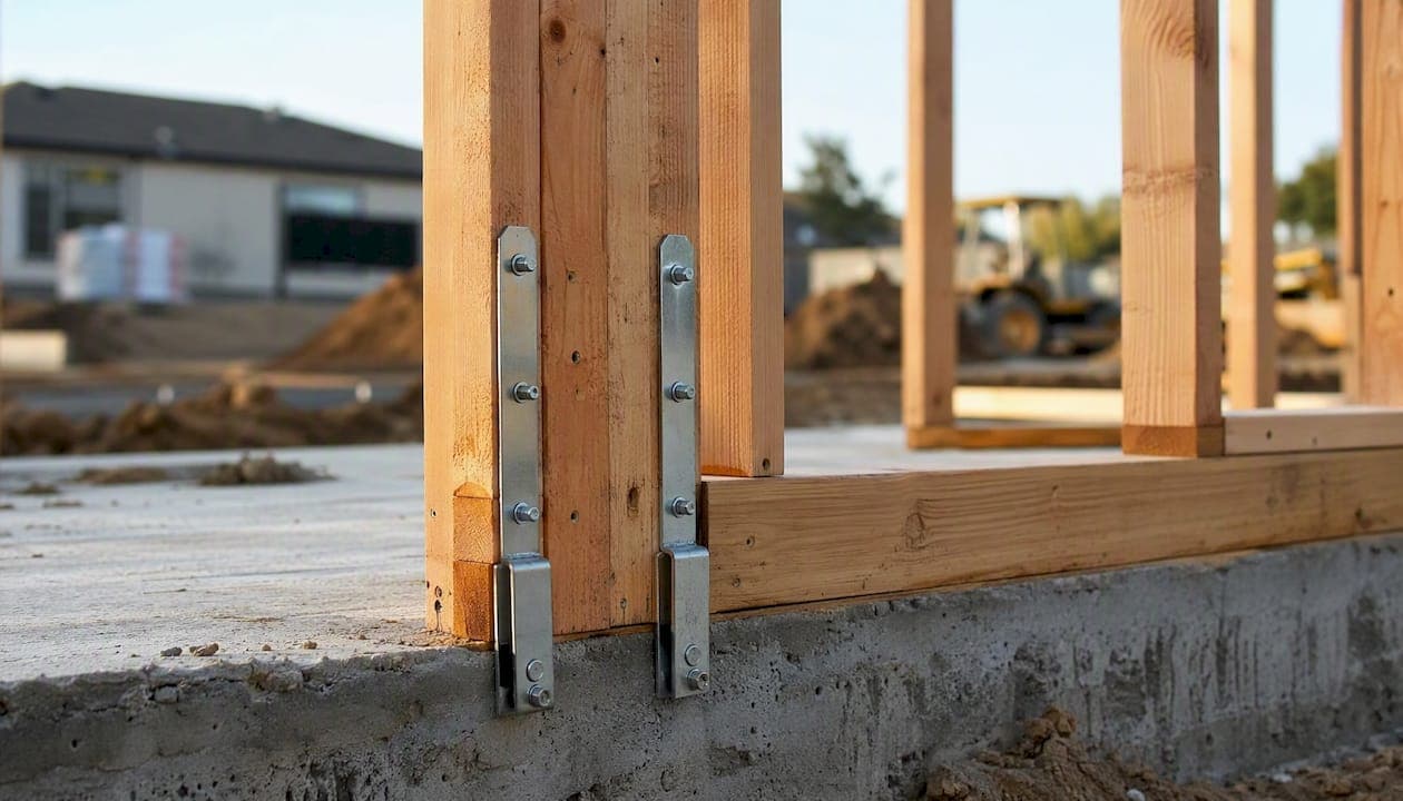
A boundary element is the reinforced end zone of a shear wall or diaphragm edge that receives and transmits concentrated tension, compression, and overturning forces to the foundation through hold-downs, straps, chords, collectors, and drag struts. Per ANSI/AWC SDPWS framing requirements, end posts shall be provided to transmit design tension and compression forces, and sheathing shall not be used to splice boundary elements. The cross-sectional area (A) of the boundary element feeds directly into deflection calculations and controls whether your wall stays within code drift limits.
Three things to confirm before you finalize permit drawings:
- Identify every boundary element on plan: wall ends, diaphragm chord edges, around large openings, and re-entrant corners.
- Verify the cross-sectional area (A) and modulus of elasticity (E) inputs in your deflection and strength checks match the actual specified lumber assembly.
- Confirm hold-down locations, anchor embed depths, and strap callouts are consistent between drawings and the calculation file.
Table of Contents
- Where do boundary elements occur on a building?
- What code and framing rules apply to boundary elements?
- How do you size boundary elements using A, E, da, and en?
- How does the design method change boundary element requirements?
- How do you detail the load path from sheathing to foundation?
- Worked example: anchorage deflection check for a built-up boundary element
- What goes into a permit-ready boundary element package?
- Tools and resources that support boundary element design
- Common mistakes that trigger permit corrections
- Key Takeaways
- The detail that actually decides permit outcomes
- ShearWise Pro speeds your boundary element workflow
Where do boundary elements occur on a building?
Boundary elements appear wherever concentrated forces collect or change direction in the lateral system. The most common locations in 1- and 2-story wood residential work are:
- Wall ends: — Every full-height shear wall segment terminates in a boundary element, typically a built-up post, that anchors overturning to the foundation.
- Diaphragm perimeter chords: All edges of a diaphragm must be supported by boundary elements, including chords and collectors that run parallel and perpendicular to the lateral load.
On plan, show the boundary element extent with a note or symbol, call out the stud build-up count and nailing schedule, and indicate hold-down hardware and strap locations with leader lines to a detail sheet.
What code and framing rules apply to boundary elements?
The governing references for residential wood boundary elements are ASCE 7 (diaphragm edge support), ANSI/AWC SDPWS (definition, framing, and splice prohibition), and the IRC/NDS for member sizing. Inspectors and plan reviewers look for the following:
- Boundary elements labeled on plan with stud count and species/grade noted.
- Minimum 2" nominal framing members for all shear wall construction, including end posts.
- Full end bearing provided at top and bottom plates; no reliance on sheathing to transfer axial load between plies.
- Hold-down type, location, and anchor bolt or embed schedule shown on drawings.
- Explicit note that sheathing shall not splice boundary elements (SDPWS language reproduced verbatim in permit notes).
- Nailing schedule between built-up plies documented to confirm composite action.
How do you size boundary elements using A, E, da, and en?
The four-term shear wall deflection equation used in SDPWS-based design separates bending, shear, anchorage, and connection deformation. Boundary element variables feed two of those terms directly.
| Variable | Definition | Typical value (2×4 DF No.2 built-up) |
|---|---|---|
| A (in²) | Net cross-sectional area of boundary element | typically two 2×4 studs |
| E (psi) | Modulus of elasticity for species/grade | typical value for Douglas Fir No.2 |
| b (ft) | Tributary wall width used in bending term | Per plan |
| da (in.) | Anchorage deflection (hold-down slip + elongation) | 0.125 in. assumed per AWC perforated wall guidance |
| en (in.) | Nail slip deformation at sheathing-to-framing connection | Per fastener schedule and load level |
The bending term uses cross-sectional area and modulus of elasticity to compute chord elongation under the overturning moment. Anchorage deflection includes hold-down device elongation, bolt slip, and bearing plate effects. Accurate estimation of anchorage deflection is important to ensure conservative drift calculations.
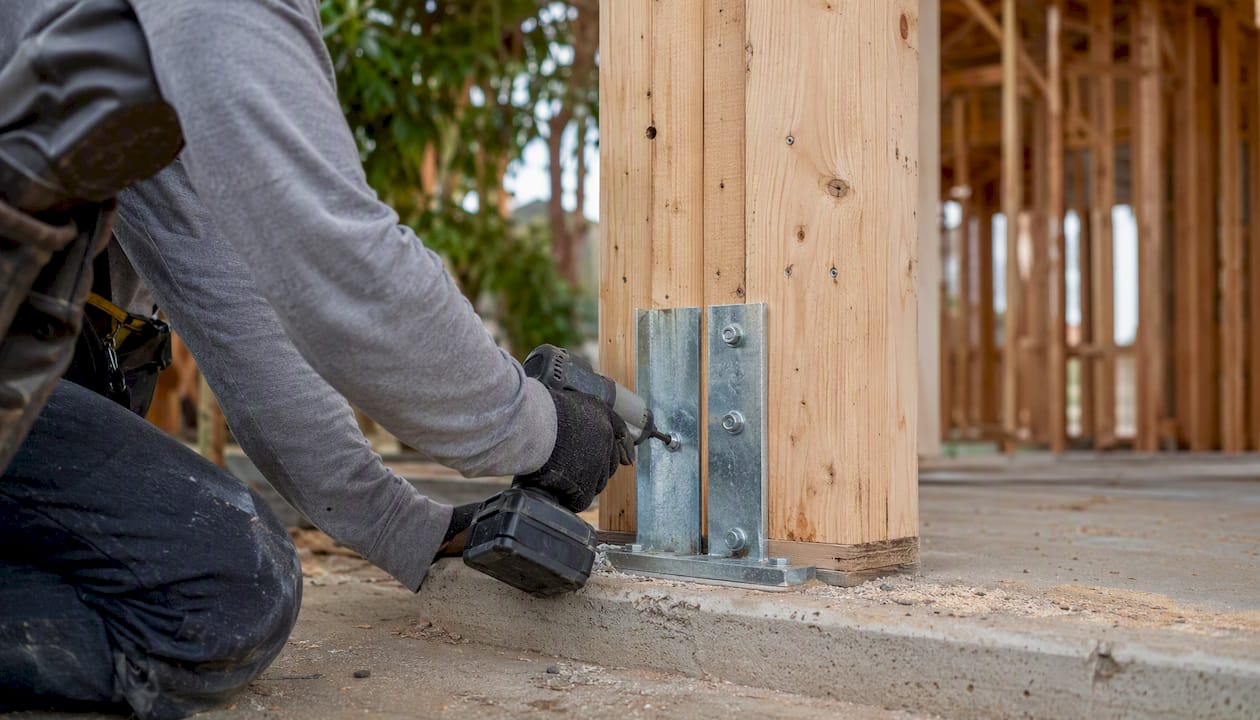
Pro Tip: When specifying built-up members, explicitly check the inter-ply nailing schedule. If the hold-down attaches to only one ply, the effective A in your deflection equation is the single-ply area, not the full built-up section, unless the nailing transfers proportional shear to each ply.
How does the design method change boundary element requirements?
The choice between segmented, perforated, and Force Transfer Around Openings (FTAO) walls changes where hold-downs go and how much detailing the boundary elements require.
| Design method | Hold-down locations | Boundary element role | Key detailing requirement |
|---|---|---|---|
| Segmented | Both ends of every full-height segment | Anchor each pier independently | Hold-down at each segment end; no continuity across openings required |
| Perforated | Wall ends only | Chord action across full wall length | Drag struts above/below openings; longer effective wall length needed |
| FTAO | Wall ends; may reduce interior hold-downs | Transfer forces around opening perimeter | Continuous sheathing, rational force summation, detailed strap schedule |
FTAO methods can reduce hold-down counts but require rational analysis, continuous sheathing, and a complete force summation at each opening corner. Perforated and FTAO walls need more detailed drag struts and longer effective lengths compared to segmented designs. For permit calcs, document pier widths, aspect ratios (h/bs), tributary opening lengths, and how you summed segment shears to determine hold-down forces. See the wall opening reduction analysis guide for a method-by-method comparison.
How do you detail the load path from sheathing to foundation?
Coordinating the full load path — sheathing to studs, studs to hold-downs, hold-downs to foundation — is where most field failures originate. Focusing only on the hold-down hardware and ignoring the connections above and below it produces walls that perform below design intent.
Show these items on every permit drawing set:
- Built-up stud array with ply count, species/grade, and inter-ply nailing schedule (nail size, spacing, and pattern).
- Hold-down type and model reference, with bolt diameter, edge distance, and anchor embed depth.
- Transfer strap locations at openings, with strap model, fastener count, and end distance callouts.
- Foundation anchor bolt or cast-in-place anchor schedule, including embed depth and plate washer size.
- Collector/chord continuity lines showing how diaphragm shear reaches the shear wall boundary.
Red flags that trigger corrections: sheathing used as the only splice between boundary element plies, hold-downs attached to a single ply without documented inter-ply nailing, missing transfer straps at opening corners, and foundation embed depths left as "per code" without a specific value. For a deeper look at load path tracing, the ShearWise Pro blog covers the step-by-step documentation process.
Worked example: anchorage deflection check for a built-up boundary element
Assumptions:
- Wall height: 9 ft; wall width (b): 4 ft
- Lumber: two 2×4 Douglas Fir-Larch No.2; A = 10.5 in²; E = 1,600,000 psi
- Applied overturning moment produces a hold-down tension demand of 3,200 lb
- Assumed anchorage deflection: da = 0.125 in. (per AWC perforated wall example)
- Connection deformation (en): 0.03 in. from fastener schedule at design load
Steps:
- Compute the bending (chord elongation) term: Δ_bending calculated per formula using input shear, height, width, area, and modulus.
- Add anchorage deflection: Δ_anchorage assumed per typical values.
- Add connection deformation: Δ_connection based on fastener schedule.
- Sum total deflection: Sum of terms representing wall drift.
- Check against code limit: Compare total deflection to code drift limit (e.g., h/240).
Result: Δ_total = 0.242 in. < 0.45 in. (h/240). Document A = 10.5 in², E = 1,600,000 psi, and da = 0.125 in. explicitly in the calculation file with the source reference (AWC perforated wall guidance).
What goes into a permit-ready boundary element package?
A complete permit submittal for boundary elements includes drawings, a calculation worksheet, and a load-path narrative. Reviewers expect to find:
- Referenced standards: — ASCE 7 (diaphragm sections), ANSI/AWC SDPWS (boundary element definition and framing), and IBC/IRC framing sections cited by section number on the calculation cover sheet.
Tools and resources that support boundary element design
Authoritative references to cite in your calculations:
- Design of wood shear walls — UpCodes
- Design for Force Transfer Around Openings (FTAO) — T555.pdf
- Requirements for built-up groups of studs at the end of shear walls — WoodWorks
- Practical considerations for shear wall connections and details — WoodWorks slides
- Perforated shear wall design — AWC
- Shear wall tables and framing requirements — University of Washington course materials
- Shearwalls and diaphragms presentation — WoodWorks (Strasser)
- Shear wall design in residential construction: a comparison of methods — PHRC (Solnosky)
For calculation and reporting, ShearWise Pro organizes wall lines, computes hold-down forces and drift checks, and exports clean PDF reports with all assumptions documented. Key features relevant to boundary element work:
- Tutorial videos covering report setup and calculation workflow.
Common mistakes that trigger permit corrections
Knowing what reviewers flag lets you fix issues before the first submittal. The most frequent problems in boundary element work, and the minimum corrective step for each:
- Assuming composite A without inter-ply nailing documentation: Add a nailing schedule between plies and confirm the hold-down attaches to all plies or that inter-ply nailing transfers the proportional load. See the common shear wall mistakes guide for a full list.
Key Takeaways
Boundary elements are the load-transferring end zones of shear walls and diaphragms; sizing them correctly for cross-sectional area (A), anchorage deflection (da), and connection deformation (en) while documenting a continuous load path is the core requirement for permit-ready residential wood design.
| Point | Details |
|---|---|
| Define and locate boundary elements | Label every wall end, diaphragm chord, opening corner, and re-entrant corner on plan with stud count and hold-down symbol. |
| Verify A and E inputs | Match cross-sectional area and modulus of elasticity to the actual specified lumber assembly and document both in the calculation file. |
| Document da and en explicitly | State the assumed anchorage deflection (da = 0.125 in. is a common starting point) and nail slip (en) with their source references. |
| Show the full load path | Trace force from sheathing through studs, hold-downs, and foundation anchors on drawings and in a one-paragraph narrative. |
| ShearWise Pro for permit reports | ShearWise Pro organizes wall lines, hold-down forces, drift checks, and exports PDF reports with all boundary element assumptions documented. |
The detail that actually decides permit outcomes
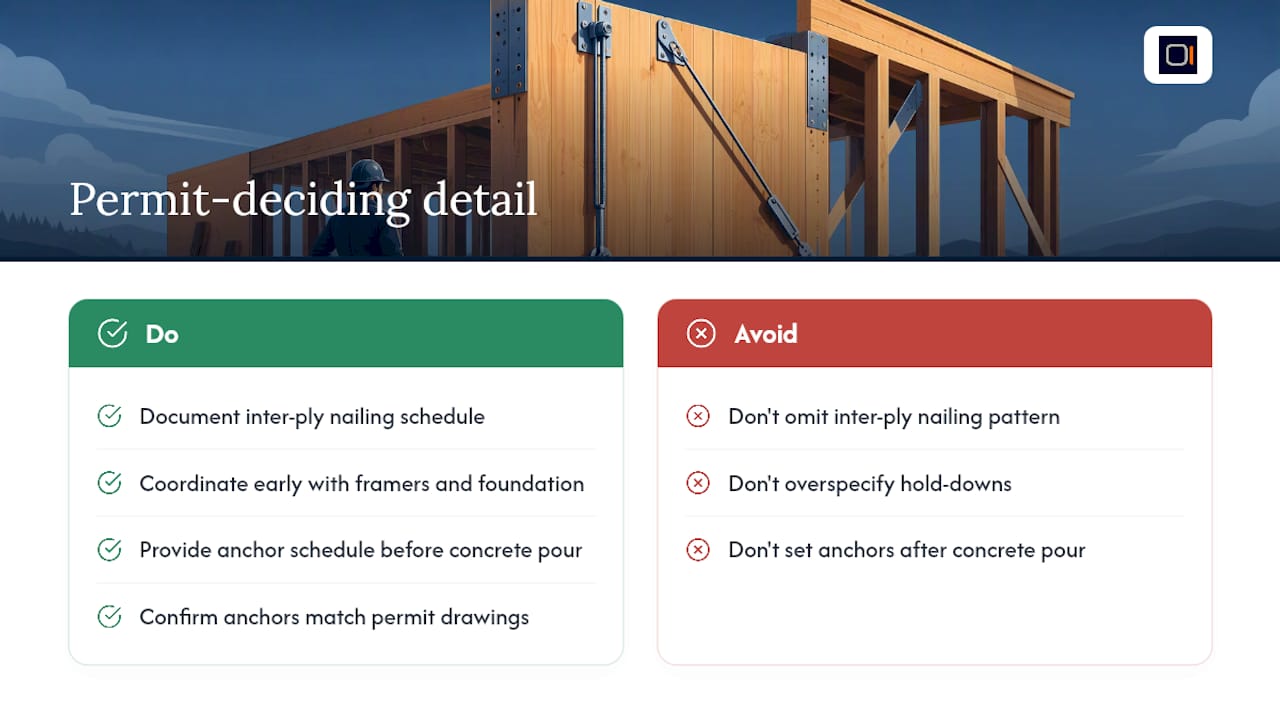
The most underestimated step in boundary element design is not the hold-down selection. It is the inter-ply nailing schedule on built-up posts. Reviewers rarely flag a hold-down model; they flag the absence of a documented nailing pattern between plies, which is the only thing that makes a two-ply or three-ply post behave as the composite section your A value assumes. Specifying a heavier hold-down to compensate for an undersized post is a common workaround that does not address the root problem.
Early coordination with framers and foundation contractors pays off here. Anchor bolt locations and embed depths need to be set before the slab or stem wall is poured. A hold-down specified on the permit drawing but installed at the wrong location or with insufficient embed is a field failure waiting to happen. Get the anchor schedule to the foundation contractor before concrete is placed, and confirm the locations match the permit drawings before the framing crew arrives.
ShearWise Pro speeds your boundary element workflow
Sizing boundary elements, tracking hold-down forces across multiple wall lines, and producing a clean permit package takes time. ShearWise Pro cuts that time by organizing every wall line, opening, full-height segment, and hold-down force in one place, then exporting a formatted PDF report with all inputs, assumptions, and code citations included.

The platform handles wall-line management, drift checks with A and E inputs per segment, strap and hold-down calculations, and report export ready for permit submittal. Start with a free trial that includes three watermarked reports, so you can run a real project through the workflow before committing to a subscription. Visit ShearWise Pro to start your trial or review the tutorial library to see the full report format.