

Shear transfer is the mechanism by which shear force moves across an interface between two structural elements or across a crack in concrete, and it governs whether that joint holds or slips. ACI 318, the fib Model Code, and platforms like ShearWise Pro all treat this as a distinct design check, separate from bending or axial capacity.
Three things to know right away:
- Where it matters most: cold joints, precast-to-cast-in-place connections, corbels, and diaphragm-to-shear-wall load paths.
- Mechanisms to check: shear-friction, aggregate interlock, cohesion, and dowel action, usually acting together rather than alone.
- Design implication: you likely need reinforcement crossing the plane, and its area is capped by code to prevent unconservative reliance on high-strength concrete alone.
Key Takeaways
Shear transfer capacity across most concrete interfaces comes from the combined action of friction, aggregate interlock, cohesion, and dowel action, governed by ACI's shear-friction provisions and their design cap.
| Point | Details |
|---|---|
| Definition | Shear transfer moves shear force across an interface, joint, or crack between structural elements. |
| Four mechanisms | Friction, aggregate interlock, cohesion, and dowel action combine to resist sliding at a plane. |
| Code cap matters | ACI limits nominal shear strength to about 0.2 f'c Ac, capping reliance on concrete strength alone. |
| Tension and skew change demand | Tension across the plane and skewed connections both reduce effective capacity versus standard assumptions. |
| Tool support | ShearWise Pro organizes wall line, strap, and hold-down calculations into permit-ready reports for wood-framed projects. |
Table of Contents
- How Does Shear Transfer Work Across an Interface?
- What Does ACI Say About Shear-Friction Design?
- Where Does Shear Transfer Show Up in Real Structures?
- How Should Engineers Check Shear Transfer in Design?
- What Do Push-Off Tests Reveal About Shear Transfer Limits?
- What Should Engineers Verify Before Finalizing a Detail?
- A Coordination Note From the Field
- A Practical Way to Organize Shear Transfer Checks
- Sources
How Does Shear Transfer Work Across an Interface?
Four mechanisms carry shear across a joint, and rarely does just one do the job. Understanding how these mechanisms interact tells you which detail actually needs attention in your drawings.
- Shear-friction: reinforcement crossing the plane yields in tension, clamping the two faces together so friction resists sliding.
- Aggregate interlock: rough crack faces key into each other, transferring force mechanically even without reinforcement.
- Cohesion/adhesion: chemical and mechanical bond in uncracked or lightly cracked concrete, largely lost once slip begins.
- Dowel action: reinforcing bars crossing the plane resist shear directly, like a pin bridging two blocks.
Total capacity is treated as the sum of these contributions, an approach the fib Model Code formalizes explicitly. Interaction matters because gaining strength in one mechanism can come at the cost of another. A precracked, smooth cold joint loses cohesion almost entirely and leans harder on friction and dowel action. A monolithic uncracked pour still gets meaningful help from cohesion and aggregate interlock, which is why some interface conditions justify lower reinforcement demands than others.
What Does ACI Say About Shear-Friction Design?
Shear-friction theory, developed through work attributed to Mast and to Mattock and Hawkins, treats a cracked or potentially cracked interface as a frictional plane. Reinforcement crossing that plane yields, generates a clamping force, and that clamping force times an assumed friction coefficient gives you the nominal shear resistance.
ACI 318 formalizes this in its shear-friction provisions (historically Section 11.7 in older editions), and the design equations translate that clamping concept into a required area of reinforcement, Avf, based on the factored shear demand and the friction coefficient assigned to the surface condition.
The provisions also cap nominal shear strength at a limit based on concrete strength and area, regardless of how much reinforcement you add. This cap exists because friction models break down at very high concrete strengths. You cannot buy your way out of a shear-friction problem with more steel once the concrete itself becomes the limiting factor.
A few things shift which code framework applies best:
- Eurocode and fib Model Code explicitly include a concrete-strength term for monolithic uncracked interfaces, which ACI's simplified approach tends to omit.
- CSA and AASHTO/PCI references lean on similar shear-friction logic but adjust coefficients for precast and bridge applications.
- Monolithic, uncracked, high-strength concrete interfaces are where these alternative frameworks often outperform the conservative ACI baseline.
Where Does Shear Transfer Show Up in Real Structures?
You will run into this check constantly, not just in exotic details. A few interfaces come up in nearly every project:
- Cold joints in walls or slabs poured in stages, where roughening and Avf reinforcement decide whether the joint behaves as designed.
- Topping slab to precast plank, where composite action depends on surface preparation and shear connectors, an area where prefabricated connector layouts change which mechanism governs.
- Corbels and brackets, where push-off test evidence directly informs the reinforcement detailing at the crack plane.
- Diaphragm-to-shear-wall connections, where transfer straps carry the load path from floor framing into the wall, a detail covered in strap tie design guidance.
Monolithic uncracked interfaces behave differently than precracked ones, and that distinction should drive your reinforcement coefficient selection every time.
How Should Engineers Check Shear Transfer in Design?
Run through these steps in order, whether you are designing a new detail or reviewing someone else's:
- Identify the interface type. Cold joint, monolithic pour, precast connection, or existing crack each carry different friction coefficients.
- Select mechanism assumptions. Decide how much you can credit to cohesion and aggregate interlock versus how much load falls on reinforcement alone.
- Apply the shear-friction equation conceptually. Size Avf so that clamping force times the friction coefficient meets or exceeds the factored demand.
- Check the code cap. Confirm nominal shear strength stays under the 0.2 f'c Ac limit before finalizing bar sizes.
- Detail for constructability. Specify roughening, keys, dowels, or grout connectors as the interface condition demands.
Reinforcement layout deserves its own scrutiny. Spacing and area of shear-friction bars, dowel spacing across cold joints, and whether you need mechanical keys instead of relying on roughening alone all affect real-world performance, not just the calculation sheet.
Watch for two conditions that break the standard assumptions: tension acting across the shear plane, which reduces transfer strength in a way comparable to a reduced reinforcement ratio, and skewed or acute-angle connections, where standard orthogonal tables understate the real demand.

Pro Tip: When a connection geometry falls outside typical orthogonal layouts, don't extrapolate from a standard detail table. Skewed joints redistribute force in ways that tabulated values were never built to capture.
What Do Push-Off Tests Reveal About Shear Transfer Limits?
Classical experiments still shape how you should read code limits today. The original push-off tests by Hofbeck, Ibrahim, and Mattock established how concrete strength, interface roughness, and reinforcement ratio interact, and their results underpin the conservative nature of early shear-friction provisions.
- Tension across the shear plane measurably lowers capacity, a documented effect worth checking whenever a connection also carries axial pull.
- Moment below the flexural ultimate barely affects shear transfer strength, but capacity drops sharply once that flexural limit is approached.
- Heavily over-reinforced interfaces can lock crack faces together so tightly that slip is suppressed, but that behavior does not always translate cleanly to lower reinforcement ratios.
- At very high concrete strengths, shear-friction models can lose accuracy, which is exactly why code caps exist.
Recent interface shear reviews confirm that resistance varies meaningfully between monolithic uncracked, precracked, and cold-joint conditions, and that combining cohesion, friction, and dowel terms in a single equation still tracks test data better than treating any one mechanism alone.
What Should Engineers Verify Before Finalizing a Detail?
Five checks catch most shear transfer problems before they reach the field:
- Identify the interface type first. A cold joint, a precast connection, and a monolithic pour each demand different friction coefficients.
- Verify reinforcement crossing the plane. Confirm Avf actually crosses the interface, not just nearby.
- Check surface treatment. If it's a cold joint, specify roughening or mechanical keys and size Avf so Vn meets the required shear with the applicable φ factor.
- Confirm normal load and clamping effects. Tension across the plane reduces capacity; compression or clamping can help it.
- Verify code caps and development length. Confirm bars develop fully on both sides of the plane and that nominal strength stays under the applicable cap.
Pro Tip: The most common field failure isn't undersized reinforcement. It's a smooth, unroughened cold joint where the drawings assumed aggregate interlock that was never actually there.
A Coordination Note From the Field
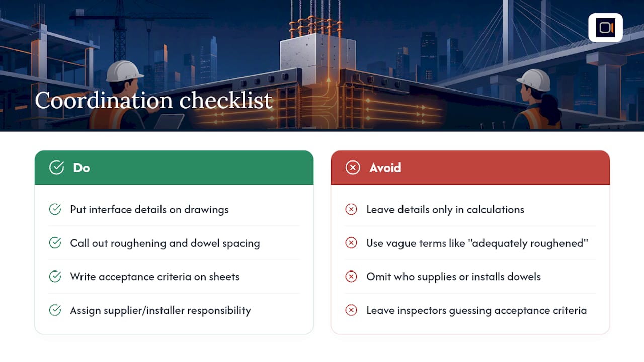
Document interface details explicitly in your drawings and specs, not just in the calculation package. Reviewers and inspectors need to see the roughening callout, the dowel spacing, and the acceptance criteria on the sheet itself.
Specify clearly who supplies and installs keys or dowels at each cold joint, and write the acceptance criteria into the specs so field crews and inspectors aren't left guessing what "adequately roughened" means.
A Practical Way to Organize Shear Transfer Checks
This section covers a tool, not a code requirement. You don't need software to understand shear transfer, but organizing the related calculations across a full project gets tedious fast when you're tracking wall lines, openings, hold-downs, and transfer straps by hand.

ShearWise Pro is built for exactly that coordination problem on 1-story and 2-story wood-framed projects: it organizes shear wall calculations, transfer strap forces, and story drift checks into a single workflow, then exports a clean, permit-ready shear wall report for review. If you're juggling multiple wall lines and full-height segments on a current project, start a free trial and generate your first three reports at no cost to see how the workflow fits your process.
Sources
- Shear transfer resistance with different interface conditions: Evaluation of design provisions and proposed equation (Appl. Sci., 2023)
- Hofbeck, Ibrahim & Mattock — Shear Transfer in Reinforced Concrete (ACI journal, 1969)