
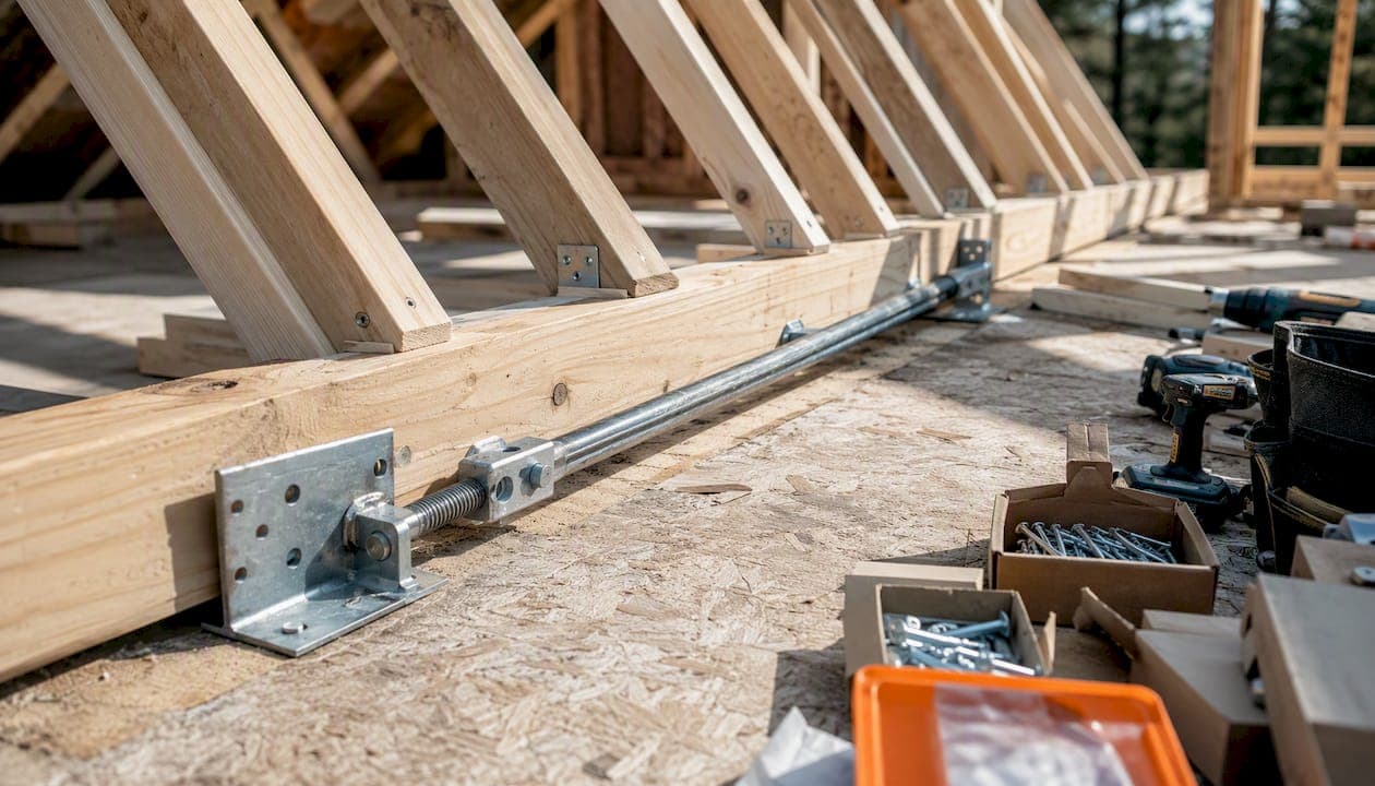
A drag strut, or collector, is a diaphragm boundary element that gathers shear from a diaphragm and transfers it into vertical lateral-force-resisting elements. The immediate design action is straightforward: determine the drag force in pounds per linear foot, define its extent and orientation on the framing plan, and identify every resisting location where that force gets picked up by a shear wall or braced frame. Every one of those items needs to appear on the contract documents, not just in your calculation package.
Before you go further into drag strut design, run this quick check on any project in front of you:
- Is there a continuous, unbroken load path from the diaphragm through the collector to a vertical resisting element?
- Are the resisting elements (shear walls, braced frames, or moment frames) clearly identified and located on the plan?
- Are the reactions at each end of the collector documented with values the truss manufacturer or fabricator can actually use?
If any of those three answers is no, stop and fix the load path before detailing connections. Everything else in this guide builds from that checklist.
Key Takeaways
Drag strut design succeeds when the collector delivers a documented, factored-or-nominal drag force in plf to a resisting element that a truss manufacturer can build to without guessing.
| Point | Details |
|---|---|
| Label every drag force | State plf, direction, and factored/nominal status directly on the framing plan, not just in calculations. |
| Align collectors with LFRS elements | Direct alignment above the shear wall or frame is more efficient than an offset arrangement. |
| Supply plf and reaction data upfront | Give the truss fabricator DF magnitude, resisting lengths, and bearing width before shop drawings start. |
| Verify shop notes against your math | Cross-check printed RL, R, and U reactions on truss drawings line by line before approval. |
| Cite governing codes on plans | Reference ASCE 7, IBC, and ANSI/TPI provisions used to derive each drag load combination. |
| Use ShearWise Pro for consistent data | Its shear wall reports keep hold-down forces and wall line data aligned with the drag reactions you hand off to fabricators. |
Table of Contents
- What Is Drag Strut Design and How Do Codes Define It?
- Where Drag Struts Show Up on Real Projects
- How Diaphragm Shear Becomes an Axial Force in the Strut
- Choosing the Right Drag Strut Material and Configuration
- Which Codes and Load Cases Govern Drag Strut Design?
- How to Calculate Drag Strut Loads Step by Step
- Worked Example: Sizing a Wood Drag Truss for a Roof Diaphragm
- Detailing the Connection From Collector to Shear Wall
- Coordinating Drag Loads With the Truss Manufacturer
- Common Drag Strut Design Mistakes and a Final Review Checklist
- What Practicing Engineers Get Wrong About Drag Strut Coordination
- How ShearWise Pro Supports Your Drag Strut Workflow
- Sources
What Is Drag Strut Design and How Do Codes Define It?
Drag strut design is the process of sizing and detailing a structural member that collects diaphragm shear along its length and delivers that force, in axial tension or compression, to a discrete point where a shear wall or frame can resist it. ASCE 7 defines this element as a collector, or diaphragm boundary element, and describes it as a member parallel to the applied lateral load that gathers diaphragm shear and channels it to vertical elements of the lateral-force-resisting system (LFRS). The term "drag strut" is the field and design nickname for the same element. Engineers, truss manufacturers, and contractors use both terms interchangeably, and you'll see both on plan sets and shop drawings.
The confusion usually starts when a third term enters the conversation: drag truss. A drag truss is simply a premanufactured, metal-plate-connected wood truss that has been designed to perform the collector function, typically because it also serves as a roof or floor truss. According to Structure magazine's coverage of drag trusses, these are engineered to collect and transfer diaphragm shear to vertical LFRS elements, and the design professional of record must hand the truss manufacturer the drag force magnitude, orientation, and resisting locations rather than assume the fabricator will infer them.
| Term | What it describes | What to call it on plans |
|---|---|---|
| Collector | Generic code term for any member (wood, steel, or concrete) that gathers diaphragm shear | "Collector" per ASCE 7/IBC terminology, useful on general notes |
| Drag strut | Common field term for the same function, often steel strap, angle, or continuous chord | "Drag strut" with force and extent noted directly on the framing plan |
| Drag truss | A manufactured truss (typically wood, metal-plate-connected) built to perform collector duty | Label as "drag truss" and flag it explicitly on the truss layout for the manufacturer |
A collector is a diaphragm boundary element parallel to the applied load, and its job is to gather shear and hand it off to the vertical resisting system below.
When you label a drag element on a framing plan or truss layout, don't just draw an arrow. State the drag force in plf, note the direction of load application, and identify the wall line or frame it ties into by grid reference. Truss manufacturers building drag trusses cannot guess your intent from a generic "collector" callout; they need a number.
Where Drag Struts Show Up on Real Projects
Drag struts aren't needed on every wall line. They become necessary wherever the diaphragm's shear flow gets interrupted or concentrated, and recognizing those conditions early saves a lot of redesign later.
- Roof or floor diaphragms with large openings (stairwells, skylights, mechanical shafts) that break the shear path and force a reroute around the opening.
- Re-entrant corners and L-shaped or offset floor plans, where the diaphragm geometry creates stress concentrations at the inside corner.
- Long shear wall lines where the diaphragm shear exceeds what a single segment of wall can absorb without a collector spreading the load.
- Discontinuous diaphragms, such as a diaphragm that steps in plan or elevation between stories.
- High-wind coastal zones and high-seismic regions, where diaphragm forces are large enough that even modest openings trigger a drag requirement.
- Large-span roof diaphragms over open floor plans, common in light commercial and multi-family wood construction.
Construction type changes the typical solution but not the underlying principle. Wood-framed buildings often use a drag truss or a continuous double top plate detailed as a chord. Steel-framed buildings frequently rely on a rolled shape or built-up angle bolted or welded into the framing, sized per AISC connection guidance. Concrete diaphragms use a reinforced beam or thickened slab edge as the collector. Even outside of buildings, the same axial transfer logic governs aircraft drag strut design, where landing gear structures use drag struts to carry axial loads under a very different but analogous set of load cases and certification requirements.
How Diaphragm Shear Becomes an Axial Force in the Strut
Picture a wind or seismic load hitting a roof diaphragm. That load doesn't disappear into the framing randomly. It generates shear that flows toward the diaphragm's boundary, gets picked up by chords running perpendicular to the load, and then needs a path down into the ground. The drag strut is the piece of that path that runs parallel to the load direction and collects shear from the diaphragm skin over its length, converting it into an axial force.
Trace the path like this: diaphragm sheathing transfers shear into the diaphragm boundary, the boundary member (often the same double top plate acting as both chord and collector, depending on load direction) picks up that shear as a distributed axial load, the drag strut or collector carries that axial force to a specific point, and finally the shear wall or braced frame below takes the concentrated reaction down to the foundation. Break any link in that chain and you get a local overstress or a diaphragm tear, even if every other member on the project is adequately sized.
- Diaphragm sheathing to boundary nailing undersized for the unit shear demand.
- A gap in the collector where a window or door header interrupts the continuous member without a designed splice.
- Misalignment between the collector's reaction point and the actual shear wall location, forcing an unplanned transfer that was never detailed.
Pro Tip: Trace the load path on the framing plan with a colored highlighter before you finalize connection sizes. If the highlighter line breaks anywhere, so does your load path, and no amount of connector capacity downstream fixes an interruption upstream. The most reliable arrangement, according to Structure magazine, is a drag strut aligned directly above the vertical LFRS element it feeds. Offset arrangements work, but they're less efficient and should be reserved for light shear demands or situations where alignment simply isn't possible given the architectural layout.
Choosing the Right Drag Strut Material and Configuration
Material selection for a drag strut comes down to load magnitude, span, constructability, and what the rest of the structure is already built from. Mixing materials unnecessarily adds connection complexity, so most engineers stay within the primary structural system unless loads demand otherwise.
- Continuous chord collector: typically a double top plate or ledger in wood construction, spliced with plywood or metal straps at breaks; economical for light to moderate drag loads.
- Steel strap or angle collectors: used when wood capacity runs out or when the collector needs to bridge a long opening; requires careful attention to bolt group capacity per AISC guidance.
- Multi-ply drag trusses: a manufactured wood truss reinforced with two or three plies, common in residential and light commercial roof framing where the truss already exists for gravity spanning.
- Cold-formed steel (CFS) members: appear in mid-rise wood-alternative or hybrid construction, useful where fire rating or dimensional stability matters more than raw cost.
- Reinforced concrete beams: standard for concrete diaphragm buildings, sized as part of the diaphragm edge detail rather than as a separate add-on member.
Treat these ranges as a starting sanity check, not a substitute for calculation. Cost and constructability comparisons between collectors and drag struts generally favor integrating the collector into existing diaphragm framing when loads allow it, reserving dedicated steel or multi-ply solutions for cases where the diaphragm framing genuinely can't carry the demand.
Which Codes and Load Cases Govern Drag Strut Design?
Every drag strut calculation traces back to a small set of governing documents, and knowing which one answers which question keeps your design defensible under review. ASCE 7 supplies the fundamental definition and the wind and seismic load combinations that generate the drag force in the first place. The International Building Code layers in the provisions that reference truss standards, diaphragm requirements, and the load-combination rules that determine whether live or snow loads need to be stacked with seismic drag cases. ANSI/TPI governs truss design and fabrication once the drag force reaches a manufactured truss, and APA publishes the nailing pattern and diaphragm shear tables that dictate fastening into wood chords.
The building designer's job is to hand off a number and a location. The truss manufacturer's job is to prove the truss can carry that number to that location. Neither step works without the other happening correctly first.
Run separate load cases for wind-dominated drag and seismic-dominated drag; they rarely govern identically, and in high-seismic regions the seismic case usually controls collector design even when wind governs the diaphragm shear itself. IBC's load-combination language determines whether you need to include snow or live load in combination with seismic, which matters most on long-span roof diaphragms carrying heavier snow loads.
- State on the plans whether drag forces are factored (strength-level) or nominal (allowable stress), since this single labeling choice changes every downstream calculation the truss manufacturer runs.
- Add a note specifying the applicable ASCE 7 load combination number used to derive the drag force, so reviewers and fabricators can trace your math without a phone call.
- Where wind and seismic both apply, show both drag values and flag which one governs at each resisting location.
How to Calculate Drag Strut Loads Step by Step
Sizing a collector is a conversion exercise more than anything else: you're translating a diaphragm shear demand into an axial force, then redistributing that axial force into concentrated reactions at your resisting walls. Here's the sequence that gets you there.
- Identify the tributary diaphragm area and unit shear. Establish which portion of the diaphragm drains into the collector line and compute the diaphragm's unit shear (plf) along that boundary using your governing wind or seismic case.
- Compute the total drag force (DF). Multiply the unit shear by the length of diaphragm feeding the collector, or sum the tributary reactions directly if you're working from a diaphragm shear diagram. Express this total in pounds or kips.
- Convert total DF into plf along the collector. Divide the total drag force by the collector's length to get a uniform plf demand along the member, assuming uniform diaphragm loading.
- Determine reaction locations and tributary widths at resisting elements. Identify each shear wall or frame segment the collector delivers force to, and calculate the concentrated plf or point reaction each one needs to resist based on its tributary length along the collector.
- Check axial capacity and fastening. Verify the member (chord, truss ply count, steel angle) has adequate axial capacity, and separately check that the nailing or bolting pattern can transfer the plf demand into and out of the member without exceeding allowable fastener spacing.
- Evaluate uplift and combined loading. Check whether the collector also participates in chord or uplift resistance under a different load direction, and confirm connections are checked for the governing combined case, not just the isolated drag case.
Once you've worked through that sequence, document these outputs for the truss manufacturer or fabricator:
- Total drag force (DF) magnitude, with units and factored/nominal designation clearly stated.
- Plf demand along the top chord or collector length.
- Reaction locations, expressed as distances along the collector from a reference point.
- Uplift reactions, if the drag member also resists overturning at that location.
Worked Example: Sizing a Wood Drag Truss for a Roof Diaphragm
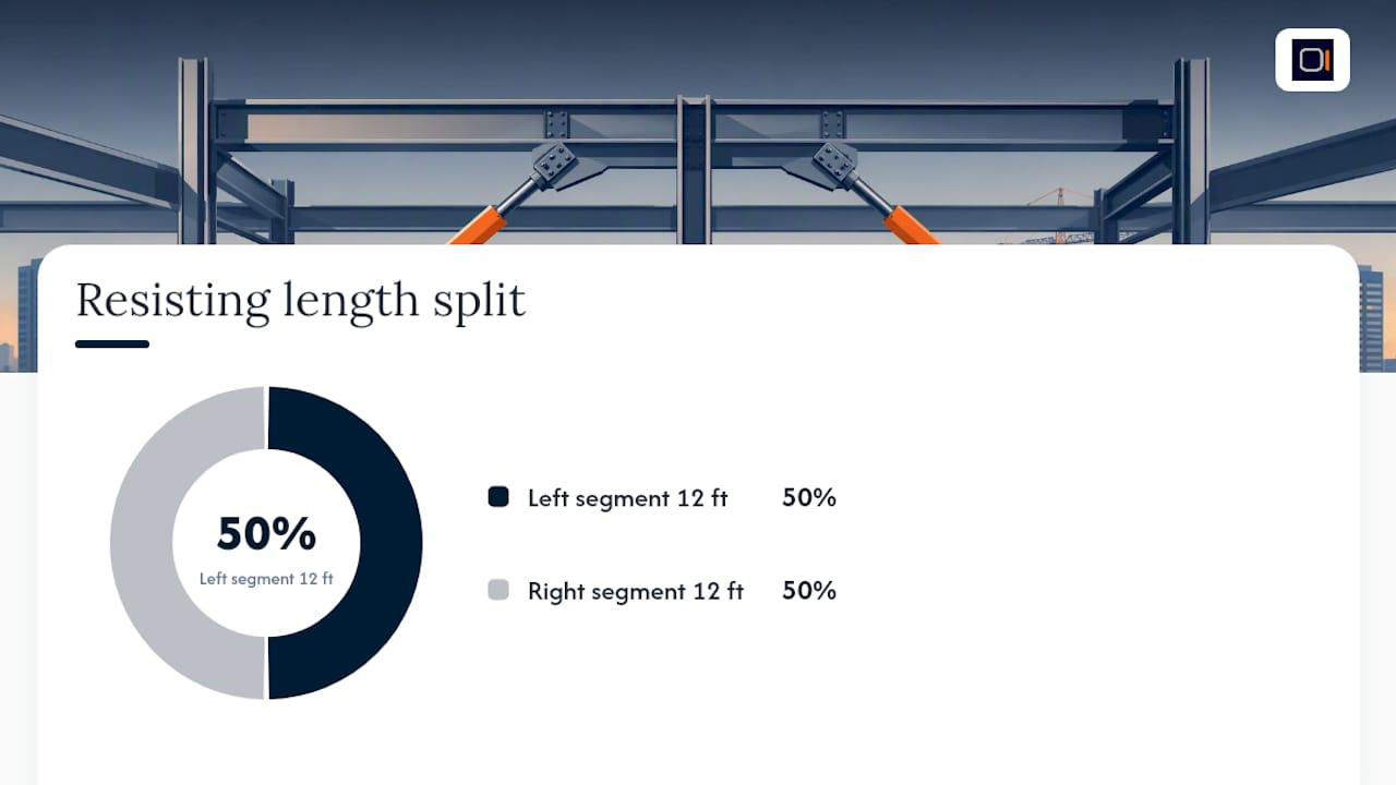
Numbers make this concrete. Consider a roof diaphragm delivering a total drag force of 5,000 lb into a drag truss spanning 24 feet, with two resisting shear wall segments at each end, each 12 feet long. This example follows the conversion approach shown in MiTek's technical note on drag loads, a standard reference for how truss design software converts drag inputs into shop drawing values.
Start with the total drag force of 5,000 lb spread uniformly across the top chord's 24-foot length. That works out to roughly 208.33 plf applied along the top chord, representing the diaphragm shear draining into the truss from above. That force then needs to exit the truss at the two resisting locations, each 12 feet long, along the bottom chord. Concentrating the 5,000 lb reaction over each 12-foot resisting segment yields approximately 416.67 plf resisted at the bottom chord over that width, essentially double the applied top chord rate, because the full force collected across 24 feet is being handed off through a 12-foot bearing zone.
| Parameter | Value |
|---|---|
| Total drag force (DF) | 5,000 lb |
| Top chord length | 24 ft |
| Applied plf on top chord | ~208.33 plf |
| Resisting wall segment length | 12 ft |
| Resisted plf at bottom chord | ~416.67 plf |
The MiTek workflow typically doubles the drag case for left and right resisting directions, since wind and seismic can act in either orientation. Your shop drawing note should give the manufacturer:
- The applied top chord plf (208.33 plf in this case) and its direction of application.
- The resisted bottom chord plf (416.67 plf) at each defined bearing zone.
- Reaction notations the manufacturer prints back for verification, commonly labeled RL (reaction left), R (reaction right), and U (uplift).
- Whether the 5,000 lb figure is factored or allowable stress design (ASD) level, so the truss software applies the correct combination.
A sample spec note might read: "Drag truss designed for total drag force of 5,000 lb (ASD), applied as 208 plf over 24' top chord, resisted as 416 plf over 12' bearing zones at each end. Provide RL, R, and U reactions on shop drawings for review." That single sentence, placed directly on the truss layout, removes almost every ambiguity a fabricator would otherwise have to guess at.
Detailing the Connection From Collector to Shear Wall
A perfectly sized drag strut is worthless if the connection at each end can't deliver the same force into the shear wall. Construction documents need to show the connector type and size, fastener spacing and edge distances, and how the connector plate or clip relates to the truss plate locations so the fabricator doesn't inadvertently place a plate where your strap needs to sit.
- Show the strap tie, shear angle, or bolted connection type explicitly at each reaction point, including manufacturer part number where applicable.
- Note fastener spacing and required edge/end distances so field crews aren't guessing at minimum spacing under APA nailing tables.
- Coordinate hold-down locations with the collector reaction points; a hold-down sized for uplift alone won't necessarily handle the combined uplift-plus-drag condition at that same post.
- Specify corrosion protection (galvanized, stainless, or coated hardware) where the connection is exposed to weather or treated lumber.
- Flag inspection access requirements on the drawings so special inspectors know exactly which connections require verification before cover-up.
Strap ties and shear angles are the two most common hardware choices at these transfer points, and getting the transfer strap sizing right depends heavily on matching the fastener count to the calculated plf, a topic covered in more depth in this guide to strap ties in shear design. Hold-down rods deserve their own coordination check too, especially on two-story buildings where uplift accumulates through multiple levels; see this breakdown of hold-down rod behavior in multi-story wood buildings for the interaction between overturning and drag demands at the same connection.
- Connection checklist: connector type and part number, fastener pattern and spacing, edge distances, hold-down alignment, corrosion protection, and inspection callouts.
Coordinating Drag Loads With the Truss Manufacturer
Drag strut design almost always splits responsibility between the registered design professional and the delegated truss manufacturer, and confusion about who owns which piece is one of the most common sources of rework. The design professional determines the drag force, its location, and its extent. The truss manufacturer (or fabricator) takes that information and produces a truss design and shop drawings that physically deliver it, including ply count, plate sizing, and printed reactions.

| Responsibility | Registered design professional | Truss manufacturer / fabricator |
|---|---|---|
| Determine drag force magnitude and units | Yes | No |
| Establish resisting locations and lengths | Yes | No |
| Size truss plies and connector plates | No (reviews only) | Yes |
| Print reaction values (RL, R, U) on shop drawings | No | Yes |
| Verify shop drawings match design intent | Yes (final check) | Provides drawings for review |
The information packet you send to the manufacturer should include the DF magnitude with its factored or nominal designation, the resisting locations with lengths, required bearing width, and any connection requirements tied to specific hardware you've already selected. Skipping any one of these forces the manufacturer to make an assumption, and assumptions on drag loads have a way of becoming expensive change orders.
- Send: DF magnitude (with ASD/LRFD designation), resisting location lengths, bearing width, minimum ply count if predetermined, and connection hardware requirements.
Pro Tip: Before stamping approval on truss shop drawings, cross-check the printed reactions against your own calculated plf values line by line. A mismatch usually means someone applied the wrong load combination on the software side, not that your original numbers were wrong.
Common Drag Strut Design Mistakes and a Final Review Checklist
Most drag strut failures in review trace back to a handful of repeat offenders. Unlabeled drag forces top the list: a plan that shows a collector line with no plf value or reaction data forces the fabricator to guess. Insufficient nailing or fastening comes next, often because someone verified axial capacity but never checked whether the fastener pattern could actually transfer that plf into the member. Misaligned drag-to-shear-wall layouts show up when architectural changes shift a wall after the structural drawings are already drafted. Ignoring uplift or combined loading happens when a collector also carries chord or overturning duty and only one load case gets checked. And single-ply chords are sometimes assumed adequate based on axial capacity alone, without verifying whether the required nail spacing actually fits on a single member.
Run this checklist before releasing drawings for construction:
- Is the drag force labeled in plf, with factored/nominal status stated, at every collector location?
- Are resisting wall or frame locations identified by grid line and length?
- Does the collector align directly above its resisting element, or is an offset explicitly justified?
- Have ply count, species, and minimum size been specified rather than left to the fabricator?
- Is the nailing or fastening pattern checked against the plf demand, not just against axial capacity?
- Are hold-downs at collector reaction points sized for the combined uplift-plus-drag condition?
- Are corrosion protection requirements noted for exposed hardware?
- Do truss shop drawing reactions (RL, R, U) match your calculated values?
- Are inspection triggers called out for special inspection of critical connections?
- Is the governing load combination (wind vs. seismic) documented for each collector segment?
Three red flags deserve an immediate stop-and-recheck: a collector with no printed force value, a shop drawing reaction that doesn't match your calculation within a reasonable tolerance, and any drag element that changes direction or splices without a detailed connection shown. Pro Tip: Require the truss manufacturer to print the applied drag load case number directly on the shop drawing, not just the resulting reactions. That single addition makes your review five minutes instead of fifty.
What Practicing Engineers Get Wrong About Drag Strut Coordination
The technical math behind drag strut design is genuinely not the hard part. Diaphragm shear, axial conversion, plf distribution: these are first-year structural concepts dressed up in project-specific numbers. What actually causes schedule delays and RFIs is coordination friction between the design professional and the delegated truss designer, and most engineers underestimate how much of that friction is preventable with better plan notes.
The recurring surprise on site is almost never a calculation error. It's a truss shop drawing that shows a reaction value nobody on the design team expected, because the drag load case got applied in a direction the software defaulted to rather than the direction the engineer intended. MiTek's own documentation makes clear that software typically doubles a drag case left and right automatically. If your plan note doesn't specify which direction actually governs, you'll get a truss designed for the worse of two cases, sometimes oversized, sometimes misaligned with what your shear wall schedule assumed.
My practical advice at pre-construction: get the truss manufacturer's drag load submittal in hand before you finalize your hold-down schedule, not after. Cross-check every printed RL, R, and U value against your own hand calculation, even on repeat project types where the numbers "always look about right." And above everything else, write down whether your drag force is factored or nominal on every single plan sheet where it appears. That one habit, more than any formula in this guide, is what separates a clean truss submittal review from a three-round back-and-forth with the fabricator.
How ShearWise Pro Supports Your Drag Strut Workflow
ShearWise Pro won't calculate your drag truss loads for you, but it solves the adjacent problem that makes drag strut coordination messy in the first place: keeping your shear wall lines, hold-down forces, and transfer strap data organized in one place instead of scattered across spreadsheets and hand notes.

For 1-story and 2-story wood-framed projects, ShearWise Pro documents wall lines, openings, full-height shear segments, and hold-down forces, then exports a clean PDF report you can hand straight to a truss manufacturer alongside your drag force data. Since the resisting locations for your drag struts are the same shear wall segments you're already calculating in ShearWise Pro, the reaction values, wall lengths, and hold-down forces line up automatically instead of requiring a second manual cross-check between two disconnected files. That consistency is exactly what your information packet to the fabricator needs: reaction locations and forces that match your shear wall design one-to-one, not approximated after the fact. If you want to see how the reports look before committing, the ShearWise Pro shear wall calculator offers a free trial with three watermarked reports, and you can sign up to try it on your next project.
Sources
- Drag Trusses
- ASCE 7
- IBC 2021 (online content)
- Design and Analysis of Drag Strut in Passenger Aircraft