

Oregon building codes regulate lateral design through two primary codes: the Oregon Structural Specialty Code (OSSC) for commercial and engineered residential construction, and the Oregon Residential Specialty Code (ORSC) for typical 1- and 2-family dwellings. A third code, the Oregon Existing Building Code (OEBC), governs retrofit requirements when existing buildings change occupancy or undergo significant modification. Together, these three codes define every lateral design obligation you will encounter on Oregon projects.
The core distinction is straightforward. ORSC offers a prescriptive path with pre-defined bracing tables and panel lengths. OSSC requires engineered calculations, licensed design professionals, and full documentation of load transfer. Most of Portland and western Oregon falls under Seismic Design Category D, which tightens requirements under both codes and eliminates many of the relaxed allowances available in lower seismic zones.
Key elements governed by both codes include:
- Shear walls and braced wall panels as the primary lateral force-resisting elements
- Diaphragms at roof and floor levels that collect and transfer lateral forces
- Hold-down anchors and tie-down hardware to prevent wall overturning
- Continuous load paths from roof to foundation, with detailed connections at every transfer point
- Seismic design parameters (Ss, S1, and seismic design category) that drive panel length and detailing requirements
What are the core seismic and structural requirements in Oregon building codes?
Oregon's lateral design requirements are built around seismic performance, and the OSSC adopts ASCE 7-16 as its primary load standard. Oregon-specific amendments go further than the national model code, adding tsunami load analysis, breakaway wall design, and foundation scour resistance for coastal projects. These state-level additions apply to any structure in a designated tsunami inundation zone and are not optional.
Seismic design categories
Seismic Design Categories (SDC) range from A through F, with higher letters representing greater seismic hazard. All locations within or administered by the City of Portland are classified as SDC D under the OSSC. SDC D triggers the most demanding lateral detailing requirements for wood-framed buildings, including hold-down devices at braced wall panel ends, specific nailing schedules, and restrictions on panel placement near building corners.

Load combinations and lateral force-resisting elements
OSSC Chapter 16 governs the design loads you must combine for lateral analysis. Wind and seismic forces are treated as separate load cases, and the more demanding result governs. The lateral force-resisting system for most wood buildings consists of three components working together:
| Element | Function | Key Code Reference |
|---|---|---|
| Shear walls / braced wall panels | Resist in-plane lateral forces | OSSC / ORSC R602.10 |
| Roof and floor diaphragms | Collect and distribute lateral forces to walls | ASCE 7-16 / OSSC |
| Hold-downs and tie-down anchors | Prevent overturning of shear wall segments | ORSC R602.10 |
| Chord splices and collectors | Transfer diaphragm edge forces into walls | OSSC engineered design |
| Foundation connections | Transfer wall forces into the ground | OSSC / ORSC foundation chapters |
Tsunami and flood zone implications
For coastal Oregon projects, OSSC adopts ASCE 7-16 Chapter 6 with state amendments requiring tsunami load analysis. Breakaway wall design, foundation scour resistance, and hydrostatic load combinations are mandatory in tsunami inundation zones. This is a critical differentiation from the International Building Code baseline that many engineers trained outside Oregon may not anticipate.
How do prescriptive and engineered lateral design paths differ under ORSC and OSSC?
The prescriptive path under ORSC Section R602.10 is a table-driven method. You select a bracing method, look up minimum panel lengths based on seismic design category and wall line spacing, apply adjustment factors, and confirm your layout meets the minimums. Braced wall line spacing must not exceed 25 feet on center in SDC D, with one exception: a single room of limited size may have a maximum wall line spacing exceeding the typical limit. The minimum total bracing per wall line after all adjustment factors is maintained at a standard minimum length.
Prescriptive design applies when all of the following conditions are met:
- The structure is a 1- or 2-family dwelling covered under ORSC
- Building height does not exceed typical low-rise limits
- Wall height does not exceed typical single-story limits
- Seismic exposure is SDC D1 or lower with minimum 4-foot panel widths before adjustments
- Wind exposure is Category B
When any of those conditions fall outside the table limits, or when the project is commercial, multi-family, or otherwise non-residential, engineered design under OSSC is required. A licensed design professional must prepare calculations and drawings demonstrating load transfer, seismic force resistance, and full structural detailing.
Common misconceptions about prescriptive bracing
Several misunderstandings come up repeatedly in Oregon plan reviews:
- Prescriptive does not mean no documentation. Plan submittals must still show braced wall line locations, panel lengths, bracing methods, and hardware types.
- Jurisdictions can restrict prescriptive allowances. Local jurisdictions in Oregon may require engineered designs even for buildings that nominally fall within ORSC prescriptive limits, particularly in high seismic zones.
- Minor additions may qualify for reduced lateral requirements. Portland's guidance on minor additions and dormers defines specific size and configuration criteria under which lateral calculations are not required. Additions exceeding those criteria must upgrade the existing lateral system to current code.
Pro Tip: Before assuming prescriptive compliance, confirm with the local jurisdiction whether any overlay amendments restrict ORSC allowances in your specific SDC D subzone. Portland, Eugene, and other Oregon cities have issued local guidance that narrows the prescriptive window.
What triggers seismic retrofits and special inspections under OEBC and OSSC?
Seismic retrofits under the OEBC are triggered by specific events, not just by age or condition. The most common trigger is a change of occupancy in an unreinforced masonry (URM) building. Under OEBC, that occupancy change mandates a seismic retrofit to meet current OSSC standards, including upgrades to the lateral force-resisting system and wall-to-diaphragm anchorage.
Portland City Code Chapter 24.85 adds local triggers beyond the state OEBC requirements. Engineers working on Portland projects should check Chapter 24.85 early in the design process, since it can require seismic upgrades for alterations that would not trigger retrofit obligations under the state code alone.
Common retrofit triggers checklist
- Change of occupancy in a URM building
- Additions exceeding the minor addition criteria defined in Portland's lateral bracing guidance
- Structural alterations that increase loads on the existing lateral system
- Projects subject to Portland City Code Chapter 24.85 thresholds
- Phased seismic upgrade programs for high-risk building categories
Special inspection requirements
OSSC requires special inspections for seismic-related elements in SDC C and higher. For SDC D projects, the following components typically require documented special inspection:
- High-load diaphragm nailing (when nailing schedules exceed standard prescriptive values)
- Shear wall sheathing installation, including nail size, spacing, and edge distance
- Hold-down anchor installation and torque verification
- Anchor bolt placement in concrete or masonry foundations
- Structural welding on lateral force-resisting connections
- Masonry construction used as part of the lateral system
Special inspections must be documented by a qualified inspector and submitted to the building department. Missing or incomplete inspection records are one of the most frequent causes of permit closeout delays on Oregon projects.
Additional Oregon code considerations for residential lateral design
Joist and rafter notching limits
Notching joists and rafters to accommodate mechanical, electrical, or plumbing runs can weaken the diaphragm if done incorrectly. Oregon code limits on notching and wall penetrations must be followed carefully to maintain lateral force resistance in floors and roofs. Cuts that exceed code limits in a diaphragm chord or collector zone can invalidate the lateral design for that floor level.
Retaining walls and lateral soil loads
Retaining wall design in Oregon carries specific lateral load defaults. Portland's OSSC guidance sets the default lateral soil load at 40 psf per foot of depth for laterally unrestrained retaining walls and 60 psf per foot for laterally restrained walls. Walls supporting sloping backfill or surcharge loads require a geotechnical report. Basement and retaining wall designs must also account for lateral soil loads from earthquake motions, which adds a seismic component to what might otherwise seem like a purely gravity-driven element.
When you need a licensed structural engineer
Oregon law is specific about this. Registered structural engineers or registered architects qualified in structural work are the only professionals permitted to prepare drawings and calculations for the primary lateral force-resisting system of significant structures. Significant structures include hazardous facilities, essential facilities over 4,000 square feet or 20 feet in height, buildings with irregular features, and buildings more than four stories or 45 feet above average ground level. For non-exempt buildings, all construction documents must be stamped and signed by the registered professional.
Documentation and submittal requirements
Plan submittals for lateral design must include the following to pass Oregon jurisdiction plan review:
- Braced wall line locations and panel lengths shown on the floor plan
- Bracing method identified (segmental, continuous sheathing, portal frame, etc.)
- Hardware and hold-down types called out with manufacturer model numbers
- Engineered calculations for any element outside prescriptive limits
- Diaphragm connection details at roof, floor, and foundation levels
- For permit approval, framing members, header and beam sizes, and shear wall locations must all be clearly coordinated
Submittals that omit any of these items typically come back with correction notices, adding weeks to the review cycle.
How do you verify a continuous lateral load path in Oregon building design?
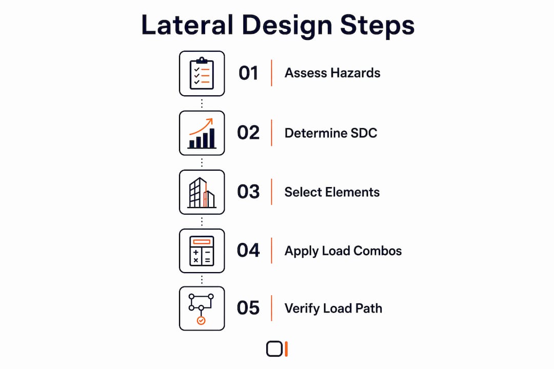
A continuous load path is the single most critical concept in lateral design, and it is also the most frequently incomplete element in submitted drawings. Lateral loads transfer from the roof diaphragm through shear walls and floor diaphragms down to the foundation, with every connection along that path needing to be explicitly detailed and sized. A shear wall with correct panel length and nailing schedule fails to perform if the diaphragm-to-wall connection above it is undersized or missing from the drawings.
Step-by-step load path verification
Follow this sequence on every project to confirm the load path is complete:
- Start at the roof. Identify the roof diaphragm boundaries, chord members, and collector elements. Confirm that diaphragm-to-wall connections (framing anchors, blocking, nailing) are detailed.
- Trace forces into the shear walls. Verify that the top plate connection transfers diaphragm shear into each shear wall. Check that wall sheathing, nailing schedule, and panel dimensions match the design.
- Check the hold-downs. Hold-down devices at wall ends must be sized for the calculated uplift force and connected to both the stud framing above and the foundation or floor framing below.
- Move to the floor diaphragm. Repeat the diaphragm boundary check at each floor level, confirming chord splices and collector connections are shown.
- Verify the foundation connection. Anchor bolts, sill plate hardware, and foundation dimensions must be consistent with the lateral forces calculated at the base of each shear wall.
- Check for discontinuities. Shear walls on upper floors must align with walls below, or transfer elements (drag struts, collectors) must be designed to redirect the force. Stacked wall lines are the cleanest solution in SDC D.
Common load path errors
- Diaphragm chord members not identified or sized
- Hold-down forces not carried through floor framing to the foundation
- Shear wall locations on architectural plans that conflict with structural plans
- Collector elements missing at re-entrant corners or offsets
Architectural features like large window openings and open floor plans frequently conflict with shear wall placement. Late-stage changes to wall locations or window sizes can invalidate the lateral design entirely, particularly in SDC D where panel placement near building corners is tightly controlled. Coordinating architectural and structural plans early in schematic design prevents those conflicts from becoming permit-stage problems.
Pro Tip: Use a wall line analysis diagram on your structural drawings that explicitly labels each wall line, its total bracing length, and the governing load case. Reviewers can verify compliance at a glance, and you eliminate the most common source of correction notices.
Organize your lateral design with ShearWise Pro

Tracking wall lines, panel lengths, hold-down forces, and load path documentation across a multi-story wood project is where errors accumulate. ShearWise Pro is built specifically for 1-story and 2-story wood-framed buildings, helping engineers, architects, and designers organize shear wall calculations, full-height segments, transfer straps, and story drift checks in one place. The platform generates clean PDF reports formatted for permit submittal and plan review coordination.
If you are working on Oregon residential or light commercial projects and want to cut the time spent organizing lateral calculations, try ShearWise Pro and see how the workflow fits your practice.
Key Takeaways
Oregon lateral design under OSSC and ORSC requires a documented continuous load path, correct seismic design category assignment, and full submittal documentation to achieve permit approval in SDC D jurisdictions.
| Point | Details |
|---|---|
| Two code paths govern lateral design | ORSC prescriptive applies to 1- and 2-family dwellings; OSSC engineered design applies to commercial and complex residential projects. |
| SDC D covers most of Portland | All Portland locations are classified as Seismic Design Category D, requiring hold-downs at wall ends and strict panel placement near corners. |
| Braced wall line spacing limit | Maximum 25 feet on center in SDC D, with a single-room exception allowing increased spacing for small rooms. |
| OEBC triggers retrofits on occupancy change | A change of occupancy in an unreinforced masonry building mandates a seismic retrofit to current OSSC standards, including wall-to-diaphragm anchorage upgrades. |
| Load path documentation is mandatory | Plan submittals must show braced wall lines, panel lengths, hardware types, and diaphragm connections; incomplete submittals generate correction notices and delay permits. |