
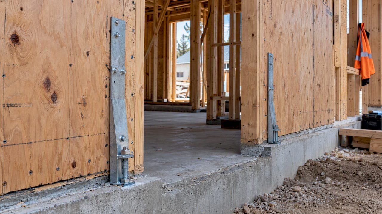
The segmented shear wall method treats each full-height, fully sheathed panel between openings as an independent shear element and sums their capacities to find total wall line resistance. We recommend it when openings cleanly divide a wall into discrete, fully sheathed segments and the design can accommodate a hold-down at every segment edge. It tends to run conservative compared to other methods, which makes it a dependable first choice for straightforward residential layouts.
TL;DR:
- The segmented shear wall method is conservative and best suited for walls with full-height, fully sheathed panels separated by clean openings and where hold-downs at each segment edge are feasible.
- Its capacity calculation relies on selecting a unit shear value from SDPWS tables, adjusting for aspect ratios, and summing the shear capacities of all fully sheathed segments.
- More hold-downs and detailed load path checks increase the cost but improve predictability, making it ideal for straightforward residential layouts.
- The method is not appropriate when a wall lacks clean full-height segments, or when hardware conflicts or budget limitations prevent multiple hold-downs.
- Software like ShearWise Pro streamlines segment input, calculations, and reporting, reducing errors and saving time for engineers.
Table of Contents
- Overview and formal definition of the segmented shear wall method
- When to use segmented method vs alternatives
- Step-by-step calculation procedure for the segmented shear wall method
- Concise worked example applying the segmented method
- Segmented vs perforated vs Ni-Karacabeyli: what changes in capacity and detailing
- Design details and practical detailing notes
- How load transfers through a segmented shear wall
- Common failure modes and how the method addresses them
- Balancing conservatism and economy in practice
- ShearWise Pro: built for the segmented workflow
- FAQ
- Sources
Overview and formal definition of the segmented shear wall method
The segmented method only counts fully sheathed, full-height wall segments as resisting elements. Sheathing above or below window and door openings is ignored entirely, even when it is structurally attached, because the method assumes those short pieces contribute negligible stiffness compared to the full-height segments.

The governing equation is simple: each segment's shear capacity, Vi, equals its unit shear capacity, vi, multiplied by its length, li. Total wall line capacity is the sum of all segment capacities, Vwall = Σ Vi. Unit shear values come from tables in the ANSI/AWC 2021 SDPWS, which also sets the aspect ratio adjustments and governing assumptions that keep the method valid.
There are limits. Each segment has a maximum unit shear capacity tied to sheathing type, thickness, and nailing schedule, and segments that fall outside allowable aspect ratios need adjustment factors before their capacity counts toward the total. Our guide to full-height segment design walks through segment sizing in more detail.
When to use segmented method vs alternatives
Choosing between segmented, perforated, and mechanics-based methods comes down to how much restraint the design can tolerate and how much the architecture cooperates.
- Segmented fits walls with large openings that leave clear, full-height sheathed panels and a layout that can accept multiple hold-downs.
- Perforated fits walls with smaller, more frequent openings where full restraint at every segment is impractical or costly, since it only requires hold-downs at the wall ends.
- Mechanics-based or force-transfer methods fit complex layouts with narrow piers, irregular openings, or where reducing hardware count matters more than calculation simplicity.
Segmented designs typically mean more hold-downs, more chord forces to resolve, and more anchorage points to detail and inspect. That cost buys predictability: the AWC FAQ comparing the two methods confirms segmented requires hold-downs at each full-height segment edge, while perforated needs them only at end posts. Segmented becomes inappropriate when a wall has no clean full-height segments, when hold-down hardware would conflict with architectural finishes, or when the project budget cannot absorb the added hardware and labor.
Step-by-step calculation procedure for the segmented shear wall method
A segmented calculation follows a fixed sequence, and keeping the inputs organized up front saves rework later.
- Gather inputs: wall line length, segment lengths and locations, applied lateral load (wind or seismic), sheathing type and thickness, nailing schedule, and framing species typically pulled from project drawings and SDPWS tables.
- Select unit shear (v) for each segment from the applicable SDPWS table based on sheathing, fastener schedule, and framing.
- Apply adjustments for aspect ratio when a segment's height-to-width ratio falls outside the standard range, along with any species or specific gravity factors.
- Calculate per-segment shear, Vi = vi × li, for every qualifying segment.
- Check hold-down (uplift) reactions at each segment edge using the overturning moment and segment geometry.
- Sum segment resistances, Vwall = Σ Vi, and compare against demand.
- Verify drift where required, since segmented walls with many narrow segments can govern on deflection before strength.
Pro Tip: Table your segment lengths, selected v values, and hold-down reactions in one place before summing; it is the fastest way to catch a mismatched unit shear or a missed aspect ratio adjustment before it reaches a reviewer.
For documentation, keep the per-segment breakdown visible in your final report rather than only the summed total. Reviewers checking against HUD's Appendix E worked example expect to see each Vi traced back to its segment length and selected unit shear, not a single aggregated number.
Concise worked example applying the segmented method
Consider a wall line with two full-height segments, moderate in length, sheathed with 15/32-inch wood structural panels on one side, 8d common nails at 4 inches on center at panel edges. Say the applied seismic demand on the wall line is a representative design load (example only).
Following HUD Appendix E's worked procedure, we select a unit shear value for the sheathing and nailing schedule, then calculate each segment's shear and sum them:
Summed resistance exceeds the applied load demand, so the wall line passes under ASD. The hold-down at each segment edge is then sized from the overturning moment at that segment, not the wall line as a whole, which is the detail that most often trips up engineers new to the method. This structure mirrors the layout in our calculation examples piece, which walks through two full numeric cases without skipping steps.
Segmented vs perforated vs Ni-Karacabeyli: what changes in capacity and detailing
These three approaches differ mainly in how they treat openings and end restraint, and that difference shows up directly in both predicted capacity and detailing scope.
- Segmented ignores sheathing above and below openings entirely, which produces conservative capacity but requires hold-downs at every segment edge.
- Perforated accounts for the full wall length including sheathing around openings, needing restraint only at the wall ends, which HUD and FEMA testing shows is often conservative relative to fully restrained segmented predictions.
- Mechanics-based methods (including approaches building on Ni-Karacabeyli research) model pier behavior more precisely but demand more calculation effort and engineering judgment.
Detailing consequences follow directly: more segments mean more hold-downs, more chord force paths to resolve, and more anchorage points to inspect. Monotonic and cyclic test data confirms that added overturning restraint increases both capacity and stiffness, which is exactly the trade segmented designs make.
Design details and practical detailing notes
A few detailing checks catch most of the errors we see before documents go out for permit.
Hold-down capacity must match the calculated uplift reaction at each segment, with anchor bolt spacing and embedment checked against the manufacturer's listed values, not assumed. Aspect ratio limits from SDPWS and its Appendix B govern when a segment's height-to-width ratio requires a reduction factor; skipping this check is one of the most common sources of over-reported capacity. Nailing schedule, sheathing thickness, and stud spacing all tie directly back to the unit shear value selected in step two, so a change to any one of them means re-selecting v, not adjusting the final number after the fact. When hold-down hardware intersects finish work or framing coordination, loop in your contractor early. Partners like A to Z Construction handle structural remodeling coordination where hold-down placement affects existing framing.
How load transfers through a segmented shear wall
Lateral load enters the wall line through the diaphragm above, distributing to each full-height segment in proportion to its stiffness, which under the segmented method is assumed proportional to its length. Each segment then resists that load through shear in the sheathing, transferred into the framing through the nailing pattern along panel edges.
At the base of each segment, the resisting couple created by the applied shear and the segment's height generates an overturning moment. That moment produces tension on one edge of the segment and compression on the other. The tension side requires a hold-down anchored into the foundation or the framing below, while the compression side relies on the end stud (or built-up post) bearing directly onto the framing beneath it.

Chord forces develop along the top and bottom of each segment, requiring a continuous load path from the roof or floor diaphragm through the top plate, down through the sheathed segment, and into the foundation. Any break in that path (a missing strap, an undersized post, an anchor bolt that misses the required embedment) interrupts the mechanism the whole calculation assumes. This is why segmented design output needs to show not just the summed capacity but the discrete path for each segment's hold-down and chord connection, since a reviewer checking the calculation is really checking that the load path is complete at every segment.
Common failure modes and how the method addresses them
The dominant failure mode in a segmented shear wall is hold-down anchorage failure: the tension connection pulls out of the foundation or the framing before the sheathing reaches its rated capacity. The method addresses this directly by requiring a hold-down sized to the calculated uplift reaction at every segment edge, rather than relying on dead load or nailing alone to resist overturning.
A second common mode is nail fastener failure at panel edges, typically from under-driven or overdriven nails that reduce effective shear transfer. Selecting unit shear values tied to a specific, correctly installed nailing schedule is the method's built-in protection, but it only works if field installation matches the schedule assumed in the calculation.
Aspect ratio-related instability shows up in narrow, tall segments where the sheathing can buckle or rack excessively before reaching its rated unit shear. SDPWS aspect ratio adjustment factors reduce the allowable capacity for these segments, which is the method's way of penalizing geometry that is prone to this failure mode. Finally, chord failure from an incomplete load path at the top or bottom of a segment is addressed by requiring continuous strapping or blocking, a detail that is easy to miss on drawings but critical to the mechanism the calculation assumes.
Balancing conservatism and economy in practice
Segmented design speeds permit review on straightforward layouts. On tighter budgets or hardware-constrained walls, investing in perforated or mechanics-based analysis often reduces hold-down count meaningfully. Always document your assumptions and table your inputs.
— Evalin
ShearWise Pro: built for the segmented workflow
We built our platform around exactly this workflow: segment lengths, hold-down forces, transfer straps, and story drift checks organized in one place, exported as a clean PDF report ready for reviewer coordination. For engineers tired of rebuilding the same spreadsheet on every project, that organization alone cuts down on the manual aggregation errors that slip into segment summations under deadline pressure.

- Try it with the Three-Report Trial, three watermarked reports at no cost.
- Move to paid plans once you are ready for ongoing projects; current prices are on the pricing page.
- Our tutorials walk through segment setup and report generation step by step.
Start your trial or see the full feature set on our shear wall design program page.
FAQ
What is the segmented shear wall method?
The segmented shear wall method treats each full-height, fully sheathed wall panel between openings as a separate resisting element, with capacity calculated as unit shear times segment length. Sheathing above and below openings is excluded, and hold-downs are required at every segment edge, per the ANSI/AWC SDPWS.
How do you calculate segment shear capacity?
Segment shear capacity, Vi, equals the unit shear value, vi, selected from SDPWS tables, multiplied by the segment's length, li. Total wall line capacity is the sum of all segment values, as demonstrated in HUD's Appendix E worked example.
What is the difference between segmented and perforated shear wall methods?
The segmented method requires a hold-down at every full-height segment edge, while the perforated method only requires hold-downs at the end posts of the wall line, according to the American Wood Council. Perforated also accounts for sheathing around openings, which segmented ignores.
When should I avoid the segmented method?
Avoid segmented design when a wall lacks clean full-height segments, when hardware for multiple hold-downs would conflict with architectural finishes, or when the added anchorage cost outweighs the benefit of a simpler calculation. Perforated or mechanics-based methods often fit these cases better.
Can software help with segmented shear wall calculations?
Yes, a focused calculator can organize segment inputs, unit shear selection, hold-down forces, and summation automatically, reducing manual tracking errors. Our software supports this workflow for 1- and 2-story wood-framed projects, generating reviewer-ready PDF reports from the same inputs engineers already calculate by hand.
Sources
This guide draws on the ANSI/AWC SDPWS for governing provisions, HUD's Appendix E for the worked calculation sequence, and FEMA-sponsored test reports for empirical validation of restraint effects. We write these guides to reflect how working engineers actually calculate, not how a textbook simplifies the process. ShearWise Pro organizes the same segment, hold-down, and transfer strap inputs this workflow requires, producing reviewer-ready PDF output for 1- and 2-story wood buildings.