
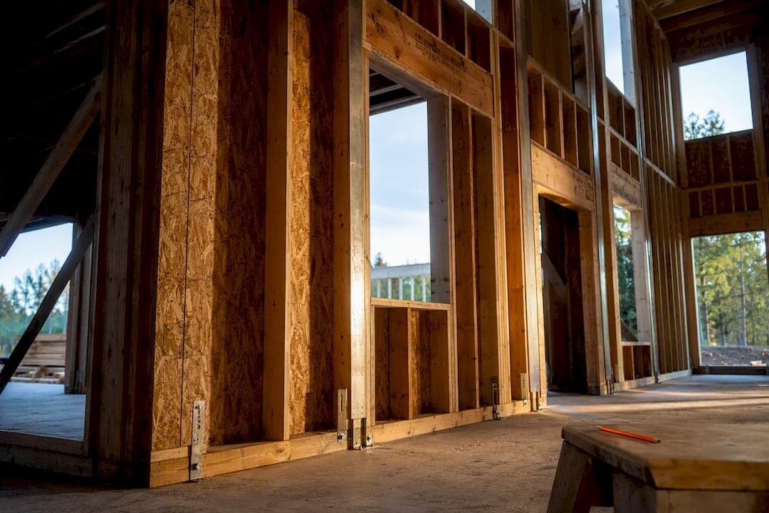
Three methods satisfy code for wood shear wall design: segmented (SSW), perforated (PSW), and force transfer around openings (FTAO). Choose perforated when you have extensive wood structural panel sheathing and want fewer hold-downs, segmented when openings isolate clean full-height segments, and FTAO when straps and collectors are the more practical route around a large opening, depending on project specifics. All three trace back to the AWC Special Design Provisions for Wind and Seismic (SDPWS), the Wood Frame Construction Manual (WFCM), and the IBC.
TL;DR:
- Perforated shear walls typically require fewer hold-downs, reducing hardware costs and inspection points compared to segmented walls, especially on longer wall lines.
- The maximum aspect ratio of full-height shear wall segments is approximately 3.5 to 1; exceeding this ratio can lower capacity or require special analysis.
- Calculating Vwall involves using tabulated unit shear values (ν), the shear capacity adjustment factor (Co), and the summed full-height sheathing length, with proper load path verification.
- Seismic design demands tighter nailing schedules, more conservative connections, and can favor perforated or segmented methods over FTAO for cyclic load performance.
- Using purpose-built shear wall calculation software speeds up design, reduces errors, and facilitates clear documentation for permit review and field verification.
Table of Contents
- Segmented, Perforated, and FTAO: How Each Method Actually Works
- What Are the Code Limits on Aspect Ratio and Wall Height?
- How Do You Calculate Wood Shear Wall Design Loads?
- Which Sheathing and Nailing Schedule Do You Actually Need?
- How Do You Design Hold-Downs, Chords, and Foundation Anchorage?
- How Do Diaphragm Collectors Keep the Load Path Continuous?
- Worked Example: Perforated vs Segmented on a Two-Story Wall Line
- What Detailing Mistakes Cause the Most Field Problems?
- How Does Seismic Design Change Wood Shear Wall Detailing?
- What Fire and Durability Factors Affect Wood Shear Walls?
- How Does Moisture Affect Wood Shear Wall Performance?
- How Do Engineers Verify Wood Shear Wall Designs?
- Documenting Decisions So the Design Team Isn't Guessing Later
- Speed Up Wood Shear Wall Design With a Purpose-Built Calculator
- Sources
Segmented, Perforated, and FTAO: How Each Method Actually Works
Every wood-framed lateral system eventually forces the same question: how much of a wall line actually resists shear, and where does the overturning force go? The answer depends entirely on which of the three code-recognized methods you pick, and each one treats the wall differently.
Segmented shear wall (SSW) design is the most conservative and the most familiar to anyone trained on older code cycles. Only full-height, unpierced wall segments count toward shear resistance. A window or door interrupts the segment, so you're left calculating resistance from isolated pieces of wall, each requiring its own hold-down at both ends. It's straightforward to calculate, but it often demands more hold-down hardware because every qualifying segment needs anchorage at each end.
Perforated shear wall (PSW) design takes a different view of the same wall line. Instead of ignoring the wall above and below openings, PSW treats the entire wall line as one continuous shear-resisting element and then reduces its capacity with a shear capacity adjustment factor, called Co, based on the ratio of full-height sheathing to total wall length. The result: hold-downs typically go only at the ends of the wall line rather than at every segment, per AWC's perforated shear wall guidance. Co is calculated directly from that full-height sheathing ratio under SDPWS Chapter 4.3, which means the more full-height sheathing you preserve, the less capacity you sacrifice.
Force transfer around openings (FTAO) solves a problem the other two methods don't handle well: a single large opening that leaves no clean full-height segment and where treating the whole wall as "perforated" doesn't pencil out. FTAO uses straps, blocking, and localized hold-downs to route shear and tension forces around the opening itself, effectively engineering a load path through the header, trimmers, and sill rather than relying on continuous sheathing.
The trade-offs come down to labor, flexibility, and how much engineering time you want to spend:
- SSW is quick to calculate but hardware-heavy. Expect more hold-downs, more anchor bolts, and more coordination points with the framer.
- PSW usually reduces hold-down count and simplifies field anchorage, but it demands more upfront calculation and imposes stricter limits on wall height and opening configuration.
- FTAO gives architects the most flexibility around large openings but requires the most detailed connection engineering. It's rarely the default choice. It's the fallback when neither SSW nor PSW cleanly fits the wall you've been handed.
- All three ultimately answer to the same anchorage requirement: the wall's chord and hold-down forces must reach the foundation through a continuous, calculated load path.
Most residential designers default to PSW when the sheathing coverage supports it, simply because fewer hold-downs mean fewer field inspection points and less hardware cost. But PSW isn't automatically the right answer. A wall with two small windows spaced far apart may perform better, and calculate faster, as a straightforward segmented design.
What Are the Code Limits on Aspect Ratio and Wall Height?
The governing number every designer needs memorized is the aspect ratio limit: about three and a half to one, height to width, for the individual full-height segments used in both SSW and PSW calculations. That figure comes directly from worked examples published in Structure Magazine and applies to wood shear walls resisting wind and lower seismic demands. Push a segment beyond that ratio and you either lose capacity through a reduction factor or you need a special analysis to justify the taller, narrower panel.
That 3.5:1 ceiling matters most in narrow hallway walls, tight garage returns, and any segment squeezed between two openings. A segment at 4 feet wide with 9 foot plate height sails past 2:1 without issue. Drop that same wall to 30 inches wide, and you're at 3.6:1, technically over the line, and forced to either widen the segment or accept a reduced shear value.
Beyond aspect ratio, PSW carries its own set of application limits that don't apply to SSW:
- Maximum wall height restrictions tied to the SDPWS perforated wall provisions, generally aligned with standard residential story heights.
- Minimum full-height sheathing percentage before Co drops low enough to make the method impractical.
- Opening height restrictions, since openings that extend the full wall height defeat the "full-height sheathing" assumption Co depends on.
For the actual numbers, engineers pull from two different rulebooks depending on how much calculation they're willing to do. SDPWS contains the engineered equations, including the Co calculation and the unit shear values (ν) tabulated by sheathing type and nailing schedule, and rewards the extra math with more efficient designs. WFCM offers prescriptive tables that skip most of the calculation in exchange for more conservative, sometimes overbuilt, results. If you're optimizing a tight lot with limited wall length available, SDPWS's engineered path is worth the added time. If you're working a straightforward rectangular plan with generous wall length, WFCM's prescriptive tables get you to a permit faster.
How Do You Calculate Wood Shear Wall Design Loads?
The calculation sequence for wood shear wall design follows the same five steps regardless of which method you choose, and skipping the order is the single most common source of rework at plan check.
- Determine story shear. Establish the total lateral demand at each level from wind or seismic analysis, then distribute it to each wall line based on tributary area or rigidity, depending on your diaphragm assumption (flexible versus rigid).
- Select your method. Decide between SSW, PSW, or FTAO based on the opening configuration and sheathing continuity discussed above.
- Compute shear-resisting length (ΣLi). Sum the length of qualifying full-height segments for SSW, or the full-height sheathing length within the wall line for PSW.
- Compute unit shear demand and compare to tabulated ν. Divide the applied shear by ΣLi to get demand in pounds per linear foot (plf), then confirm it doesn't exceed the tabulated allowable unit shear for your sheathing and nailing schedule.
- Check the wall's total capacity against demand. Confirm V ≤ Vwall before finalizing hold-down sizes and anchorage.
That last step rests on one formula every wood shear wall designer should have memorized:
Vwall = ν × Co × ΣLi
Here, ν is the tabulated unit shear capacity from SDPWS (in plf, based on sheathing thickness, nail size, and nail spacing), Co is the shear capacity adjustment factor for perforated walls, and ΣLi is the summed full-height sheathing length. For segmented walls, Co simply equals 1.0, since no adjustment applies. That equation and the associated uplift and chord guidance both come directly from AWC's perforated shear wall resource, which also walks through a two-story example where PSW eliminates typical strapping when the bottom plate anchorage is sized correctly.
Pro Tip: *Run the Vwall calculation before you commit to a hold-down layout on the drawings.
For PSW specifically, you also need to track vmax, the maximum unit shear that occurs at the full-height segments once Co has reduced the overall wall capacity. Because the uplift force concentrates at those full-height segments rather than spreading evenly across the wall, vmax, not the average unit shear, drives your hold-down and chord sizing decisions.
One distinction that trips up engineers moving between wind and seismic design: ASD (Allowable Stress Design) governs most wind-controlled wood shear wall design, using service-level loads directly against tabulated ν values. LRFD (Load and Resistance Factor Design) shows up more often in seismic-controlled situations or when a project's structural system uses factored loads throughout. Mixing the two within the same calculation, applying an LRFD load combination against an ASD-tabulated ν value, is a documented source of under-designed walls, so confirm which basis your jurisdiction and your governing load case actually require before you start plugging numbers into Vwall.
Which Sheathing and Nailing Schedule Do You Actually Need?
Panel thickness selection for wood shear wall design usually comes down to four common options: 3/8 inch, 7/16 inch, 15/32 inch, and 19/32 inch wood structural panels. For a large share of single-family residential shear walls, a 7/16 inch OSB panel with a standard nailing schedule provides enough tabulated shear capacity, provided the nailing meets the schedule the ν value assumes, according to structural design guidance on combined shear and uplift. Thicker panels, 15/32 and 19/32 inch, come into play on higher-demand walls, taller stories, or where a single nailing schedule needs to carry more shear per foot without going to a denser nail spacing that risks splitting the framing.
Edge and field nailing schedules drive the tabulated ν value more than panel thickness does in most cases. A 7/16 inch OSB panel nailed at 6 inches on center at panel edges and 12 inches in the field produces a materially different plf capacity than the same panel nailed at 4 inches on center at the edges. Reviewing nailing schedule tables against the specific sheathing thickness on your drawings before finalizing the schedule catches mismatches that otherwise surface during framing inspection.
Gypsum wallboard can contribute credited shear capacity in some jurisdictions and code paths, but only when the interior fastening schedule matches the specific pattern the code table assumes. Screw spacing, screw type, and panel orientation all factor into whether that gypsum credit is legitimate. Research on gypsum's shear contribution confirms this credit gets over-applied in practice more often than it gets properly verified.
A short specification checklist keeps this section out of the RFI pile later:
- Confirm the tabulated ν value matches your exact panel thickness, nail size, and nail spacing combination, not a similar one from memory.
- Verify fastener penetration into framing meets the minimum embedment the table assumes; short nails invalidate the tabulated value even with correct spacing.
- Check whether gypsum credit is being claimed, and if so, confirm the interior fastening schedule against the code table before including it in Vwall.
- Cross-reference engineered wood panel options if the project calls for a proprietary panel system rather than standard OSB or plywood.
Roughly 22 nail-spacing and panel-thickness combinations appear across the standard SDPWS unit shear tables for wood structural panel shear walls, which is exactly why pulling the wrong row is such a common plan check comment.
How Do You Design Hold-Downs, Chords, and Foundation Anchorage?
Chord tension and compression forces come from the overturning moment at each shear wall, calculated by dividing the moment by the distance between the wall's tension and compression chords. On a two-story building, the upper story's chord force adds to the lower story's demand at that same wall line, so hold-down sizing has to sum both stories' contributions rather than treating each floor as an isolated calculation.
Hold-down sizing follows two different paths depending on your method:
- SSW hold-downs get sized per segment, with tabulated or calculated capacities pulled from SDPWS or WFCM tables matched to the segment's chord force.
- PSW anchorage works differently. Rather than a single concentrated hold-down at each segment end, uplift is often addressed with a uniform tie-down capacity equal to vmax distributed along the sill plate, per the AWC perforated shear wall provisions, supplemented by concentrated anchorage only at the wall line ends.
- Multi-story walls require summing hold-down demand from the story above before sizing the lower connector, never sizing each floor's hardware independently.
- Foundation anchor bolts need spacing and washer sizing that match both the sill plate's shear demand and the hold-down's tension demand at the same location, since an anchor bolt schedule sized only for shear commonly under-anchors the uplift condition next to a hold-down.
This is where the calculation stops being theoretical and starts being a hardware order. A hold-down manufacturer's published capacity has to exceed your calculated chord tension with the correct wood species and post size, and the anchor bolt embedment into the foundation has to match what that hardware's listing requires. Practical guidance on transfer strap and connection detailing covers the field-level decisions that turn a calculated force into a buildable connection. Skipping that verification step is how a correctly calculated wall ends up with a hold-down that can't actually deliver its rated capacity in the field.
How Do Diaphragm Collectors Keep the Load Path Continuous?
A shear wall is only as good as the diaphragm feeding it load, and that connection depends on collectors, chords, and drag struts doing their job at every wall line. Chords resist the diaphragm's own bending moment at its edges. Collectors, sometimes called drag struts, gather shear force along a wall line where the diaphragm's shear isn't uniformly distributed and drag it into the shear wall below. A rim joist frequently doubles as a collector, which means its connections need to carry both diaphragm shear and axial collector force simultaneously, not just the vertical loads it was originally framed for.
Three detailing approaches handle collector force in practice: a continuous rim member sized and connected for the full collector force, shear clips that transfer load directly from diaphragm sheathing into the top plate, or steel straps that bridge discontinuities where the rim itself breaks at a floor opening or stair. Each approach requires checking the connection capacity at every splice, not just the member's overall capacity, since a collector force that dead-ends at an unspliced rim joint delivers nothing to the wall below.
Pro Tip: Walk the collector load path on your framing plan with a highlighter before issuing for permit. If the highlighted line breaks at a stair opening, a plumbing chase, or an unspliced rim joint, that's exactly where the load path fails in the field, not on paper.
Coordination between the structural drawings and the architectural plan matters more here than almost anywhere else in wood shear wall design. Collectors need to align directly with the shear walls they feed, and their required capacity needs to be called out explicitly on the framing plan, not buried in a general note. Reference material on lateral system components covers how these pieces stack through a two-story building, and the WoodWorks presentation on shear wall and diaphragm design documents exactly this kind of load path check as one of the most frequently missed items in residential wood-frame permit review.
Worked Example: Perforated vs Segmented on a Two-Story Wall Line
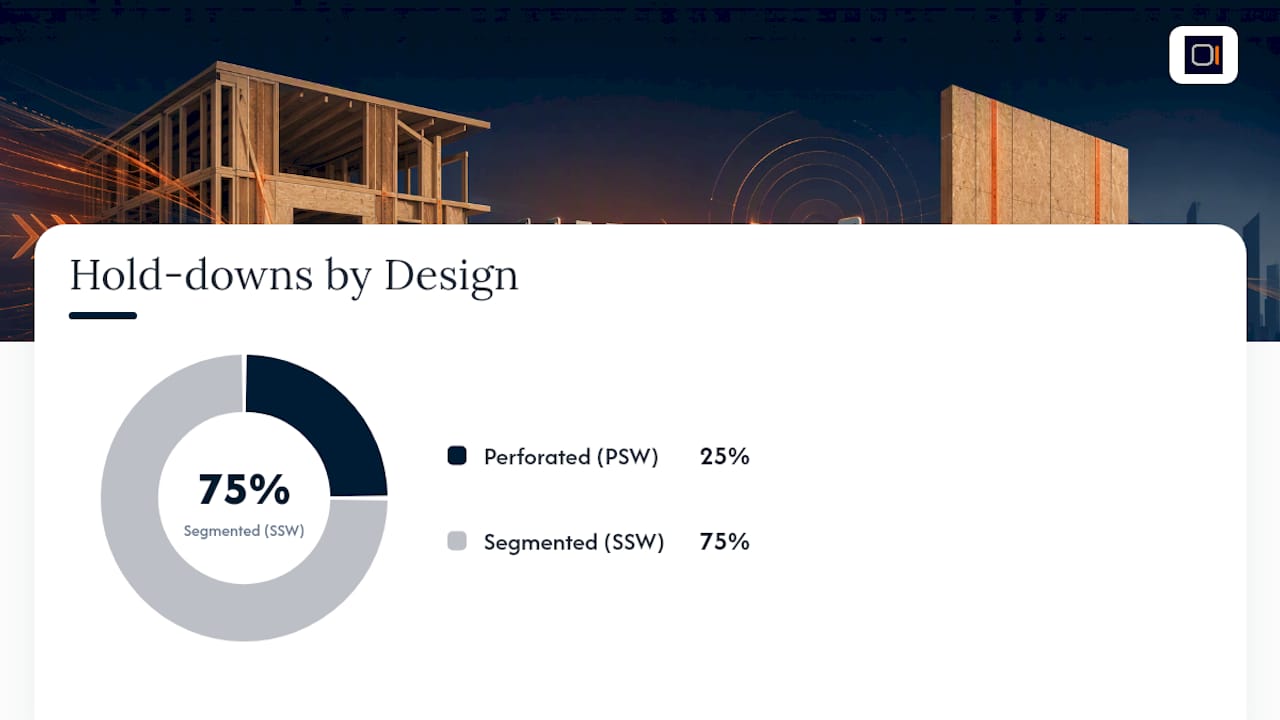
Consider a 24-foot exterior wall line on the first floor of a two-story wood-framed house, carrying a design story shear of 3,200 pounds at that level plus 1,800 pounds transferred down from the second story, for a total design shear of 5,000 pounds. The wall line includes two window openings, each 4 feet wide, positioned so that three full-height sheathed segments remain: an 8 foot segment, a 6 foot segment, and a 4 foot segment, for 18 feet of full-height sheathing out of the 24 foot total wall length. Plate height is 9 feet. Sheathing is 7/16 inch OSB nailed 4 inches on center at panel edges, giving a tabulated ν of 480 plf.
Perforated shear wall (PSW) calculation:
- Full-height sheathing ratio: 18 feet of full-height sheathing divided by 24 feet total wall length equals 0.75.
- Determine Co from the SDPWS table using that 0.75 ratio and the 9 foot maximum opening height relative to wall height. This yields a Co value in the range the SDPWS Chapter 4.3 table provides for that sheathing ratio, roughly 0.85 for this configuration.
- Calculate Vwall: ν (480 plf) × Co (0.85) × ΣLi (18 feet) = 7,344 pounds of capacity against the 5,000 pound demand, an ample margin that suggests the nailing schedule could be relaxed if hold-down count matters more than nailing labor.
- Determine vmax at the full-height segments to size uplift anchorage, then apply a uniform hold-down capacity along the sill plate rather than concentrated hardware at each segment.
- Hold-down count: Two, one at each end of the 24 foot wall line, sized for the summed two-story chord tension.
Segmented shear wall (SSW) calculation:
- Each of the three segments (8 feet, 6 feet, 4 feet) is checked independently against its share of the 5,000 pound demand, distributed by relative rigidity or tributary length.
- Each segment's aspect ratio is checked against the 3.5:1 limit. The 4 foot segment at 9 foot height comes in at 2.25:1, within limits, but a narrower segment elsewhere on the plan might not clear that bar.
- Vwall for each segment uses the same ν value (480 plf) with Co set to 1.0, since segmented design applies no adjustment factor.
- Hold-down count: Six, one at each end of all three qualifying segments, each sized to that segment's individual chord tension.
| Factor | Perforated (PSW) | Segmented (SSW) |
|---|---|---|
| Full-height sheathing required | 18 ft | 18 ft |
| Hold-downs required | 2 | 6 |
| Adjustment factor applied | Co ≈ 0.85 | None (Co = 1.0) |
| Anchorage approach | Uniform sill anchorage plus end hold-downs | Concentrated hold-down per segment |
| Calculation effort | Higher (requires Co lookup) | Lower (direct per-segment check) |
The comparison here matches what Structure Magazine's worked examples consistently show: PSW cuts hold-down count from six to two on this wall line, a real savings in hardware and field inspection points, at the cost of the extra Co calculation and the SDPWS table lookup it requires. On a project with many similar wall lines, that hardware reduction compounds fast. On a one-off wall with only a single opening, the segmented approach's simplicity may make it the faster path to a stamped set.
What Detailing Mistakes Cause the Most Field Problems?
The gap between a correct calculation and a correctly built wall shows up in a small, repeating set of field issues. Collector and diaphragm coordination errors top the list: a structural plan that assumes a continuous rim collector, while the architectural plan shows a stair opening interrupting that exact rim, leaves a load path with no way to close the gap without a change order.
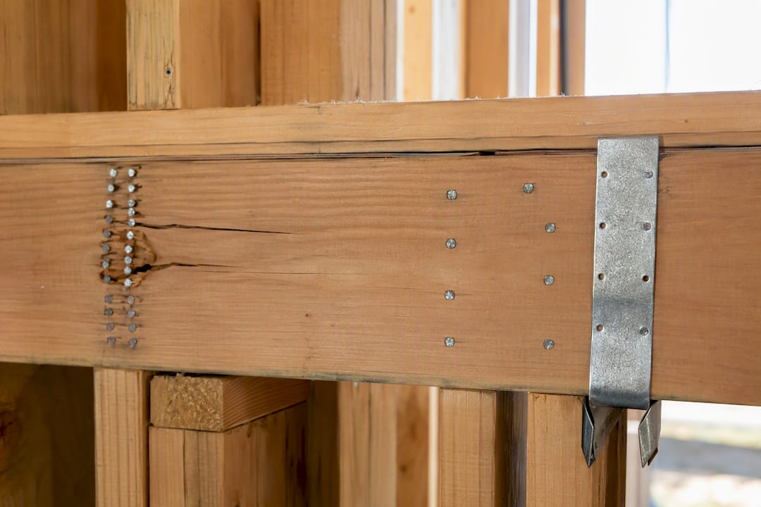
Rim joist splitting from over-dense nailing is a close second. Cramming a high nail count into a short rim segment to hit a tabulated shear value often splits the wood before it ever sees design load. Field-tested detailing guidance recommends staggering the nail rows or substituting a shear clip that transfers load into the top plate instead of concentrating every fastener in the rim itself.
Over-crediting gypsum is a subtler but equally common error. A designer includes gypsum's shear contribution in the Vwall calculation without confirming the interior fastening schedule actually matches the code table's assumed screw pattern. When the drywall crew uses standard screw spacing instead of the tighter pattern the credit requires, the wall's real capacity falls short of what the drawings claim, a gap that's invisible until someone checks the finished fastening against the design assumption, according to Penn State's comparison of shear wall design methods.
A few practices head off most of these problems before they reach the field:
- Cross-check the structural collector plan against the architectural floor plan for every stair, chase, or opening that could interrupt a rim.
- Specify staggered nailing or a shear clip alternative anywhere the calculated nail spacing falls under about 3 inches on center.
- Require gypsum fastening schedules on the drawings whenever gypsum shear credit is used, not just a general note referencing the code section.
- Request shop drawings for any FTAO connection or unusual strap configuration before framing begins, since these details are the hardest to correct after the fact.
How Does Seismic Design Change Wood Shear Wall Detailing?
Seismic demand changes wood shear wall design in ways wind loading doesn't, mainly because seismic forces are cyclic and reversing rather than pushing in a single direction. That reversal matters most at connections: a hold-down or strap sized only for one-way wind uplift may not perform the same way under repeated load reversal, which is why seismic detailing tends to favor ductile connections and more conservative nailing patterns near wall ends.
Higher seismic design categories also tighten the aspect ratio and sheathing continuity requirements beyond what a wind-only project would need, and they often push designers away from FTAO toward PSW or SSW, simply because the load path through straps and blocking is harder to verify for cyclic performance than continuous sheathing is.
Redundancy factors specific to seismic design can increase the required design force at a given wall line depending on how many shear wall lines resist load in that direction, a check that doesn't have a wind equivalent. That means a wall line that comfortably passes a wind check can still fail a seismic check purely because the building doesn't have enough redundant lateral lines in that direction, independent of the wall's own capacity.
Nail spacing near panel edges tends to run tighter under high seismic demand, which loops directly back to the rim-splitting issue covered above. On a high seismic design category project, staggered nailing or shear clips aren't just a nice-to-have detail; they're often what keeps a tight nail schedule from splitting the framing during construction, before the building ever sees an earthquake.
What Fire and Durability Factors Affect Wood Shear Walls?
Fire resistance for wood shear walls depends heavily on the assembly around the structural sheathing, not the sheathing itself. A single layer of 7/16 inch OSB has no inherent fire rating on its own, which is why fire-rated assemblies typically add a layer of Type X gypsum board on the interior face, an assembly that also happens to interact with the gypsum shear credit question covered earlier. Coordinating those two requirements, fire rating and shear credit, on the same wall matters because the fastening pattern that satisfies one doesn't automatically satisfy the other.
Party walls and walls near property lines usually carry the strictest fire-rating requirements, and those same walls frequently double as primary shear wall lines in attached housing and townhome projects. That overlap means the fire-rated assembly specification and the structural shear specification need to be reconciled on the same set of drawings rather than developed independently by different trades.
Durability concerns center on connector hardware more than the wood framing itself. Hold-downs, straps, and anchor bolts installed in exterior walls or near grade need corrosion-resistant coatings or stainless steel hardware, particularly in coastal environments or anywhere pressure-treated lumber contacts the connector, since the chemicals in some treated lumber accelerate corrosion in standard galvanized hardware. Specifying the correct hardware finish at the design stage avoids a hold-down that meets its rated capacity on paper but corrodes well before the building's service life is over.
How Does Moisture Affect Wood Shear Wall Performance?
Moisture is the quiet variable that undermines otherwise correctly calculated wood shear wall design. Wood structural panels lose stiffness and shear capacity when they absorb moisture, and repeated wetting and drying cycles can degrade the panel-to-framing connection well before any visible decay appears.
Bottom plate condition deserves particular attention since it sits closest to grade and carries both the hold-down anchorage and the sill nailing that ties sheathing into the foundation. A bottom plate that's absorbed moisture from a slab without a proper vapor barrier can lose fastener holding capacity at exactly the connection where hold-down tension needs to transfer reliably.
Sheathing installed wet, or exposed to weather for an extended period before the building is dried in, can develop swelling at panel edges that changes how the panel interacts with its nailing pattern. A swollen panel edge doesn't hold nails the same way the tabulated ν values assume, since those values are based on properly seasoned material installed to spec.
Pressure-treated bottom plates, required in most jurisdictions where wood contacts concrete, need fastener and hardware compatibility checks, since standard fasteners can corrode faster in contact with certain treatment chemicals. Specifying hot-dip galvanized or stainless connectors at the sill plate interface protects the exact connection where uplift and shear forces both concentrate.
How Do Engineers Verify Wood Shear Wall Designs?
Verification for wood shear wall design happens at two levels: the tabulated values themselves and the specific design's calculations. The tabulated unit shear values (ν) in SDPWS trace back to full-scale cyclic and monotonic testing performed under ASTM standards, which is why substituting an untested proprietary panel system for standard OSB or plywood requires either a code evaluation report or independent testing rather than assuming equivalent performance.
At the project level, verification means confirming that the calculated Vwall actually exceeds demand at every wall line, not just the governing one, since a wall line that looks conservative in one direction of loading can be marginal in the orthogonal direction. Structural analysis software can distribute story shear and check multiple wall lines simultaneously, but the underlying SDPWS equations and tabulated values still need to be applied correctly regardless of which tool performs the arithmetic, a distinction that becomes especially relevant when a design tool like ShearWise Pro's calculator or similar SDPWS and NDS-based platforms handles the computation.
Third-party plan review and peer review remain the most common verification step for wood shear wall design on permitted projects, particularly in higher seismic design categories where a reviewing engineer checks both the method selection and the specific Co, ν, and hold-down values against the governing code edition. Field verification through special inspection, confirming actual nailing schedules and hold-down installation match the approved drawings, closes the loop between the calculated design and the built structure.
Documenting Decisions So the Design Team Isn't Guessing Later
The gap between a correct wood shear wall design and a rework-plagued one usually isn't the calculation. It's what never made it onto the drawings. Every Co value, every tabulated ν, and every hold-down schedule assumption belongs on the plans in a form the framer and the inspector can actually check against, not buried in a calculation package that sits in a project file no one on site ever opens.
Early coordination on openings matters more than most engineers give it credit for. Penn State's research on shear wall methods points out that architectural constraints, not structural preference, usually drive method selection in residential work. An architect who moves a window 18 inches after the structural set is complete can turn a clean PSW wall line into one that no longer meets the full-height sheathing ratio Co assumed. Getting that layout locked before running final numbers saves more redesign hours than any calculation shortcut.
My own bias, for what it's worth: permit-level details should stay conservative. Optimize the nailing schedule and hold-down count during shop drawing review, once the framer's actual material and hardware availability are known, rather than chasing efficiency on the first submission when a small layout change can undo the whole calculation anyway.
— Evalin
Speed Up Wood Shear Wall Design With a Purpose-Built Calculator
Every calculation walked through above, story shear distribution, Co lookup, ΣLi, vmax, hold-down sizing, chord forces, gets faster and less error-prone with a tool built specifically for it. There are focused shear wall calculators and report platforms built around workflows covering 1 and 2-story wood-framed projects.

Some shear wall calculator platforms organize wall lines, openings, and full-height segments in one place, then compute hold-down forces, transfer strap requirements, and story drift checks from those inputs directly. Certain platforms handle both segmented and perforated method logic, allowing switching between these approaches on the same wall line without restarting the calculation from scratch. Some software exports clean PDF reports formatted for permit submission and reviewer coordination, which is useful on multi-story residential and light commercial wood projects where hold-down counts and collector details are often flagged by plan reviewers.
Engineers, architects, designers, drafters, and contractors working residential wood-framed jobs can try ShearWise Pro's shear wall calculator with three free watermarked reports before committing to a subscription. Walk through the tutorial library to see the perforated and segmented workflows in action, or head to ShearWise Pro to start a trial on your next wall line.
Sources
- Perforated shear wall design (AWC)
- Wood shear wall design examples for wind (Structure Magazine)
- Wood-frame shear wall and diaphragm design (WoodWorks presentation)
- Shear wall design in residential construction: a comparison of methods (Penn State)