

Transfer straps, formally called tension-resisting connectors, are steel plates or coil-cut strips that transfer localized tensile forces across discontinuities in wood-framed assemblies. In practice, your first move is to establish the design force at each strap location, select a strap family whose published allowable load meets or exceeds that demand, confirm the fastener schedule and development length into the adjacent pier, specify the corrosion finish, and cross-reference both SDPWS provisions and the manufacturer's current load tables before sealing the drawings.
Immediate design checklist:
- Select a strap family (straight precut, coil, diaphragm spline, or mass-timber washer type) based on the connection geometry and required capacity
- Confirm development length into the adjacent shear pier, not just the opening header or sill
- Specify fastener type, count, and spacing explicitly; published loads are void without the correct fastener pattern
- Note the corrosion protection class (G90 galvanized, ZMAX, stainless) required by the exposure condition
- Reference SDPWS and NDS in the design notes, and attach the manufacturer's engineering letter or load table to the submittal package
- Use a shear wall calculator to verify that downstream framing members, hold-downs, and the foundation can accept the forces the strap delivers
Key Takeaways
Effective transfer strap design in wood buildings requires selecting the right strap family, verifying both steel and fastener capacity, and documenting the full load path from the strap through blocking, sheathing, and into the foundation.
| Point | Details |
|---|---|
| Specify fasteners explicitly | Published strap loads are void without the correct fastener type, count, and spacing on the drawings. |
| Straps vs. collectors in FTAO | Straps develop locally into the adjacent pier; collectors (top/bottom plates) must run the full wall length per SDPWS. |
| Check both capacity sources | Confirm steel tensile capacity and fastener group capacity; the lower value controls the design. |
| Require a pre-sheathing hold point | Inspect fastener count, edge distance, and strap flatness before sheathing covers the connection. |
| ShearWise Pro for strap schedules | The platform automates force extraction, strap scheduling, and downstream member checks for 1- and 2-story wood buildings. |
Table of Contents
- What do transfer straps actually do in a wood building?
- How do you read strap spec sheets and identify the right strap type?
- Which codes and standards govern transfer strap design?
- How are strap allowable loads established and checked?
- How should you detail straps around openings for FTAO?
- What installation requirements and QA checks matter most?
- How do you use Simpson Strong-Tie load tables without misreading them?
- Worked example: sizing a strap for an FTAO corner force
- A practical perspective on what engineers most often miss
- ShearWise Pro organizes your strap schedules and downstream checks
- Sources
What do transfer straps actually do in a wood building?
Structural straps are tension-resisting connectors that tie floor, wall, and roof assemblies together so the building resists wind and seismic loads as a single unit rather than as a collection of independent panels. That single-unit behavior is the entire premise of a continuous load path, and straps are often the element that closes the gap where framing members are interrupted.
Common situations that require a strap:
- Force Transfer Around Openings (FTAO): Windows and doors interrupt the shear wall, concentrating corner forces at the top and bottom of the opening. Straps carry those forces horizontally into the adjacent full-height piers.
- Chord and plate splices: Where top or bottom plates are lapped or where diaphragm chord members are interrupted, a strap restores tension continuity across the joint.
- Diaphragm spline connections: In mass-timber and panelized floor systems, spline straps connect panel edges to transfer diaphragm shear between adjacent panels.
- Uplift ties: Straps anchor roof framing or wall top plates to resist wind uplift, particularly at gable ends and ridge connections.
The load path that straps serve runs from the roof or floor diaphragm, through collectors (typically continuous top or bottom plates), through the strap itself, and into the shear pier, then down to the foundation. Every link in that chain must be checked. A strap that delivers force to a stud that cannot accept it has not solved the problem; it has moved it. Understanding lateral load distribution across the full wall line is the context in which strap placement decisions make the most sense.
How do you read strap spec sheets and identify the right strap type?
Strap families differ in geometry, gauge, and the type of connection they are designed to make. Knowing which family fits your condition before opening the load table saves significant time.
Principal strap families:
- Straight precut strap ties (e.g., Simpson Strong-Tie ST series): Flat, punched steel plates in fixed lengths. Used for wood-to-wood uplift, plate splices, and light FTAO applications. Allowable loads are typically based on steel tension calculations plus fastener capacity checks, which is why straight straps can often be load-rated without full empirical testing.
- Medium strap ties (e.g., MSTA series): Heavier gauge, longer precut straps for higher-demand uplift and splice applications. The MSTA24Z, for example, is specified for wood-to-wood uplift with published gauge, finish, and required fastener counts.
- Coil straps: Supplied in rolls and cut to length in the field. Useful when the required strap length is non-standard. Pneumatic fastening is practical with coil straps, which speeds installation on large projects.
- Diaphragm spline straps (e.g., MDSS, LDSS48): Designed for panel-to-panel connections in mass-timber and panelized floor diaphragms. The LDSS48 evolved specifically to address mass-timber chord and diaphragm spline demands with WSV subfloor screws.
- Mass-timber washer and angled-screw assemblies (e.g., CMSTC16): High-capacity connectors for CLT and glulam chord splices where conventional nail patterns are not practical. These typically require manufacturer engineering letters for the specific substrate.
Spec-sheet checklist — fields to extract before sizing:
- Allowable tensile load (at the required fastener count)
- Required fastener type, diameter, and count per side
- Gauge and width of the strap steel
- Corrosion protection class and applicable exposure category
- Permitted substrate (solid-sawn lumber, LVL, CLT, or combination)
- Reduction factors for wet service, load duration, or temperature
- Whether the published value is calculation-based or test-backed
- Edge distance and end distance requirements for the fasteners
- Installation notes (overlapping straps to increase capacity, centering requirements)
The table below summarizes the key spec-sheet fields to extract for the most common strap families. Verify all values against the manufacturer's current catalog before issuing drawings.
Source: Simpson Strong-Tie ST2215 product data; verify current values with manufacturer catalog.
Which codes and standards govern transfer strap design?
Three primary references govern strap design in wood-framed buildings, and all three should appear in your design notes and on the contract drawings.
Primary standards:
- AWC SDPWS (Special Design Provisions for Wind and Seismic): The governing standard for shear wall methodologies, including FTAO provisions. SDPWS defines collector requirements and the conditions under which FTAO detailing is permitted. It also establishes that collectors must run the full length of the shear wall, while straps need only be long enough to develop the induced force into the adjacent pier.
- NDS (National Design Specification for Wood Construction): Governs wood material properties, connection design, fastener withdrawal and lateral capacity, and load duration factors. Fastener capacity checks for strap connections reference NDS tables directly.
- Manufacturer engineering letters and technical bulletins: For any strap product used beyond its standard tabulated conditions (different substrate, higher load, overlapping straps), the manufacturer's engineering letter is the controlling document. Simpson Strong-Tie, for example, publishes engineering letters for CMSTC16 and LDSS48 applications that are not fully covered by the standard catalog.
A critical distinction that SDPWS provisions clarify is the difference between collectors and straps in FTAO design. Collectors (top and bottom plates or other full-length boundary elements) must run the full wall length. Straps that dissipate corner forces into adjacent piers need only extend far enough to develop the induced load. Conflating the two leads to either over-specified straps or, more dangerously, under-specified collectors.
SDPWS design note: When detailing FTAO shear walls, confirm that the collector element (typically the continuous top plate) is explicitly called out on the drawings as a full-length member, separate from the strap that handles the localized corner force. Omitting this distinction is one of the most common plan-check comments on FTAO submittals.
What to include on contract drawings:
- Strap designation, length, and orientation
- Fastener type (nail diameter and length), count per side, and spacing
- Corrosion protection class
- Reference to the applicable SDPWS section and manufacturer load table
- Blocking location and size
- Any reduction factors assumed in the calculation
How are strap allowable loads established and checked?
Two capacity sources govern every strap connection: the steel tensile capacity of the strap itself, and the fastener capacity of the nails or screws that attach it to the framing. The lower of the two controls.
Calculation logic:
- Steel tension capacity: For straight straps, the allowable tensile load is typically derived from the net section area of the strap steel multiplied by the allowable tensile stress for the steel grade. Because straight straps load in pure tension without the eccentricity or prying that complicates other connectors, calculated values are often reliable without full-scale testing.
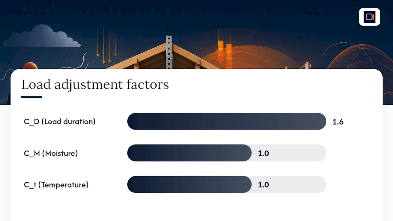
- Fastener capacity: Each nail or screw transfers a portion of the strap load into the framing. The total fastener capacity equals the number of fasteners per side multiplied by the allowable lateral load per fastener (from NDS tables), adjusted for load duration (C_D), wet service (C_M), and temperature (C_t) factors.
- Group action factor (C_g): When multiple fasteners act in a row along the strap length, NDS requires a group action reduction. For longer straps with many fasteners, C_g can reduce the effective fastener capacity meaningfully.
Symbolic design check:
T_required ≤ min(φ · F_t · A_net, n · Z' · C_g)
Where T_required is the strap tension demand from the shear wall analysis (including applicable load combinations and, for seismic, any overstrength factor Ω₀ required by the code), F_t is the allowable tensile stress for the strap steel, A_net is the net cross-sectional area at the critical hole pattern, n is the number of fasteners per side, and Z' is the adjusted allowable lateral load per fastener.
Statistic callout: For FTAO designs, Structure Magazine notes that stiffness verification is required alongside strength checks — a strap that is strong enough but too flexible can allow differential displacement that invalidates the FTAO assumption.
Full checklist of engineering checks:
- Strap tensile capacity (net section, steel grade)
- Fastener lateral capacity per NDS, with C_D, C_M, C_t adjustments
- Group action factor C_g for multi-fastener rows
- Edge distance and end distance for fasteners in the framing member
- Bearing capacity of the framing member at the strap termination
- Corrosion allowance: reduce net section for straps in wet or corrosive environments
- Downstream framing: confirm studs, blocking, and plates can accept the transferred force
- Foundation and hold-down: verify the load path continues below the strap termination
For connections outside standard tabulated conditions, use the manufacturer's engineering letter and document the assumed reduction factors explicitly in the calculation package.
How should you detail straps around openings for FTAO?
FTAO concentrates shear forces at the corners of openings. The corner force is not simply the wall shear divided by the pier length; it includes the accumulated diaphragm collector demand and the geometry-dependent amplification from the opening. Straps, blocking, and collectors share the transfer task, and each must be explicitly detailed.
How the corner force is distributed:
- The strap carries the horizontal tension component across the top or bottom of the opening
- Blocking transfers the force from the strap into the adjacent pier studs and sheathing
- The collector (continuous top or bottom plate) carries the accumulated shear along the full wall length
Strap length guidance:
Straps in FTAO do not need to span the full wall. They need to be long enough to develop the induced load into the adjacent pier, which means the strap must extend past the opening corner and into the pier by a distance sufficient to engage the required number of fasteners. The WoodWorks FTAO resource confirms this distinction: collectors run full length, straps develop locally. A strap that terminates at the rough opening edge without adequate embedment into the pier framing has zero capacity at that end.
Blocking and sheathing interaction:
Blocking at the top and bottom of the opening is not optional in FTAO. It provides the bearing surface that transfers the strap force into the pier sheathing and studs. Without solid blocking, the strap load has no path into the pier. Blocking panels in shear walls play a direct role in whether the FTAO detail functions as designed.
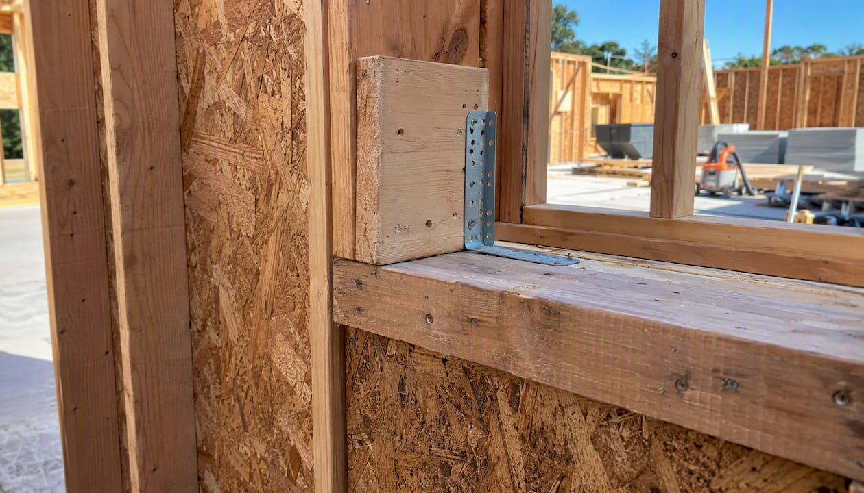
| FTAO detail element | Design requirement | Common error |
|---|---|---|
| Strap at opening top | Extend into pier; develop full fastener count | Strap terminates at rough opening edge |
| Strap at opening bottom | Same as top; confirm sill plate continuity | Missing sill strap or wrong nail count |
| Blocking at corners | Full-depth blocking between studs | Blocking omitted or undersized |
| Collector (top plate) | Continuous full wall length | Plate lapped without strap or scab |
| Sheathing fastening | Edge nailing into blocking and pier studs | Skipped nails at blocking edges |
Designer checklist for FTAO strap detailing:
- Calculate the corner force explicitly, not by inspection
- Select strap length to develop the required fastener count into the pier framing
- Specify blocking size, species, and connection to the strap and sheathing
- Call out the sheathing edge-nail schedule at the blocking and pier boundary
- Confirm the collector is continuous and explicitly noted on the drawings
- Verify the strap finish matches the exposure condition of the wall assembly
What installation requirements and QA checks matter most?
Field installation quality directly determines whether the strap achieves its designed capacity, and following guidance on how structural remodeling works for homeowners can help contractors communicate load-path changes effectively. A strap with two missing nails per side can lose a significant fraction of its allowable load, and a rippled strap introduces eccentricity that the design did not account for.
Step-by-step installer sequence:
- Confirm strap designation matches the drawing schedule before cutting or placing
- Position the strap centered on the framing member, not offset to one edge
- Begin fastening at the center of the strap and work outward toward each end; this keeps the strap flat and prevents the ripples that create eccentricity
- Drive fasteners to the specified diameter, length, and count per side; do not substitute a different nail diameter or length without engineering approval
- Verify edge distance from the fastener centerline to the framing edge meets the NDS minimum before driving
- Confirm full bearing behind the strap at both termination points; the framing must be solid, not a gap or notch
- For coil straps cut in the field, pneumatic fastening reduces labor and improves consistency, but the installer must still verify nail count per side against the schedule
QA inspection checklist:
- Fastener count per side matches the drawing schedule
- Fastener type (diameter and length) matches the specification
- Edge distances are within NDS limits
- Strap is flat with no visible waves or ripples
- Corrosion protection is intact; no bare steel exposed at cut ends of coil straps
- Strap termination lands on solid framing, not a gap
- Blocking is present and properly connected where required
- Any field changes are documented and submitted for engineering review before covering
Common field errors and corrections:
- Missing nails: Add the missing fasteners before sheathing covers the strap; do not accept a field note as a substitute
- Wrong nail type: Remove and replace; a 10d common nail and a 10d sinker are not interchangeable for published load values
- Short strap: If the strap does not develop the required fastener count into the pier, the connection is deficient; a longer strap or an overlapping second strap (per manufacturer guidance) is the correction
Pro Tip: Write a hold point into the inspection plan that requires the strap installation to be verified before sheathing is applied. Once the sheathing is on, confirming fastener count and edge distance is nearly impossible without destructive investigation.
How do you use Simpson Strong-Tie load tables without misreading them?
Simpson Strong-Tie publishes the most widely used strap product families in North American wood construction. Reading their tables correctly is a practical skill that prevents both under-design and unnecessary conservatism.
Key product families and their primary applications:
- ST series (e.g., ST2215): Light-gauge precut strap ties for wood-to-wood uplift and plate splices. The ST2215 is a 20-gauge, 1-5/16-inch-wide strap with G90 galvanized finish. Published loads require the correct fasteners installed in the specified hole positions.
- MSTA series (e.g., MSTA24Z): Medium strap ties at 16 gauge for higher uplift demands. The MSTA24Z carries a ZMAX finish for treated-lumber compatibility.
- MDSS / CMSTC16: Diaphragm spline and mass-timber chord splice straps. These products are test-backed and often require manufacturer engineering letters for specific CLT or glulam substrates.
- LDSS48: A lighter-gauge diaphragm spline strap developed specifically for mass-timber panel connections, tested with WSV subfloor screws. The LDSS48 evolution reflects the industry trend toward strap geometries that move higher diaphragm forces with fewer fasteners.
How to extract usable values from the load table:
- Read the allowable load column for the exact fastener count you can physically fit in the available framing length; do not interpolate between rows unless the table explicitly permits it
- Check the footnotes for load duration assumptions; most published values use C_D = 1.6 (wind/seismic) and must be reduced for other load combinations
- Confirm the substrate column matches your framing (solid-sawn vs. engineered lumber vs. CLT); allowable loads often differ by substrate
- Note whether overlapping two straps is permitted and what the combined capacity is; some families allow it, others do not
Quick-reference product selection checklist:
- Intended use: uplift, splice, FTAO corner, diaphragm spline, or mass-timber chord
- Published allowable load at the required fastener count
- Fastener type and count per side that achieves that load
- Finish class required by exposure condition
- Substrate compatibility confirmed
- Engineering letter required? Confirm availability before specifying
Always verify current manufacturer data before sealing. Product lines evolve, and a catalog from two years ago may not reflect current load values or fastener requirements.
Worked example: sizing a strap for an FTAO corner force
The following symbolic example walks through the sizing sequence for a strap at the top corner of a window opening in a wood-framed shear wall. No proprietary client data is used; all values are illustrative.
Step 1: Establish the design force
From the shear wall analysis, the corner force at the top of the opening is T_required = 2,400 lb (ASD, wind load combination, C_D = 1.6). This value comes from the FTAO calculation per SDPWS, accounting for the opening geometry and the accumulated collector demand.
Step 2: Select a candidate strap family
The connection is wood-to-wood at a double top plate, exposed to interior conditions. A medium precut strap tie (MSTA series) is a reasonable starting point. Pull the current Simpson Strong-Tie catalog and locate the MSTA row with an allowable load at or above 2,400 lb.
Step 3: Check steel tension capacity
Confirm the strap's net section capacity at the critical hole pattern exceeds T_required. For a 16-gauge strap, the net area after punched holes must be sufficient. If the catalog value already accounts for net section, confirm the footnote says so.
Step 4: Check fastener capacity
Assume the table requires 14 × 10d × 1-1/2 in. nails per side (7 each end) into Douglas Fir-Larch. Verify the adjusted lateral load per nail (Z') from NDS Table 11N, apply C_D = 1.6, C_M = 1.0 (dry service), C_t = 1.0, and calculate the group action factor C_g for 7 fasteners in a row. Confirm n × Z' × C_g ≥ 2,400 lb.
Step 5: Check edge distance and blocking
The strap terminates into the double top plate and must extend into the adjacent pier by enough length to engage all 7 fasteners per side. Confirm the pier width accommodates the fastener spacing and that full-depth blocking is present at the opening corner to transfer the strap force into the pier sheathing.
Step 6: Document assumptions
Record C_D, C_M, C_t, C_g, the net section area used, and the manufacturer table reference in the calculation package. Note the strap designation, length, and fastener schedule on the drawings.
Where a shear wall calculator fits:
- Automatically extracts the corner force from the wall line geometry and applied shear
- Consolidates strap designations into a schedule organized by wall line and opening
- Flags downstream member capacity issues (studs, plates, hold-downs) that the strap force creates
- Generates a PDF report with strap schedules and design notes formatted for permit submission
ShearWise Pro tutorials show how the platform organizes these checks so the engineer can focus on reviewing results rather than tracking force values across multiple spreadsheets. Always cross-reference the manufacturer's current engineering letter when the software output references a product outside standard tabulated conditions.
A practical perspective on what engineers most often miss
The specification omission that causes the most field problems is not a missing strap. It is a missing fastener schedule. Drawings that call out a strap designation but leave the fastener count to the installer's judgment are an invitation for under-nailed connections. Published loads are void without the correct fastener pattern, and that fact needs to be stated explicitly on the drawings, not buried in a general note.
Common trade-offs worth calling out in the spec:
- Precut vs. coil straps: Precut straps are faster to specify and easier to inspect, but coil straps give the installer flexibility when the required length is non-standard. Coil straps also allow pneumatic fastening, which improves consistency on high-volume framing crews.
- Overlapping straps vs. a thicker plate: Doubling a strap to increase capacity is permitted by some manufacturers and can be cost-effective, but it requires explicit engineering approval and a note on the drawings. A thicker plate connector may be cleaner to specify and inspect.
- Contractor labor vs. hardware cost: A higher-capacity precut strap with fewer fasteners often costs more in hardware but less in labor. On projects where framing labor rates are high, that trade-off favors the precut option.
Write inspection hold points into the contract documents that require strap installation to be verified before sheathing covers the connection. Acceptance criteria should state the strap designation, fastener type, minimum count per side, and confirmation that the strap is flat and fully bearing on solid framing. A note that says "install per manufacturer" is not an acceptance criterion; it is a delegation of the engineer's responsibility to the field.
The strap ties in shear design guide on the ShearWise Pro blog covers specification language in more detail, including example note formats that have held up through plan check.
ShearWise Pro organizes your strap schedules and downstream checks
Sizing a strap is one step. Tracking every strap across every wall line, opening, and story in a wood-framed building, and confirming that the downstream framing and foundation can accept each transferred force, is where projects lose time and introduce errors.

ShearWise Pro is built for exactly that workflow. The platform extracts strap forces directly from your shear wall calculations, generates a strap schedule organized by wall line and opening, and flags downstream member capacity issues before they reach the field. PDF reports include strap designations, fastener schedules, and design notes formatted for permit submission, so the engineer's calculation package and the contractor's field documents stay in sync.
The free trial gives you three watermarked reports, enough to run a complete wall line through the strap schedule and see how the output is organized. Sign up to try ShearWise Pro and generate a sample report for your next wood-framed project.
Sources
- Developing High-Capacity Tension Straps for Mass Timber Engineering (Simpson Strong‑Tie blog)
- Framing techniques: strap shear (AFT Construction blog)
- Structural framing straps you can install with a nail gun: tracing the load path (Pro Trade Craft)
- Simpson Strong‑Tie ST2215 strap tie product page (Fasteners Plus)
- Designing with force-transfer shear walls (Structure Magazine)