
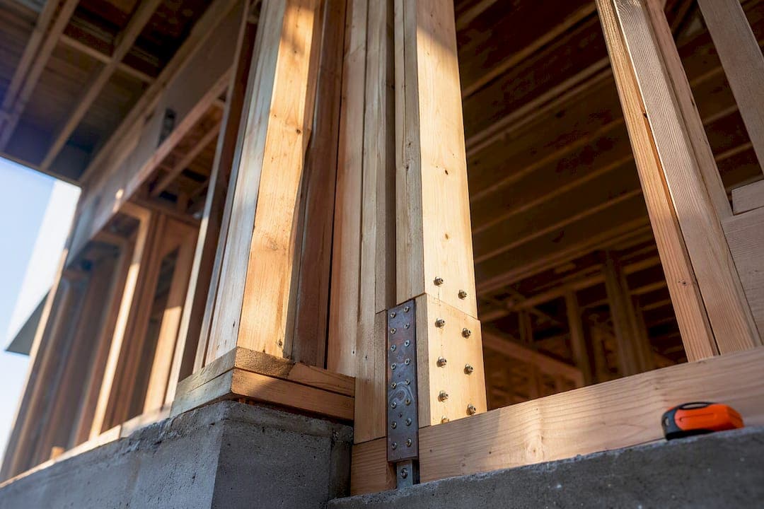
Wood shear wall chords are the vertical boundary members that resist the axial tension and compression forces created by overturning moment at each end of a shear wall segment. The tension chord resists uplift; the compression chord resists the downward axial reaction, and in perforated wall segments, SDPWS requires the compression chord force C to equal the tension chord force T. Three checks decide whether your chord design passes: the axial force calculation from overturning moment and story shear, the tension chord uplift and hold-down design, and the compression chord's axial stability and bearing capacity. The formula section and worked example below walk through all three.
TL;DR:
- Chord forces must be calculated for each wall segment, considering overturning moments and tributary dead loads, with special attention to multi-story accumulation.
- At perforated wall ends, the compression chord force must equal the tension chord uplift force, and proper load path continuity is essential.
- Hold-downs and anchor bolts require sizing for the calculated uplift force, with verification of foundation capacity, embedment, and bearing details to prevent failure.
- The compression chord's axial capacity and buckling stability depend on correct member sizing, bracing assumptions, and proper bearing area details.
- Using a consistent calculation workflow and specialized tools like ShearWise Pro helps prevent errors and ensures compliance with SDPWS and NDS requirements.
Table of Contents
- What Wood Shear Wall Chords Are Under SDPWS and NDS
- How to Calculate Chord Forces From Overturning Moment
- Tension Chord Design: Uplift, Net Section, and Hold-Downs
- Compression Chord Design: Axial Capacity and Buckling
- Segmented vs. Perforated Methods and What They Mean for Chords
- Worked Example: Chord Forces From Load to Final Check
- Detailing Notes: Splices, Straps, and Anchorage Layout
- Why a Repeatable Chord Calculation Workflow Matters
- Running These Calculations in ShearWise Pro
- Reference Reading for Chord and Hold-Down Design
- Sources
What Wood Shear Wall Chords Are Under SDPWS and NDS
A boundary chord is the vertical member at the edge of a shear wall segment that picks up the axial forces generated when lateral load tries to overturn the wall. In many single-story walls, the top and bottom plates plus the end studs act together as the chord. In taller walls or heavily loaded segments, engineers often specify a dedicated chord stud, built-up post, or engineered member sized specifically for the calculated tension and compression demand rather than relying on standard framing.
The Special Design Provisions for Wind and Seismic (SDPWS) published by the American Wood Council governs how you calculate and apportion these forces, and the NDS governs the member checks once you have them. SDPWS recognizes two design methods with different chord implications:
- Segmented method: Each full-height sheathed segment is designed independently, with its own chord forces computed from its own tributary shear and aspect ratio.
- Perforated method: The wall line is treated as one unit with openings, using a shear capacity adjustment factor, but each end of the perforated segment must still be designed for a compression chord force equal to the tension chord uplift force.
That equality, C = T at perforated segment ends, is one of the most frequently missed requirements in permit review. Engineers size the hold-down for uplift, then treat the compression side as an afterthought, when the code text on UpCodes is explicit that the compression chord needs the same design force and a continuous load path to the foundation.
Multi-story buildings raise the stakes further. Chord forces do not reset at each floor. The tension and compression demands from an upper-story wall segment accumulate into the chord below it, provided the segments align, which means your second-story chord calculation is not complete until you have checked whether it feeds forces into a first-story chord and, ultimately, the foundation. A continuous load path from roof to footing is not optional detailing polish. It is the mechanism that makes the whole overturning calculation valid in the first place.
How to Calculate Chord Forces From Overturning Moment
The core equation for wood structural chords is short enough to memorize, but the inputs are where most calculation errors hide:
T = M / e and C = M / e (with the C = T equality applying at perforated segment ends)
Where:
- T = tension (uplift) chord force
- C = compression chord force
- M = net overturning moment at the base of the wall segment
- e = the effective moment arm, typically the distance between the centroids of the tension and compression chords
The overturning moment itself comes from the story shear applied at each level times its height above the point you are checking, summed for every level that contributes load into that wall segment. Calcs follows the standard SDPWS convention: you take the overturning moment from lateral load, subtract a restoring moment from dead load acting on the tributary width of the segment, and the remainder is what the chord has to resist in tension.
M_net = (V × h) − (W_D × L / 2)
Where V is the story shear on the segment, h is the wall height, W_D is the dead load tributary to the segment width L. That restoring term is why identical wall segments on different levels of the same building can have wildly different hold-down requirements. A segment carrying more roof and floor dead load restores more of the overturning moment before the chord ever sees net tension.
Here is where practice diverges from theory in a way that catches less experienced reviewers off guard. On the tension side, engineers typically apply the full dead load tributary to the wall line as restoring moment. On the compression side, per the Enercalc Wood Shear Wall calculation module documentation, you use only the portion of dead load that is actually tributary to the compression chord stud, not the whole segment. Mixing those two conventions, using the full segment dead load on both sides, understates compression demand and overstates the restoring effect on tension. Both errors point the same direction: toward an unconservative chord.
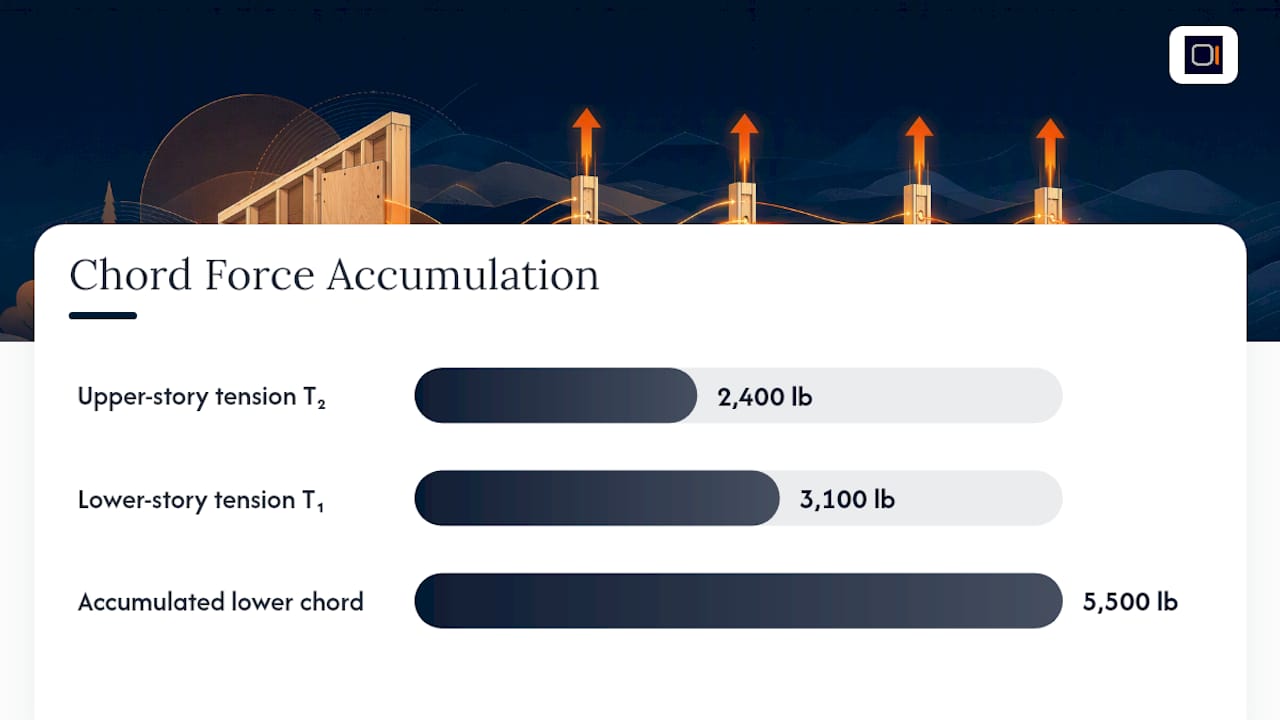
For multi-story accumulation, add the chord force computed at the story above directly into the chord force computed at the story below, assuming vertical alignment of the wall segments. A rough symbolic preview: if an upper-story segment generates T₂ = 2,400 lbs at its base, and the lower-story segment at the same location generates its own T₁ = 3,100 lbs from its own story shear and moment arm, the chord stud at the base of the lower story must be checked for T₁ + T₂ = 5,500 lbs, not 3,100 lbs alone. That accumulation is exactly the kind of value that review comments flag when it goes missing, and it is exactly what the full numeric example later in this article works through line by line.
Tension Chord Design: Uplift, Net Section, and Hold-Downs
Once you have the tension chord force T, the check itself is a straightforward NDS tension member calculation, but the setup matters more than the arithmetic. You compare the applied tension force to the member's adjusted allowable tension capacity, which starts from the reference design value F_t and applies the NDS adjustment factors relevant to your project: load duration factor (C_D), wet-service factor (C_M) if the framing is exposed to moisture, temperature factor (C_t), and the net-section area adjustment if the chord stud has bolt holes or notches reducing its cross-section.
Sizing and specifying the hold-down itself follows a repeatable sequence:
- Compute the required uplift capacity from the tension chord force, including any load combination factors your jurisdiction requires.
- Select a hold-down device rated at or above that uplift demand at the allowable stress level, not the ultimate capacity the manufacturer publishes elsewhere in its literature.
- Check anchor bolt embedment depth, edge distance, and spacing against the concrete or foundation capacity, since the hold-down is only as strong as what it is bolted into.
- Verify the connected wood member for local crushing at the hold-down bearing plate, particularly on narrower chord studs.
- Confirm the anchor-to-foundation load path continues downward without a gap, which matters most at podium slabs, cripple walls, and stepped foundations.
Pro Tip: Manufacturers publish both allowable and ultimate capacities for hold-down hardware, and it is easy to grab the wrong column under deadline pressure. Confirm you are comparing your ASD-level demand against the allowable capacity, not the higher ultimate number, before you finalize a hold-down selection.
The most common review-stopping mistakes are unglamorous but persistent: forgetting to reduce net section for bolt holes in the chord stud, double-counting dead load restoring moment by applying it at both the wall and the foundation check, and citing a hold-down's ultimate capacity as though it were the allowable value. Any one of these can flip a calculation from passing to failing once caught.
Compression Chord Design: Axial Capacity and Buckling
The compression chord check has three layers, and each one can independently fail even when the others pass. First, compare the computed compression force C against the member's allowable axial compression capacity from NDS, which starts with the reference compression value F_c and gross cross-sectional area before adjustment factors are applied.
Second, run the slenderness check. Compute the effective length-to-least-dimension ratio, apply the column stability factor C_P, and confirm the bracing assumptions you used, sheathing on one or both faces, blocking, or intermediate bridging, match what is actually shown on the framing drawings. A chord stud assumed continuously braced by sheathing that gets omitted from the final framing plan is a buckling failure waiting to be found in the field.
- Verify gross-section axial capacity (F_c × A × applicable adjustment factors) meets or exceeds computed C.
- Check kL/r slenderness ratio and apply the NDS column stability factor C_P.
- Confirm bearing perpendicular to grain at plates, sills, and hardware connection points, adding a steel bearing plate where the calculated bearing stress exceeds F_c⊥.
- Verify bracing assumptions used in the slenderness calculation match the actual sheathing and blocking shown on drawings.
Third, check bearing perpendicular to grain wherever the chord force transfers through a plate, sill, or hardware bracket. Undersized bearing area at these transitions causes crushing long before the member itself would fail in pure axial compression, and it is a detail that rarely gets its own line item on a calculation sheet.
When C equals T at a perforated segment end, that compression demand is often larger than what a segmented-method calculation would have produced for the same wall, since perforated design apportions less capacity per foot of sheathing. Detailing needs to reflect that: a chord sized adequately for tension and hold-down hardware but undersized for the matching compression force is a common gap between the calculation and the framing plan.
Segmented vs. Perforated Methods and What They Mean for Chords
Choosing between SDPWS's two design paths changes how chord forces get apportioned across a wall line, and it is worth deciding early rather than midway through a calculation set.
- Segmented method treats each full-height sheathed panel as its own isolated shear wall, computing chord tension and compression independently for each segment based on its own aspect ratio and tributary shear. It is straightforward to document but can produce larger required hold-downs per segment, since each one carries its full share of overturning without any credit for the wall line acting as a composite unit.
- Perforated method treats the entire wall line, openings included, as one unit and applies a shear capacity adjustment factor, often called C_o, that accounts for the reduction in effective capacity caused by door and window openings. This factor makes use of more of the sheathed wall area, but it comes with a firm consequence: the code requires the compression chord force to equal the tension chord force at each segment end, which typically drives up anchorage and load-path requirements compared to what a naive reading of the segmented approach would suggest.
The practical decision usually comes down to opening layout and available wall length. Walls with generous solid segments and few interruptions favor the segmented method for its simplicity. Walls with frequent openings and limited full-height sheathing often need the perforated method's capacity credit just to pass, accepting the added anchorage and force-transfer calculation that comes with it.
Worked Example: Chord Forces From Load to Final Check
Consider a first-story shear wall segment, 8 feet long and 9 feet tall, resisting a story shear from wind loading. The segment carries a dead load along its tributary width, and the chord centroids are spaced apart by a typical distance, roughly the segment length minus half the chord stud widths on each end.
- Compute overturning moment. M_OT = V × h = story shear times wall height.
- Compute restoring moment from dead load. W_D = dead load along tributary width, acting at the segment's midpoint.
- Compute net overturning moment. M_net = overturning moment minus restoring moment.
- Compute tension chord force. T = M_net divided by effective moment arm.
- Set compression chord force. For this perforated wall line, C = T per the code requirement noted earlier.
The tension check confirms the chord stud's net section, after any bolt hole reduction for the hold-down bolts, carries 1,653 lbs comfortably under its adjusted allowable tension value. The hold-down selection then needs an anchor bolt rated at or above that 1,653 lb allowable uplift, with embedment and edge distance verified against the foundation detail. The compression check runs the same 1,653 lbs against the stud's allowable axial capacity after applying the column stability factor for its unbraced length, and the bearing check confirms the hold-down plate transfers that force into the sill without exceeding perpendicular-to-grain bearing stress.
If any single check fails, the fix is usually one of three moves: upsize the chord member, select a larger hold-down and matching anchor, or add a bearing plate at the connection. Each of those changes maps directly back to the SDPWS and NDS clauses cited earlier in this guide, which is exactly the traceability a plan reviewer is looking for.
Detailing Notes: Splices, Straps, and Anchorage Layout
Calculation values only matter if the framing plan carries them through. Top plate splices at wall discontinuities need to transfer the full chord force across the joint when the plate itself is acting as part of the chord or as a collector; WoodWorks publishes specific splice detailing guidance for exactly this condition.
- Show top plate splice lengths and fastener schedules wherever a chord or collector plate is interrupted by a wall break or corner.
- Place transfer straps to route chord force around openings, offsets, or discontinuous framing, and list the strap model and fastener count on the plan, not just a generic callout.
- Keep hold-down anchorage clear of plumbing, electrical, and HVAC penetrations so the load path does not compete with trade routing during framing.
- Note on the calculation sheet exactly which SDPWS and NDS clauses back each chord and hold-down value, since that traceability is what plan reviewers ask for first.
Why a Repeatable Chord Calculation Workflow Matters
Manual chord calculations fail in predictable ways: a restoring moment applied twice, a hole reduction skipped on a net-section check, a multi-story accumulation that stops one level too early. None of those are conceptual errors. They are workflow errors, and they show up more often under deadline pressure than in a calm first pass.
A consistent calculation structure, the same sequence of overturning moment, chord force, tension check, compression check, every time, gives reviewers a predictable document to check against and gives field teams a hold-down schedule they can trust without re-deriving it. Judgment still matters most where SDPWS's standard assumptions break down: irregular diaphragms, unusual coupling between wall lines, or force-transfer paths that do not follow a simple perforated or segmented pattern. No workflow replaces that judgment. It just clears the routine errors out of the way so judgment gets applied where it is actually needed.
— Evalin
Running These Calculations in ShearWise Pro
Redoing the overturning moment, chord force, hold-down, and bearing checks by hand on every wall line is where most calculation sets lose hours, and where copy-paste errors from one segment to the next tend to creep in. ShearWise Pro is built specifically for 1-story and 2-story wood-framed projects, organizing wall lines, openings, full-height segments, hold-down forces, transfer straps, roof information, and story drift checks into one calculation set instead of a dozen scattered spreadsheets.

The platform exports clean PDF reports formatted for permit and review coordination, so the chord and hold-down values carry straight through to the document a plan checker actually reads. Tutorials walk through the wall line setup shown in this guide, and the free trial includes three watermarked reports so you can run your own project through it before committing to a subscription. Sign up to try ShearWise Pro on your next 1-story or 2-story wall line and see how the numbers line up.
Reference Reading for Chord and Hold-Down Design
- Design of Wood Shear Walls (SDPWS excerpt) | UpCodes
- Compression Chords Clause | UpCodes
- Calcs
- Splicing Shear Wall Top Plates | WoodWorks
- Common Shear Wall Design Mistakes to Avoid in 2026