

Yes, shear walls can include openings, but any opening that materially reduces panel shear capacity must be detailed on the plans and its edges reinforced to transfer shear stresses. Beyond that threshold, you pick a design path: segmented, perforated shear wall (PSW), or force transfer around openings (FTAO), depending on geometry and load path.
TL;DR:
- Formal analysis of openings in shear walls is required when they eliminate full-height segments, reduce pier aspect ratios below limits, or cut into existing walls after construction.
- The three accepted design methods are segmented, perforated shear wall, and force transfer around openings, with each suited to different geometries and load conditions.
- Accurate fastening details, such as minimum nail edge distances and proper blocking, are essential to ensure open-insertion shear wall designs meet code demands.
- Near-wall corners or end zones, openings can compromise load transfer and require maintaining a minimum sheathed width or using FTAO methods for better load sharing.
- Using dedicated software like ShearWise Pro simplifies compliance checks, allows quick modeling of complex openings, and produces permit-ready documentation.
Table of Contents
- When Does a Shear Wall With Openings Require Formal Analysis?
- Segmented, PSW, or FTAO: Which Method Fits Your Wall?
- Design Limits Every Engineer Needs to Check on Walls With Openings
- Field Detailing That Makes an Openings Design Actually Work
- A Worked Example: Applying FTAO to a Wall With Two Openings
- Software Outputs That Speed Openings Design and Review
- Seismic Loads vs. Wind Loads: Why Openings Behave Differently
- How Wall Material Changes Openings Design: Wood, Concrete, and Masonry
- Retrofitting an Existing Shear Wall to Add or Modify Openings
- Openings Near Corners and Wall Edges: Where Standard Methods Break Down
- Try ShearWise Pro for Your Next Openings Design
- What I'd Tell Any Engineer Sizing Up an Opening
- Sources
When Does a Shear Wall With Openings Require Formal Analysis?
Code language is blunt on this point. Per IBC guidance summarized by WoodWorks, any opening in a shear panel that materially affects its strength has to be detailed on the plans, with edges reinforced to carry shear stress across the gap. That single sentence covers most of what plan reviewers check first.
The AWC's Special Design Provisions for Wind and Seismic (SDPWS) governs the actual design math, laying out three accepted methods and the aspect-ratio tables each one uses. Most lab data behind those tables traces back to ASTM E2126 cyclic testing, the CUREE protocol that has become the standard way to rack a wall in a lab and record how it fails.
In practice, you need formal opening analysis when any of these apply:
- An opening narrows a full-height segment or eliminates one entirely.
- Remaining piers fall below the aspect-ratio limits for your chosen method.
- Cumulative opening area near a diaphragm boundary starts eating into the shear line's total capacity.
- An opening gets cut into an existing, already-calculated wall after construction, whether for a new window or a mechanical chase.
Small, isolated MEP penetrations (a single plumbing vent, a low-voltage bore) typically fall under de minimis provisions and don't trigger full reanalysis. A rough opening for a door or window almost always does.
Segmented, PSW, or FTAO: Which Method Fits Your Wall?
SDPWS recognizes three ways to design a wood-frame shear wall around openings, and each one trades simplicity for flexibility in a different place. Picking wrong doesn't just cost you time. It can force a wall redesign after framing is already up.
- Segmented method. You treat each full-height sheathed segment between openings as its own independent shear wall, sum their capacities, and hold down each one individually. It's the most conservative approach and the easiest to explain to a reviewer, but on a wall with several openings you can end up with a hold-down at nearly every segment end. The AWC's own comparison notes a segmented wall might need eight hold-downs where a perforated design needs two.
- Perforated shear wall (PSW). PSW treats the whole wall line as one system, applying a capacity reduction factor based on total opening area, and only requires hold-downs at the wall ends. That cuts hardware and installation labor significantly, but it only works within specific pier aspect-ratio limits, and SIP-specific testing found PSW predictions run conservative for several structural insulated panel configurations, meaning actual capacity often exceeds the calculated value.
- Force transfer around openings (FTAO). FTAO keeps the sheathing continuous across the opening and uses straps and blocking to route forces around it, following APA's technical guidance. This is your go-to when piers are narrow, openings sit asymmetrically, or you've got multiple openings stacked in one wall line. APA's FTAO calculator handles the strap-force math so you're not deriving it by hand every time.
Pro Tip: If a segmented or PSW design fails aspect-ratio checks on a narrow pier, don't assume the wall is dead. FTAO defines pier height (h) as the opening height adjacent to that pier rather than full wall height, which frequently lets a design pass that would otherwise fail.
Design Limits Every Engineer Needs to Check on Walls With Openings
Numeric limits are where designs actually get rejected in plan review, not conceptual method selection. Aspect ratio (height to width) governs every method, but the definition of "height" shifts between approaches. Segmented and PSW measure full wall height for each pier. FTAO measures the adjacent opening height instead, a distinction from APA's testing program that often makes FTAO the only viable path on tight piers.
Fastener detailing matters just as much as geometry. Minimum nail edge distance into sheathing is 3/8 inch, with 1/2 inch recommended for high-load applications, and panels should be installed with a 1/8 inch gap at joints to allow for expansion without crushing edges.
| Design factor | Typical requirement | Notes |
|---|---|---|
| Minimum nail edge distance | 3/8 inch (1/2 inch for high-load) | Per JLC field guidance |
| Panel joint gap | 1/8 inch | Prevents buckling from moisture swell |
| Blocked vs. unblocked panels | Blocked required for higher capacities | Unblocked walls carry reduced tabulated values |
| High aspect-ratio piers | Reduction factor applied per SDPWS | Method-specific tables govern |
Post-construction openings need special handling. Cutting a new window into an existing wall almost always requires added blocking, new edge nailing along the cut, and a reinforcement strap sized to replace the lost sheathing continuity.
Field Detailing That Makes an Openings Design Actually Work
A calculation is only as good as its execution on-site. FTAO walls depend on continuous sheathing across the opening head and sill, with straps carrying tension forces around the corners and blocking transferring load between framing members. The strap layout has to align with the calculated force path, not just look reasonable to the framer.
Hold-down hardware choice matters beyond just capacity rating. Rod-type hold-downs need accessible anchor nuts for torque verification; bracket-style hold-downs need full nail-hole fill to develop their rated capacity. Check both during framing, not after drywall goes up.
A few detailing habits separate clean inspections from repeated callbacks:
- Stitch-nail double-stud seams at the same spacing as panel edge nailing, since skipping this creates a weaker built-up member instead of one solid post.
- Avoid shiners (nails that miss framing and clinch on the back side) at every panel edge, especially near hold-down posts.
- Confirm nail penetration depth meets the minimum for the specified fastener, not just placement.
- Verify blocking is continuous behind every horizontal panel joint, not just at the top and bottom plates.
Pro Tip: Ask your framing crew to leave hold-down anchor nuts exposed and untaped until the inspector signs off. Covering them early is one of the most common causes of a failed framing inspection.
A Worked Example: Applying FTAO to a Wall With Two Openings
Here's how a typical FTAO design moves from geometry to permit-ready output on a common residential wall line.
- Define the wall and loads. Say you have a 24-foot wall line, 9 feet tall, carrying a seismic shear demand of 1,800 pounds per linear foot at the base, with a door opening and a window opening breaking up the sheathing.
- Identify segments and openings. Map the full-height sheathed segments, then note each opening's width and height. Calculate the height of the pier adjacent to each opening, since that's the FTAO aspect-ratio input rather than the full 9-foot wall height.
- Select the method. With a narrow pier next to the window failing segmented aspect-ratio limits, FTAO is the practical choice here, keeping the wall sheathed continuously rather than treating each segment as isolated.
- Compute strap forces. Using the opening geometry and unit shear, calculate the tension force each strap must resist at the opening corners, then size straps and their nailing pattern accordingly.
- Determine hold-down forces. Calculate overturning forces at the wall ends based on the full wall height and applied shear, then select hold-down hardware rated for that demand.
- Document for permit. Your plan set should show hold-down forces and locations, strap sizes and placement, blocking layout, the nailing schedule, and a reference note to the design method and testing standard used.
Software Outputs That Speed Openings Design and Review
Running segmented, PSW, and FTAO checks by hand for the same wall, just to see which one clears aspect-ratio limits, eats a surprising amount of billable time. A purpose-built tool cuts that iteration down to minutes instead of a redrawn spreadsheet each time.
A focused shear wall program should generate:
- A wall-line layout showing every opening and full-height segment.
- Segment identification with calculated aspect ratios flagged automatically.
- A hold-down force table tied to each wall end or pier.
- A strap schedule sized to FTAO force-transfer calculations.
- Story drift checks for two-story wood-framed buildings.
- A clean PDF report formatted for permit submission and reviewer coordination.
ShearWise Pro's tutorials walk through modeling a wall with mixed openings end to end, which is a faster way to confirm your method choice than reworking the math three separate times by hand.
Seismic Loads vs. Wind Loads: Why Openings Behave Differently
Seismic and wind demands don't stress an opening the same way, and treating them interchangeably is a common design error. Seismic loading is cyclic and reversing, meaning a pier next to an opening gets racked back and forth repeatedly rather than pushed in one direction. That reversing behavior is exactly what ASTM E2126 cyclic testing is built to replicate, and it's why lab-derived reduction factors for openings tend to be seismic-governed in high-hazard regions.
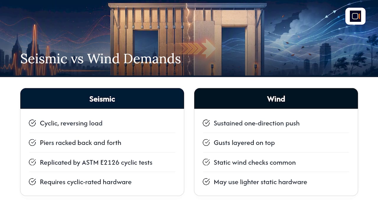
Wind loading is typically closer to a sustained, one-direction push, with gust effects layered on top. A wall that performs fine under a static wind check can still under-perform in a seismic cyclic test if the opening detailing (strap connections, nailing at reversing load points) wasn't designed for repeated load reversal.
The practical difference shows up in strap and hold-down selection. In high-seismic zones, connections around openings often need hardware rated for cyclic performance, not just a static capacity number. In wind-governed regions, the same wall might pass with lighter connection hardware because the load path never reverses direction the way it does during an earthquake.
Aspect-ratio limits themselves don't change between seismic and wind design, since SDPWS applies the same geometric tables regardless of load type. What changes is the unit shear demand feeding into those tables, and how conservatively you should treat any opening that concentrates stress at a corner or narrow pier. A wall in a coastal wind zone and a wall in a seismic zone can use identical FTAO detailing, but the strap force calculation behind each one comes from a very different demand side.
How Wall Material Changes Openings Design: Wood, Concrete, and Masonry
Wood-frame shear walls dominate residential construction, and everything covered so far, segmented, PSW, FTAO, applies specifically to wood-frame assemblies under SDPWS. Structural insulated panels (SIPs) fall into a related but distinct category. SIPA's technical bulletin found PSW methods produce conservative results for tested SIP wall configurations with openings, but SIP panel connections and foam-core behavior mean you can't just port wood-frame nailing schedules over directly. If your project mixes SIP walls with conventional framing, review SIP panel installation and connection detailing separately rather than assuming wood-frame FTAO details transfer as-is.
Concrete and masonry shear walls handle openings through an entirely different mechanism. Instead of sheathing, straps, and nailing, reinforced concrete and masonry walls rely on continuous reinforcing steel around the opening perimeter, typically doubled bars at the jambs, head, and sill, sized to replace the tension and shear capacity lost to the void. There's no equivalent to a PSW capacity-reduction factor here. Every opening in a concrete or masonry shear wall gets an explicit reinforcement design at its edges, governed by ACI 318 or the applicable masonry code rather than SDPWS.
The practical takeaway for mixed-material projects: never assume an opening detail that works in one material transfers to another. A wood-frame FTAO strap and a concrete jamb reinforcement bar are solving the same structural problem with completely different mechanics, and code compliance for each lives in a separate document.
Retrofitting an Existing Shear Wall to Add or Modify Openings
Cutting a new opening into an existing shear wall, or enlarging one for a renovation, is one of the more common calls structural engineers get on remodel projects. The wall was designed and built as a continuous or segmented shear-resisting element, and now someone wants a bigger window or a new door where sheathing used to carry load.
Start by identifying what method the original wall was likely designed under. Older wood-frame construction often predates PSW or FTAO provisions entirely and may have been designed as simple segmented full-height panels, which actually simplifies your retrofit path since you're just removing capacity from an identifiable segment rather than untangling a perforated wall's distributed capacity assumptions.
Once the opening is cut, the retrofit generally needs new blocking around the rough opening, added edge nailing along the cut sheathing lines, and a strap or reinforced header connection that restores the load path the original sheathing provided. In many cases, retrofitting with an FTAO-style detail, continuous new sheathing patched around the opening with straps at the corners, is more practical than trying to force the altered wall back into a segmented capacity calculation.
Where the original wall capacity was already tight, a retrofit opening may require adding capacity elsewhere on the same wall line: a new full-height segment nearby, an upgraded hold-down at the wall end, or in some cases a supplemental shear wall on an adjacent line to make up the difference. Always verify the retrofit against current code even if the original wall predates it. Plan reviewers evaluate retrofit work under today's provisions, not the code in effect when the house was built.
Openings Near Corners and Wall Edges: Where Standard Methods Break Down
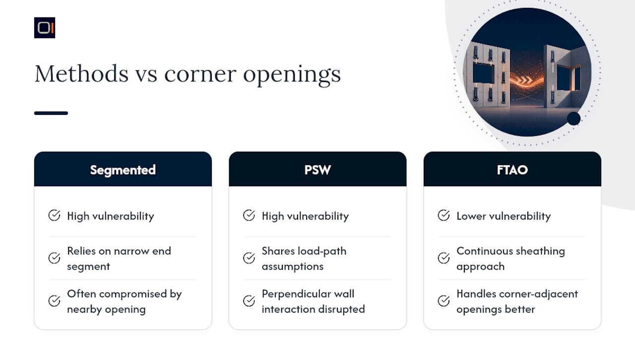
Openings placed near a wall corner or at the very end of a shear wall line create problems that standard segmented, PSW, and FTAO tables don't always address cleanly. The end zones of a shear wall carry the highest overturning forces, since that's where hold-downs anchor the entire wall's rotational tendency. An opening that crowds that end zone leaves less sheathing width to develop the hold-down force, which can govern the design even when the wall's overall shear capacity looks adequate on paper.
Corner conditions add a second complication: perpendicular walls meeting at a building corner often share load path assumptions that a nearby opening can disrupt, particularly when both walls are shear-resisting lines. An opening close enough to a corner can reduce the effective width available for corner framing, hold-down blocking, and the perpendicular wall's own end post.
The practical fix in most cases is maintaining a minimum solid sheathed width between an opening and the nearest wall end or corner, sized to accommodate the hold-down hardware and its required edge nailing, not just the bare code minimum. When geometry doesn't allow that buffer, FTAO's continuous-sheathing approach usually handles a corner-adjacent opening better than segmented or PSW, since it doesn't rely on isolating a narrow end segment that the opening has already compromised.
Engineers should treat any opening within roughly one wall height of a corner as a flag for closer review, even if standard aspect-ratio checks pass. The insight worth carrying into every review: an opening near a corner isn't just a local sheathing loss, it's a change to how the whole wall line shares load with its perpendicular neighbor, and treating it as an isolated panel problem misses that interaction.
Try ShearWise Pro for Your Next Openings Design
ShearWise Pro is the direct alternative to reworking segmented, PSW, and FTAO checks by hand every time an opening shifts on a revised floor plan. Instead of rebuilding a spreadsheet for each method, you lay out wall lines, mark openings and full-height segments, and let the platform calculate hold-down forces and strap schedules across both stories at once.

The output is a clean PDF report built for permit submission and reviewer coordination, covering hold-down tables, strap schedules, blocking notes, and story drift checks in one document instead of scattered hand calculations. For anyone still deciding between methods on a tight pier or an asymmetric opening layout, that speed matters as much as the accuracy.
If you want to see how a wall with mixed openings gets modeled from start to finish, the ShearWise Pro tutorials walk through the workflow end to end. Otherwise, head to the shear wall calculator program and start a free trial. Three watermarked reports let you test the full workflow on a real project before committing to a subscription.
What I'd Tell Any Engineer Sizing Up an Opening
My decision rule is simple: default to segmented when a wall has one clean opening and room to spare, reach for PSW when you want fewer hold-downs and the geometry fits its aspect-ratio limits, and go FTAO the moment a pier is narrow, an opening sits off-center, or you've got more than one opening competing for the same wall line.
Before framing starts, I want a plan set showing hold-down locations, strap sizes, blocking layout, and a note on which method and test standard governed the design. Skipping that documentation is what causes rework at inspection, not bad math.
Lab-backed methods exist because hand-waving an opening's effect on capacity is how walls fail. Use a calculator or dedicated software to check your assumptions twice; a five-minute rerun beats a redesign after framing.
— Evalin
Sources
- APA — Force transfer around openings (FTAO)
- JLC — Sheathing and shear panel field guide
- SIPA Technical Bulletin No.12 — Design of SIP shear walls with openings