
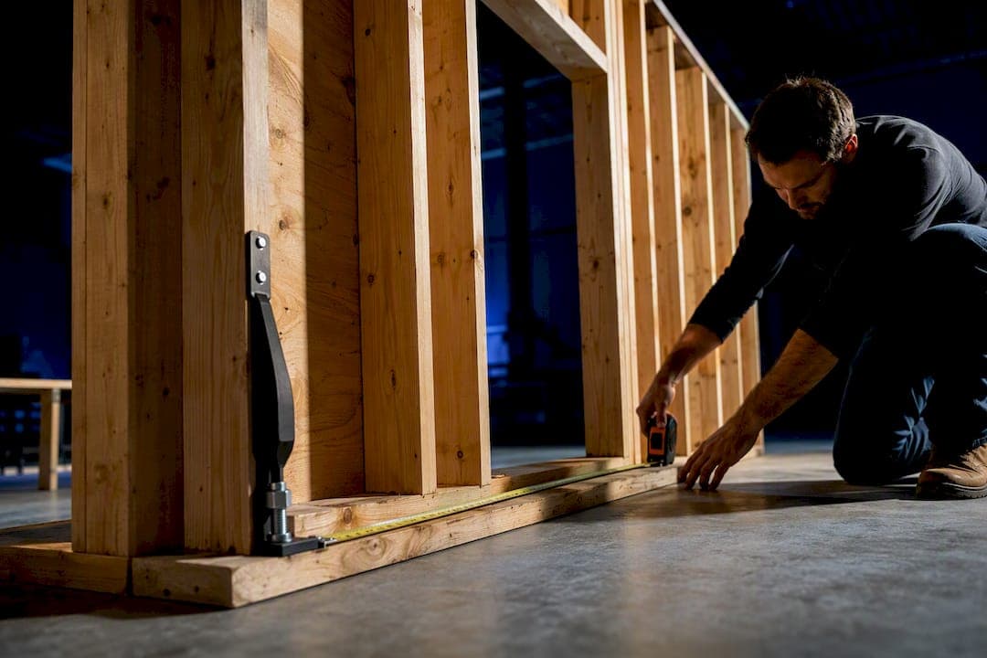
This article gives you two reproducible, code-referenced worked examples: a wood shear wall solved by both the segmented and perforated methods, and a reinforced concrete shear wall checked by hand against ACI 318. Every step cites SDPWS/WFCM, ASCE 7, or ACI 318, so you can trace each number back to its clause. Follow the calculations in order and you will end up with the same intermediate values a plan reviewer expects to see, plus a checklist for turning them into a permit-ready report. Software tools can automate this same sequence for wood buildings if you'd rather skip the spreadsheet.
TL;DR:
- The example shows that for a 32-foot-wide wood shear wall, a unit shear of 75 psf is typical and serves as the basis for both segmented and perforated methods.
- The segmented method ignores openings and requires at least 9.2 feet of full-height sheathing along the wall line to meet capacity, with a typical sheathing capacity of about 260 psf.
- The perforated method adjusts capacity using an open-area factor called Co, which varies with opening size, and small changes in Co can determine whether the wall passes or fails.
- Reinforced concrete shear walls must meet ACI 318 shear and flexural requirements, with detailed boundary and reinforcement checks, including capacity reserves and boundary element considerations.
- Accurate permit reports need to include intermediate calculations, governing load demands, capacity ratios, open-area factors, and story-by-story load sums to prevent field or review discrepancies.
Table of Contents
- Shear Wall Calculation Example for Wood: Segmented vs. Perforated
- Reinforced Concrete Shear Wall Example: An ACI Hand-Check
- What Goes Into a Permit-Ready Shear Wall Report
- How to Reproduce These Numbers Without a Black Box
- What Actually Trips Up a Shear Wall Design in the Field
- Reproduce These Examples Inside ShearWise Pro
- Sources
- FAQ
Shear Wall Calculation Example for Wood: Segmented vs. Perforated
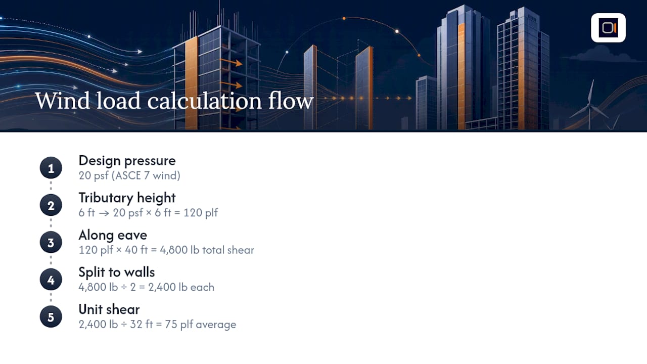
Picture a one-story wood-framed building, 32 feet wide by 40 feet long, with 9 foot wall height and a lightweight asphalt-shingle roof. Wind governs over seismic in this case, per an ASCE 7 wind pressure analysis, producing a design lateral pressure of 20 psf on the 32 foot end wall projection.
Step 1: Get the story shear. The tributary height for a single-story building with a 9 foot wall and a small roof overhang works out to roughly 6 feet of wall exposed to wind. Multiply 20 psf by 6 feet to get 120 plf of wind load along the 40 foot eave line, then multiply by the 40 foot building length: 120 plf × 40 ft = 4,800 lb of total diaphragm shear delivered to the two end shear wall lines.
Step 2: Distribute to the wall line. Split evenly, each 32 foot wall line resists 2,400 lb. Divide that by the 32 foot line length and you get an average unit shear v of 75 plf. That number is your starting point for both the segmented and perforated methods, and it is exactly the kind of figure a reviewer will scan for first.
Segmented method
The segmented (full-height) method assumes every shear-resisting segment runs uninterrupted from top plate to bottom plate, with openings simply ignored in the capacity calculation. Design generally follows five steps: determine loads, apply combinations, define geometry and materials, evaluate capacity and overturning, then verify serviceability.
-
Select 7/16 inch OSB with 8d common nails at 4 inches on center at panel edges, which SDPWS Table 4.3A lists at an allowable unit shear of roughly 260 plf for wind design.
-
Divide demand by capacity: 75 plf ÷ 260 plf = 0.29, meaning only about 29% of the wall line theoretically needs to be full-height sheathed.
-
Apply practical minimums (most jurisdictions want at least 4 feet of full-height segment per opening bay), and check that your actual full-height segments, summed, meet or exceed roughly 9.2 linear feet of the 32 foot line.
A worked comparison in Structure Magazine shows this segmented approach lining up closely with SDPWS engineered results, provided you use the same nailing and sheathing assumptions across both. If your architectural layout does not have 9.2 feet of clean full-height wall, you either upgrade the sheathing schedule or move to the perforated method.
Perforated method
The perforated method lets you use every foot of wall, including segments interrupted by windows and doors, by applying an opening-adjustment factor called Co. The perforated shear wall method computes wall capacity as Vwall = (v · Co) · ΣLi.
Say your 32 foot wall line has two full-height segments totaling 12 feet (ΣLi = 12 ft), separated by an 8 foot window opening and a 12 foot double-door opening. With that much opening area relative to full-height length, SDPWS tables put Co around 0.53.
- Vwall = (260 plf × 0.53) × 12 ft gives reduced capacity from that wall line, which may not meet demand depending on full-height segment lengths.
- Compare to demand: 2,400 lb needed versus 1,654 lb available means this configuration falls short and needs either more full-height footage or a higher shear rating.
- Recompute with 16 feet of full-height segment (Co rises to about 0.67 with less opening ratio): Vwall = (260 × 0.67) × 16 = 2,787 lb, which clears the 2,400 lb demand.
Pro Tip: Always recompute Co after adjusting your full-height segment lengths. It is not a fixed multiplier. Small changes in opening percentage swing Co enough to flip a design from failing to passing.
Once Co-adjusted capacity works, size collectors and anchorage for the maximum induced unit shear, not the average, as recommended in this Architectural Design training resource. The AWC perforated method sets vmax = v / Co, so here vmax = 75 / 0.67 = 112 plf. That governs your header and collector design, along with a bottom plate uplift check for uniform anchorage equal to vmax across the full-height segments.
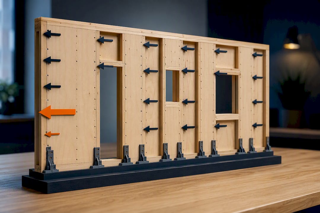
For chord tension and compression, take the overturning moment at each end post: T (or C) = (V · h) / L, where h is wall height and L the segment length between chords. This calculates hold-down demand to guide hardware sizing. Our guide on wood shear wall chord design walks through a similar 1,653 lb uplift case with hardware selection. When stacking a second story, sum overturning contributions from the story above into the lower hold-down before you select hardware, since skipping that summation is one of the most common errors reviewers flag.
Deflection check. SDPWS provides a four-term deflection equation combining bending, shear, nail slip, and anchorage rotation. A published perforated deflection example uses vmax in the anchorage term specifically, not average v, which trips up engineers who plug in the wrong shear value. Run the deflection number against your jurisdiction's story drift limit (commonly h/400 to h/200 depending on wall type and code edition) before calling the wall complete.
For a deeper look at pure full-height design without openings, see our segmented shear wall design guide, and for a longer perforated case study, our 24 foot perforated worked example walks the same Co logic across a wider wall line.
Reinforced Concrete Shear Wall Example: An ACI Hand-Check
Now switch materials. Assume a 10 foot tall, 20 foot long, 8 inch thick concrete shear wall in a low-rise building, carrying 40 kip of factored axial load (Pu) and 85 kip of factored lateral shear (Vu) from a combined wind and gravity load combination per IBC and ACI 318 provisions.
Flexural check. With vertical reinforcement of #5 bars at 12 inches on center each face, the wall's neutral axis depth and internal moment arm yield nominal moment capacity Mn which is compared against the factored demand Mu; the flexural check passes with some margin. That margin matters because boundary element detailing and lap splice placement often control real seismic performance more than the raw moment number suggests.
Shear capacity check. ACI 318 sets a nominal shear strength Vn from concrete and steel contributions. Using an 8 inch wall with #4 horizontal bars at 12 inches on center, Vn works out to approximately 145 kip. Applying the shear Φ factor per ACI 318 §21.2.4.1, typically 0.75 for shear-controlled walls without special seismic detailing, gives ΦVn = 0.75 × 145 = 108.75 kip.
- Verify Vu ≤ ΦVn: 85 kip ≤ 108.75 kip, so the wall passes shear with roughly 22% reserve capacity.
- Cross-check the upper limit: Vn cannot exceed 8√f'c times the gross wall area for the entire wall.pdf), and 10√f'c for individual piers, which for typical 3,000 to 4,000 psi concrete keeps most residential and low-rise walls well under the ceiling.
- Note the hw/ℓw ratio (here 10 ft / 20 ft = 0.5) since that ratio influences which αc coefficient applies in the concrete shear strength equation and affects whether the wall behaves more like a squat shear wall or a slender flexural wall.
Boundary elements. Once the neutral axis depth and strain conditions are checked against ACI thresholds, walls with higher axial load ratios or taller aspect ratios often trigger special boundary element requirements: confined reinforcement, closer tie spacing, and minimum development length at splices. Even when this wall does not strictly require special boundary elements under the load case shown, ACI worked examples consistently show that detailing at wall ends, not the bulk reinforcement ratio, is where designs actually fail inspection.
Final items to carry into your report: governing load combination, Pu and Vu values, Mn versus Mu comparison, Vn and ΦVn with the applied Φ factor, the hw/ℓw ratio used to select αc, and a one-line statement confirming boundary element requirements were checked and either triggered or waived with a reason.
What Goes Into a Permit-Ready Shear Wall Report
A reviewer should be able to check your numbers without calling you. Structure the report so nothing requires a phone call to explain.
- Inputs: building geometry, applicable code editions (IBC, ASCE 7, SDPWS/WFCM, or ACI 318), material properties, and full sheathing and fastener schedules.
- Outputs: story shear table, unit shear v and vmax, Vwall capacity, hold-down schedule with summed overturning from stories above, chord tension and compression values, and deflection or story drift results.
- Figures: a wall line plan, an elevation showing openings against full-height segments, and a table pairing each wall line to its sheathing choice and nailing pattern.
- Sign-off: governing equations referenced by clause number, and a signature block confirming the calculation set matches the drawings.
Pro Tip: Label every wall line on your elevation drawing exactly as it appears in your calculation table. A mismatched label between the drawing and the report is the single most common reason reviewers send back a resubmittal.
How to Reproduce These Numbers Without a Black Box
These examples came together the way any structural engineer would build them: standard SDPWS and ACI 318 clause references, load derivations per ASCE 7, and cross-checks against published worked examples rather than a single software output taken on faith. Always show these intermediate numbers in your own reports:
- Governing load combination and the resulting design shear
- Unit shear v, and vmax where the perforated method or collector design applies
- Co factor and how it was derived (tabulated or calculated)
- Hold-down summation across stories, not just the top-story value
- Story drift or deflection result against the applicable limit
ShearWise Pro organizes exactly these inputs for 1- and 2-story wood buildings, mapping wall lines, openings, hold-downs, and drift checks into a structured PDF. Even with automated output, reviewers expect governing equations and intermediate values on the page, not just a final pass/fail line.
What Actually Trips Up a Shear Wall Design in the Field
Most failures I've seen in reviewer comments trace back to field mismatches, not bad math: sheathing installed with the wrong nail spacing, bottom plate anchorage skipped where the drawing only showed hold-downs, or a collector sized for average shear instead of vmax. Reviewers want assumptions spelled out and hold-downs summed story by story, with drawing callouts matching your table labels exactly. Put a one-line verification summary on every page.
— Evalin
Reproduce These Examples Inside ShearWise Pro
Hand calculations prove the method, but rebuilding wall lines, hold-down sums, and drift checks from scratch on every project eats hours you could spend on design decisions. ShearWise Pro organizes shear wall calculations for 1- and 2-story wood-framed buildings: wall lines, openings, full-height segments, hold-down forces, transfer straps, roof inputs, and story drift checks all in one place, with a clean PDF export ready for permit submission.

You still get to decide what governing equations and intermediate numbers appear in the final report, which matters if your jurisdiction's reviewers expect to see Co, vmax, or ACI shear checks spelled out on the page rather than buried in a black box output. Walk through the platform with the ShearWise Pro tutorials to see how a full wall-line layout turns into a report in under an hour, then start a free trial and generate your first three reports at no cost.
Sources
- Shear Wall Design {Step-By-Step Guide}
- Perforated shear wall design (AWC)
- Wood shear wall design examples for wind (Structure Magazine)
- Reinforced concrete shear wall analysis/design (StructurePoint, ACI examples)
FAQ
How Do You Calculate a Shear Wall?
You determine the governing lateral load from wind or seismic combinations, distribute story shear to each wall line, compute unit shear v (and vmax for perforated walls with openings), then check that your chosen sheathing and hold-down schedule provides enough capacity and stiffness to satisfy drift limits.
Is 7/16 Inch OSB Sufficient for a Shear Wall?
Yes, in many wind-governed designs. Standard 7/16 inch OSB with 8d nails at 4 inches on center at panel edges provides roughly 260 plf of allowable unit shear per SDPWS tables, which is enough for many one-story residential wall lines, but you still need to verify it against your specific demand and nailing schedule.
What Is an Example of a Shear Wall?
A wood-framed exterior wall sheathed in OSB and connected with hold-downs at each end functions as a shear wall by resisting lateral wind or seismic forces through in-plane panel shear, as shown in the segmented and perforated calculations above. A reinforced concrete wall carrying both axial gravity load and lateral shear through flexural and shear reinforcement, checked against ACI 318, is a second common form.
How Do You Determine if a Wall Qualifies as a Shear Wall?
A wall qualifies once it has a continuous load path from roof or floor diaphragm through sheathing (or reinforced concrete) into a foundation, with hold-downs or reinforcement sized to resist overturning and a documented unit shear capacity meeting or exceeding the demand from your load calculation. Tools like ShearWise Pro flag wall lines automatically once wall geometry and openings are entered, which speeds up this qualification step for wood buildings.
Do You Need Different Calculations for Multi-Story Buildings?
Yes. Each story's shear accumulates downward, so a second-story wall line's hold-down demand must be summed with the story above before you size the ground-floor hardware, and story drift checks apply separately at each level per SDPWS deflection equations.