
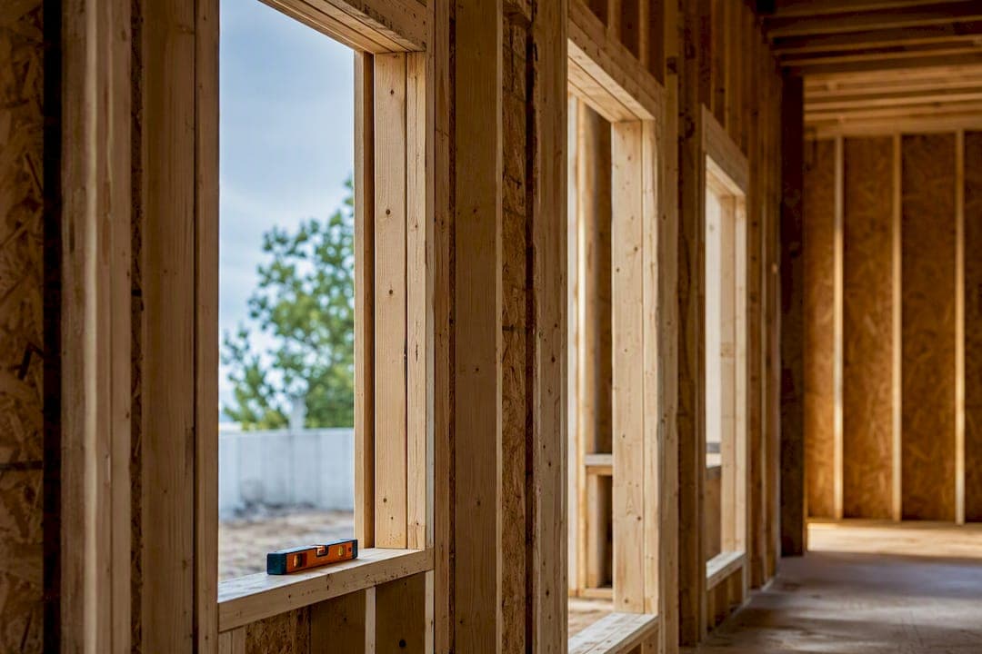
Wood structural panel shear walls commonly have a maximum aspect ratio around 3.5:1, with a practical seismic design baseline near 2:1. Once a segment's height-to-width ratio passes 2:1, you multiply its nominal shear capacity by an adjustment factor related to 2·bs/h, and segments exceeding the maximum ratio are excluded from the capacity sum. The controlling references are the AWC Special Design Provisions for Wind and Seismic (SDPWS), the IRC, and the perforated shear wall provisions AWC publishes alongside them.
TL;DR:
- Shear wall segments exceeding a 2:1 height-to-width ratio require capacity reduction calculations, with segments over 3.5:1 contributing nothing to the shear capacity.
- Blocked walls can conform to a 3.5:1 ratio with adjustments, while unblocked walls are limited to 2:1, necessitating careful measurement of sheathing width.
- Narrow piers at high ratios, especially above 4:1, can significantly reduce overall wall performance and must be excluded from capacity sums.
- Accurate documentation of segment ratios, adjustments, and exclusions during plan review is essential to meet code requirements and ensure proper shear capacity.
- Automated tools like ShearWise Pro can streamline these calculations, improve accuracy, and generate permit-ready documentation automatically.
Table of Contents
- Understanding Shear Wall Aspect Ratio Code Limits
- How to Apply the Aspect-Ratio Adjustment Formula
- Perforated Shear Walls: Adjusting Segment Widths Around Openings
- Blocking Requirements and Minimum Sheathing Width Checks
- Design Checklist and Worked Example for Vwall
- Plan-Check Traps and Documenting Your Aspect-Ratio Work
- ShearWise Pro: Automate Aspect-Ratio Checks and Skip the Spreadsheet Rebuild
- Sources
Understanding Shear Wall Aspect Ratio Code Limits
The AWC's guidance on maximum shear wall aspect ratios sets 3.5:1 as the ceiling for blocked wood structural panel shear walls. For an 8-foot-tall wall, that ratio translates into a minimum full-height sheathing width that is approximately consistent with published guidance, such as around 27.5 inches. Fall below that width and the segment no longer qualifies as a full-height shear-resisting element, no matter how well it's nailed.
The distinction between 2:1 and 3.5:1 comes down to loading type and blocking status. SDPWS Table 4.3.4 and IRC Table 2305.3.3 both list maximum ratios that vary by sheathing material and whether the wall is blocked:
- Blocked wood structural panel walls: maximum 3.5:1, with the 2·bs/h multiplier required above 2:1 for seismic design.
- Unblocked wood structural panel walls: typically capped at 2:1, with no allowance to push further through adjustment.
- Fiberboard, particleboard, and gypsum panels: generally held to tighter limits, often 1.5:1 or 2:1 depending on the specific table entry.
- Wind-governed walls: some jurisdictions permit the higher ratio without the same adjustment burden that seismic design imposes.
Before you finalize a wall line, pull the actual table for your assembly type rather than assuming the 3.5:1 number applies universally. UpCodes' summary of shear wall aspect ratio provisions is a fast way to cross-check IRC language against your specific panel and blocking condition.
How to Apply the Aspect-Ratio Adjustment Formula
Once you know a segment's height-to-width ratio exceeds 2:1, the code doesn't let you use its tabulated unit shear value at face value. You have to knock it down.
- Calculate h/bs for the segment in question, where h is wall height and bs is the segment width.
- If h/bs > 2:1, multiply the tabulated nominal unit shear by 2·bs/h. This is the core reduction WoodWorks describes for multiple shear walls in a line, and it applies the same way whether you're checking a single wall or a perforated line.
- If h/bs > 3.5:1, the segment contributes nothing. Drop it from ΣLi.
- Insert the adjusted unit shear into V = v·ΣLi·Co, where v is your adjusted (or unadjusted, if the ratio is under 2:1) unit shear, ΣLi is the sum of qualifying segment lengths, and Co is the opening-adjustment factor.
The multiplier matters more than most designers expect. A segment at a 3:1 ratio isn't marginally weaker than one at 2:1. It's operating at roughly two thirds of its tabulated capacity once you run the math, because the 2·bs/h factor scales linearly with how far past 2:1 you've pushed the geometry.
Some older references apply a separate factor for fiberboard sheathing, though that adjustment isn't tied to a current citable table the way the wood structural panel multiplier is. Treat it as background context rather than a number to design against unless your local code explicitly calls it out. For a deeper walkthrough of how the reduced capacity plays into a full wall line, see ShearWise Pro's explainer on shear wall ratio.
Perforated Shear Walls: Adjusting Segment Widths Around Openings
Perforated (segmented) shear walls introduce a wrinkle: you're not evaluating one continuous panel, you're evaluating a series of full-height segments interrupted by door and window openings. Each segment gets its own aspect-ratio check.
Segment width, or bs, is measured as the clear horizontal length of full-height sheathing between openings or at the wall's end. UpCodes' definition of perforated shear wall segment width makes clear this measurement excludes any interruption, however small, that breaks the full-height sheathing plane.
Once you've measured every segment:
- Flag any segment where h/bs exceeds 2:1. That segment's length gets multiplied by 2·bs/h before it enters ΣLi.
- Exclude any segment where h/bs exceeds 3.5:1 outright. It contributes zero length to the sum.
- Check that end segments meet minimum width requirements, since narrow end piers are the most common place this rule bites unexpectedly.
- Verify collectors and blocking are detailed consistently across all segments in the line, not just the widest one.
The AWC's perforated shear wall design guidance walks through this measurement process with figures worth keeping on hand during layout.
Pro Tip: A single narrow pier at a 4:1 ratio doesn't just lose capacity, it can drag down the entire wall line's percent full-height sheathing, which then lowers your Co factor for every other segment in the same line.
Blocking Requirements and Minimum Sheathing Width Checks
Blocking status changes which aspect-ratio ceiling applies. Blocked walls, where all panel edges land on framing, get access to the full 3.5:1 allowance with the adjustment factor. Unblocked walls generally don't get that flexibility and stay capped at 2:1 without relief.
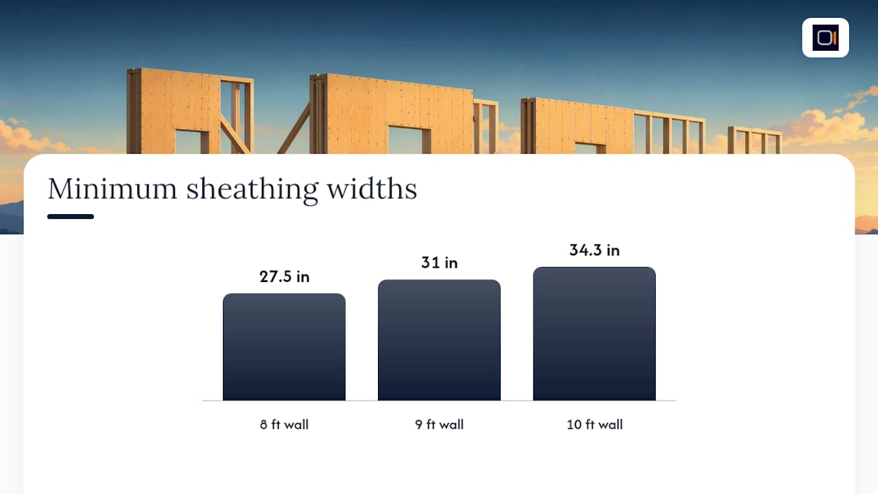
For a quick field check on an 8-foot-tall wall targeting the 3.5:1 maximum, you need at least 27.5 inches of continuous full-height sheathing per segment, a figure straight from AWC's own FAQ. Scale that proportionally for other wall heights: a 9-foot wall needs roughly 31 inches, a 10-foot wall closer to 34.3 inches, assuming you're holding the same 3.5:1 target.
Run these checks during plan review, not after:
- Confirm blocking is called out on the framing plan everywhere a 3.5:1 ratio is claimed.
- Verify nailing schedules match the sheathing type assumed in your capacity table lookup.
- Measure clear pier heights consistently, top of sill to bottom of top plate or header, not to a rough opening edge.
- Cross-check that no full-height segment narrower than your calculated minimum got sheathed as though it qualified.
Design Checklist and Worked Example for Vwall
Here's the sequence to run on every shear wall line before you commit to a capacity number:
- Measure every full-height segment width (bs) and total wall height (h).
- Classify each segment: does h/bs fall under 2:1, between 2:1 and 3.5:1, or over 3.5:1?
- For segments over 2:1, compute the 2·bs/h multiplier.
- Recompute ΣLi using adjusted lengths, dropping anything over 3.5:1.
- Pull unit shear (v) from your governing table and the Co factor from percent full-height sheathing.
- Multiply v × ΣLi × Co to get Vwall.
Worked example: Consider an 8-foot wall line with two full-height segments: one 48 inches wide, one 20 inches wide.
Segment A stays at full value since it sits right at the 2:1 threshold. Segment B exceeds 3.5:1, so it contributes nothing to ΣLi regardless of how well it's nailed. ΣLi becomes 48 inches, not 68. If your tabulated unit shear is 260 plf and your percent full-height sheathing calculation yields a Co of 0.85, Vwall = 260 × 4.0 ft × 0.85 = 884 pounds. Drop Segment B from the layout and that number would look identical, since it wasn't contributing anyway, a fact worth catching before construction rather than during a plan-check rejection.
For a longer version of this kind of calculation across a full 24-foot wall line, ShearWise Pro's perforated shear wall worked example walks through multiple segments and openings in sequence.
Plan-Check Traps and Documenting Your Aspect-Ratio Work
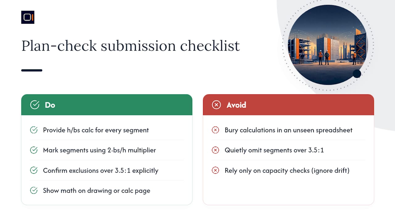
Reviewers almost always ask for the same three things: your h/bs calculation for every segment, an explicit note on which segments got the 2·bs/h multiplier, and confirmation that anything over 3.5:1 was excluded rather than quietly forgotten. Show that math on the drawing or calc page itself, not buried in a spreadsheet nobody submitted.
Aspect ratio isn't purely a strength check, either. It affects stiffness and drift, so a wall line that passes shear capacity but leans heavily on narrow piers can still underperform for story drift. Document that reasoning alongside your capacity numbers, and reviewers tend to move faster.
— Evalin
ShearWise Pro: Automate Aspect-Ratio Checks and Skip the Spreadsheet Rebuild
Running the h/bs classification, the 2·bs/h multiplier, and the ΣLi exclusion by hand across a full wall line eats time you'd rather spend on layout decisions. A shear wall calculator focused on 1-story and 2-story wood-framed buildings can help fill that gap without requiring a general structural suite that needs full configuration.

A platform that organizes wall lines, tracks openings and full-height segments, computes hold-down forces and transfer strap requirements, and applies the aspect-ratio adjustments this article walks through automatically can save time and improve accuracy. Every wall line maps to the same checklist covered above: measure, classify, adjust, recompute, multiply. The output can include a clean PDF report formatted for permit and review coordination, making required documentation readily available. See what that report looks like on the sample ShearWise report page, or start with the ShearWise Pro shear wall calculator and run your next wall line through it before your next submittal deadline.
Sources
- What is the maximum shear wall aspect ratio for various wood wall assemblies? - American Wood Council
- Calculating the capacity of multiple shear walls in a line - WoodWorks
- Shear wall aspect ratios - UpCodes