
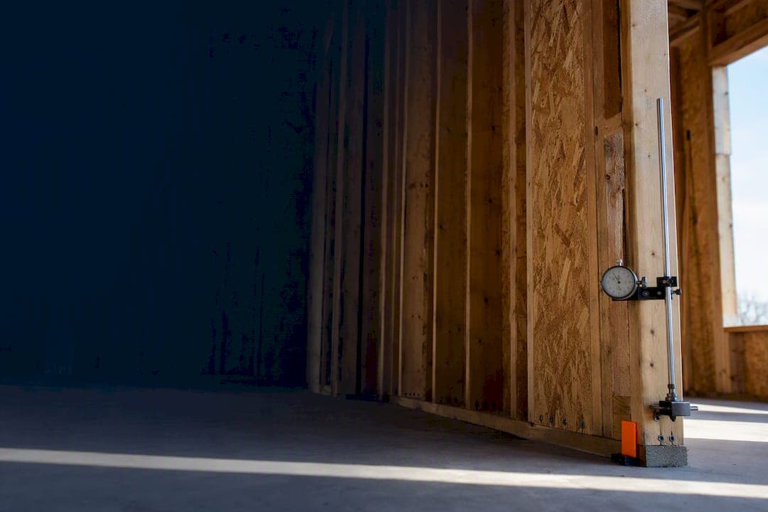
AWC's Special Design Provisions for Wind and Seismic (SDPWS) governs shear wall deflection calculations, and IBC 2305.3 requires that you calculate it that way. Total deflection, Δsw, breaks into four parts: bending of the end posts (chords), panel shear deformation, nail or staple slip, and anchorage elongation. Add those four terms together and you have the deflection that gets compared against story drift limits. The next section shows exactly where in the code to find each variable.
TL;DR:
- The shear wall deflection calculation must follow SDPWS formulas, referencing the specific edition adopted by your jurisdiction to ensure accuracy.
- The full deflection includes four parts: bending of end posts, panel shear deformation, nail slip, and anchorage elongation, with nail slip and anchorage often dominating the total.
- For perforated walls, the unit shear is adjusted using effective length, requiring wall segmentation and recalculated shear capacities for accurate deflection estimates.
- Using conservative Gt, en, and da values, especially when test data is unavailable, helps avoid underestimating actual deflections in design.
- Automated software tools streamline the calculation and documentation process, reducing review delays and producing permit-ready reports based on the same code-backed formulas.
Table of Contents
- Which Codes Govern Shear Wall Deflection Calculations?
- What Is the Full Δsw Formula and What Do the Terms Mean?
- Where Do You Find Gt, En, and Da Values?
- How Do Openings Change the Deflection Calculation?
- Worked Example: Calculating Deflection for a Typical Wall
- How Does Deflection Relate to Story Drift Limits?
- What Detailing Mistakes Cause the Most Review Comments?
- Balancing Conservative Design With Project Constraints
- Get Permit-Ready Shear Wall Reports Faster
- Sources
- FAQ
Which Codes Govern Shear Wall Deflection Calculations?
IBC 2305.3 sends you straight to AWC SDPWS for calculating shear wall deflection in wood-frame buildings. It doesn't reinvent the formula. It defers to it, which means your calculation package needs to reference the SDPWS edition your jurisdiction has actually adopted, not whichever one happens to sit on your desk.
Inside SDPWS, Section 4.3.2 covers deflection for blocked wood structural panel shear walls, with related clauses addressing perforated wall provisions. A few things to keep straight before you start plugging numbers into a spreadsheet:
- The simplified equation in SDPWS 4.3.2 is a permitted method, not the only method.
- SDPWS also allows a rational analysis when the simplified equation understates real wall behavior, particularly for unusual aspect ratios or mixed sheathing.
- Different code cycles (2018, 2021, 2024 IBC) reference different SDPWS editions, and table values have shifted between editions.
- Always confirm which edition your local building department has adopted before citing a table value in your report.
What Is the Full Δsw Formula and What Do the Terms Mean?
The canonical equation, as APA documents in its technical literature, sums four deformation mechanisms:
Δsw = 8vh³/(EAb) + vh/(1000Gt) + 0.75h·en + (h/b)·da
Here's what each symbol means and why it belongs in the equation:
- 8vh³/(EAb), the bending term, models the end posts (chords) flexing under load. v is unit shear (lb/ft), h is wall height, E is the modulus of elasticity of the chord material, A is chord cross-sectional area, and b is wall length. Because h is cubed, taller narrow walls are disproportionately sensitive to chord stiffness.
- vh/(1000Gt), the panel shear term, captures how the sheathing itself distorts under unit shear. Gt is apparent shear stiffness, a table-derived value covered in the next section.
- 0.75h·en, the nail slip term, accounts for the sheathing fasteners rotating and slipping under load. en is nail or staple slip in inches, and the 0.75 coefficient is empirical, calibrated from cyclic test data rather than derived from first principles.
- (h/b)·da, the anchorage term, aggregates elongation at hold-downs, anchor rods, and connector hardware. da is total anchorage elongation in inches.
Where Do You Find Gt, En, and Da Values?
Apparent shear stiffness (Gt) values live in SDPWS tables and in APA's supporting technical documents, organized by panel grade, thickness, and nailing schedule. When a wall is sheathed on both faces with identical panels and fastening, combined stiffness is simply additive: Gcombined = G1 + G2. Mixed sheathing on opposite faces requires more care, since the two sides won't share the same load path stiffness.
Nail and staple slip (en) comes from the same table families, though values vary with fastener diameter, panel thickness, and moisture content at installation. A few practical notes:
- Use manufacturer test data for engineered fasteners rather than defaulting to generic table values when a specific product is specified.
- Where no test data exists, select the more conservative (higher slip) value in the applicable table column.
- Anchorage elongation (da) should sum hold-down device elongation, anchor rod stretch, and connector deformation, not just bolt hole slop.
Pro Tip: Never assume da equals zero because the hold-down looks "stiff." Rod elongation alone can exceed nail slip on tall, heavily loaded walls, and skipping it produces a deflection number that looks better than reality.
For complex load paths, unusual geometry, or critical collectors, running a full rational analysis beats forcing the simplified equation to fit a case it wasn't calibrated for.
How Do Openings Change the Deflection Calculation?
Perforated shear walls, meaning walls with door and window openings that aren't individually designed as full-height segments, require an adjustment before you can even apply the Δsw equation. The code doesn't let you use nominal unit shear directly. Instead, v in the formula becomes vmax, the adjusted unit shear that accounts for the reduced effective length caused by the openings.
- Effective length (LL) is calculated per SDPWS perforated wall provisions, using the sum of full-height sheathed segment lengths relative to total wall length.
- When openings are large or irregular, it's often cleaner to split the wall into discrete full-height segments and run each one separately rather than forcing a single perforated calculation.
- For walls sheathed identically on both sides, combined stiffness rules still apply, but Vs (shear capacity) and Gt need to be recalculated for the reduced effective segments, not the gross wall length.
ShearWise Pro's worked example of a perforated shear wall walks through this exact segment-splitting logic for a 24-foot wall with two openings.
Worked Example: Calculating Deflection for a Typical Wall
Take a single-story wall, 8 feet tall, 12 feet long, sheathed with 15/32-inch structural panels, 8d common nails at 4 inches on center at panel edges. Design unit shear v = 260 lb/ft. End posts are doubled 2x6 Douglas Fir-Larch, E = 1,600,000 psi, A = 12.375 in².
- Bending term: 8(260)(8)³/[(1,600,000)(12.375)(12)] = 133,120/(237,600,000) = 0.00056 in.
- Panel shear term: Using Gt = 21,000 lb/in from the applicable SDPWS table, vh/(1000Gt) = (260)(8)/(1000×21,000) = 2,080/21,000,000 = 0.0001 in.
- Nail slip term: With en = 0.02 in at this shear level, 0.75(8)(0.02) = 0.12 in.
- Anchorage term: With da = 0.15 in (hold-down elongation plus rod stretch), (8/12)(0.15) = 0.10 in.
Δsw = 0.00056 + 0.0001 + 0.12 + 0.10 ≈ 0.22 inches
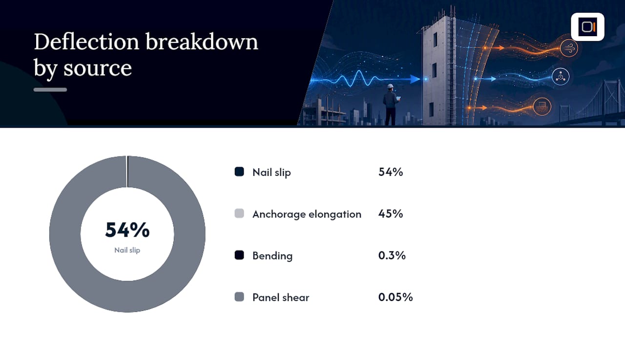
Nail slip and anchorage elongation dominate this result, together accounting for nearly all of the total. That's the pattern you'll see on most light-frame walls: bending and panel shear often contribute less to deflection than fastener and hardware deformation.
How Does Deflection Relate to Story Drift Limits?
Story drift is Δsw divided by story height, usually expressed as a percentage. ASCE 7 and IBC set allowable drift limits that vary by risk category and seismic design category, and your calculated Δsw needs to fit inside whatever limit applies to the specific structure.
When your number comes in over the limit, you have a short list of real options:
- Redistribute shear to stiffer wall lines rather than uniformly loading every wall.
- Increase panel thickness or tighten the nailing schedule to raise Gt and lower the shear demand per linear foot.
- Upgrade hold-down hardware to reduce da, particularly on tall, narrow walls where anchorage dominates.
- Add length to full-height sheathed segments if the wall is perforated and effective length is the bottleneck.
As a quick preliminary heuristic, walls with height-to-length ratios higher than 2:1 tend to accumulate deflection fast enough that a rational check early in design saves rework later.
What Detailing Mistakes Cause the Most Review Comments?
Plan reviewers see the same handful of problems repeatedly, and most trace back to a handful of avoidable choices.
- Top-plate discontinuities: sheathing is not a valid chord splice. WoodWorks guidance is explicit that discontinuous top plates need a mechanical splice, blocking, or a continuous collector, documented on the drawings.
- Nailing mismatches: a nailing schedule shown on the framing plan that doesn't match what's assumed in the shear wall chord calculation invalidates both the Gt value and the shear capacity.
- Hold-down detailing: stack-up tolerances and combined uplift paths through multiple stories can quietly add inches of da if nobody checks the full connector chain.
Pro Tip: Document every table reference and assumption directly in your calculation report. Reviewers ask fewer questions when they can see exactly which SDPWS table and edition produced your Gt and en values.
Balancing Conservative Design With Project Constraints
Rational analysis earns its extra hours on complex perforated walls and critical collectors, not on routine 8 foot walls with clean geometry. Picking the conservative table value every time drives up connector costs fast, and most of that cost buys you nothing on a wall that was never close to the drift limit. What actually saves time on review is a calculation report that shows its work: table sources, edition numbers, and the reasoning behind every substitution, organized the same way every time.
— Evalin
Get Permit-Ready Shear Wall Reports Faster
Running the Δsw equation by hand for every wall line on a multi-wall project eats hours you'd rather spend on design decisions. Some shear wall calculator platforms organize wall lines, openings, full-height segments, hold-down forces, and story drift checks into one workflow, then export clean PDF reports built for permit review.

The platform handles the repetitive arithmetic (chord bending, panel shear, nail slip, and anchorage elongation) using the same SDPWS-backed shear wall calculator logic covered in this article, so your report shows the component breakdown a reviewer expects to see rather than a single unexplained number. It's built specifically for 1 and 2 story wood-framed projects, which means no wasted screen space on load cases you'll never use. If you want to see the workflow before committing, the tutorial library walks through a full wall line setup from geometry to finished PDF. Start with a free trial that includes three watermarked reports through the shear wall software page and see how it compares to hand calculations on your next project.
Sources
- IBC 2305.3 Shear wall deflection (code reference)
- Wood Structural Panel Shear Wall Deflection Formula — APA
FAQ
When Should You Run a Rational Analysis Instead of the Simplified Equation?
Use rational analysis for walls with irregular perforations, unusual aspect ratios, or critical collectors where the simplified SDPWS equation's assumptions don't hold up well.
How Do You Estimate Anchorage Elongation Without Test Data?
Sum hold-down device elongation, anchor rod stretch, and connector deformation, using manufacturer data where available and conservative table values when it isn't.
Are Narrow Shear Walls Still Allowed Under Current Codes?
Yes, but narrow walls carry stricter aspect ratio limits and drift scrutiny since attention to deflection tightened after the 1994 Northridge earthquake, so check current SDPWS aspect ratio tables before finalizing a narrow segment.
What's the Difference Between Gt and Combined Stiffness?
Gt is the apparent shear stiffness for a single sheathed face; combined stiffness for identical two-sided sheathing is the sum of both faces' Gt values.
Can Software Replace Hand Calculations for Shear Wall Deflection?
A dedicated calculator like ShearWise Pro applies the same SDPWS-based Δsw equation but organizes wall lines, hold-downs, and drift checks into a single permit-ready report.