
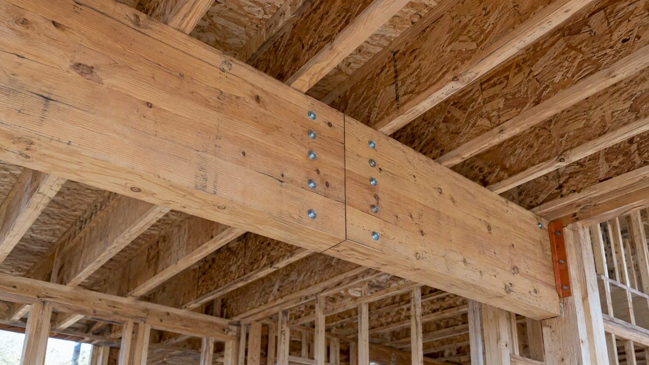
Under the IBC, a collector (also called a drag strut) is the load-path member that gathers diaphragm shear and transfers it to vertical force-resisting elements. Collectors are required when the diaphragm cannot directly deliver shear to those elements, a condition typically triggered by openings, offsets, short shear walls, or diaphragm discontinuities. Confirming the condition means opening the IBC, ASCE 7, and the AWC SDPWS together.
TL;DR:
- For Seismic Design Categories C through F, ASCE 7 generally applies the system overstrength factor to collectors, splices, and connections; wind design does not.
- Design collectors for tension and compression, combined axial and flexural demand when they carry gravity loads, and continuity through every splice and bearing point.
- Show factored or nominal drag force in pounds per foot at each splice on plans, plus connector capacities, fastener patterns, bearing details, and inspection access.
- A strap carries tension but cannot resist compression alone; drag truss submittals must state force, bearing conditions, and required reactions, not rely on catalog assumptions.
Table of Contents
- What the IBC and referenced standards say about collectors
- Design loads and overstrength: wind, seismic, and amplification factors
- Sizing, splices, and connection detailing: a compliance checklist
- Common collector types and field detailing
- Documenting collectors for permit sets and shop drawings
- Coordinating collectors on 1 and 2 story wood projects
- Generate permit-ready collector reports with ShearWise Pro
- FAQ
- Sources
What the IBC and referenced standards say about collectors
The IBC defines a collector as a diaphragm or shear wall boundary element, parallel to the applied load, that collects and transfers diaphragm shear forces to the vertical elements of the lateral force-resisting system. That definition matters at the plan-review stage because it tells you a collector is not optional detailing. It is a required structural element whenever the diaphragm's shear cannot reach a shear wall or frame directly.
A few plan conditions should prompt you to check for a collector requirement:
- A large opening interrupts a shear wall line or diaphragm edge.
- A shear wall is offset from the diaphragm edge or from the wall below it.
- A re-entrant corner or irregular diaphragm shape creates a discontinuity.
- A short wall segment carries high unit shear relative to its length.
Once a collector is confirmed, ASCE 7 governs the load and load combination requirements, the AWC SDPWS governs wood member and connection capacities, and ANSI/TPI applies when the collector is built into a truss rather than a wall plate.
Design loads and overstrength: wind, seismic, and amplification factors
Collector design starts with the controlling lateral load, wind or seismic, run through the applicable ASCE 7 load combinations. In most 1 and 2 story wood buildings, seismic demand governs the collector itself, while wind can still control the shear wall it feeds. The distinction matters because seismic design introduces a factor that wind design does not.
When Seismic Design Categories C through F apply, ASCE 7 generally requires collector elements, splices, and their connections to be designed using load combinations that include the system overstrength factor. That factor amplifies the force a collector and its splices must carry well above the nominal diaphragm shear, which is why a collector sized only for code-level seismic force often fails at the splice under the amplified case.

A collector splice sized for nominal shear but not for overstrength is a common source of permit rejection and field rework, since splices and connections carry the amplified force, not the baseline demand.
A few items belong on every collector calculation sheet:
- State whether the reported force is factored (includes overstrength) or nominal.
- Include any vertical dead and live load contribution when sizing bolted or nailed connections at bearing points.
- Check both tension and compression cases, since wind and seismic reverse direction.
Sizing, splices, and connection detailing: a compliance checklist
Collector design is a combined axial and flexural problem whenever the member also carries gravity load, such as a top plate doubling as a header bearing point. Continuity is the governing principle: a collector that is strong at midspan but interrupted at a splice or a bearing wall has no real capacity, because the splice is the practical weak point in most collector failures, not the member itself.
Use this sequence when detailing a collector for permit submission:
- Confirm the controlling force (plf) and whether it is factored or nominal.
- Size the member for combined axial and flexural demand at the critical section.
- Detail each splice location with the specific strap, plate, or connector and its capacity.
- Specify the nailing schedule or fastener pattern at each connection, referencing SDPWS values rather than generic notes.
- Show anchor and bearing details where the collector lands on a foundation or beam.
- Flag any concealed splice location that requires inspection before cover.
Pro Tip: Call out the drag force in plf directly on the framing plan at each splice, not just in the calculation package, so the framer and inspector see the same number you designed to.
Shop-drawing review should confirm that the truss manufacturer or component supplier used the same force and bearing assumptions you specified, not a generic reaction pulled from a catalog span table.
Common collector types and field detailing
Three collector types cover most 1 and 2 story wood projects, and each carries its own detailing risk.
- Top-plate collectors: typically doubled plates with blocking at panel edges; when an opening breaks the continuous plate line, a strap or distinct collector member must bridge the gap.
- Strap and ledger collectors: straps handle tension well but need a separate bearing or blocking detail for compression, since a strap alone cannot push.
- Drag trusses: the truss designer needs the drag force, bearing condition, and specified reactions (R, RL, or U) called out explicitly, because truss submittals are often missing this data when the design professional assumes the truss plant will infer it.
A quick field check: trace the nailing pattern from the diaphragm sheathing into the collector and from the collector into the shear wall or strap. A gap anywhere in that nailing path breaks the load path even when every member is correctly sized.
Documenting collectors for permit sets and shop drawings
Plan reviewers and truss manufacturers need a short, specific set of callouts to approve collector designs without a resubmittal cycle.
- State the drag force in plf at each collector segment, and note whether it is factored or nominal.
- Locate every collector, splice, and connection explicitly on the framing plan, not just in the calculation narrative.
- Include fastener schedules, strap specifications, and truss reaction notation on shop drawings submitted for review.
- Note any concealed splice that requires inspection access before the next framing stage covers it.
Coordinating collectors on 1 and 2 story wood projects
Calling out plf and splice locations directly in the framing notes, not buried in a calculation PDF, cuts down field questions and resubmittal cycles. Reviewing validation examples and permit-ready checklists before submission, such as those in our Validation Library, helps confirm the collector documentation matches what reviewers expect to see.
— Evalin
Generate permit-ready collector reports with ShearWise Pro
We built our platform around the exact documentation this article describes: wall lines, openings, hold-downs, transfer straps, and collector forces, organized into a clean PDF report a reviewer can approve on the first pass. For 1 and 2 story wood-framed projects, that means less time reformatting calculations into permit-ready layouts and more time on design decisions.

- Start with the Three-Report Trial, three watermarked reports at no cost, to see the report format firsthand.
- Move to Professional Monthly or Professional Annual once you need ongoing project output.
- Review the full feature set for wood-framed residential projects before you commit.
Our shear wall calculator and report platform is built specifically for the collector, hold-down, and transfer documentation this article walks through.
FAQ
What are IBC requirements?
The IBC sets minimum design, construction, and safety requirements for buildings, including the structural provisions that govern lateral force-resisting systems such as diaphragms, shear walls, and collectors. For collector elements specifically, the code's definition ties directly to ASCE 7 for loads and the AWC SDPWS for wood member and connection capacities.
When does a diaphragm need a collector?
A collector is needed whenever the diaphragm cannot deliver shear directly into a vertical resisting element below it. Common triggers include large openings, wall offsets, re-entrant corners, and short shear wall segments that interrupt the direct load path.
Does seismic design always require the overstrength factor on collectors?
Not always. In Seismic Design Categories C through F, ASCE 7 generally requires collector elements, splices, and connections to be designed with the system overstrength factor applied, which increases demand beyond the nominal diaphragm shear.
What should a drag truss submittal show?
A drag truss submittal should state the drag force in plf, whether that force is factored, the bearing condition, and the specified reactions the truss must carry. Structure Magazine notes that missing this data is a common source of confusion between design professionals and truss manufacturers.
Can a top plate serve as a collector?
A continuous top plate can serve as a collector in many wood-framed walls, but when an opening or plan irregularity breaks that continuity, a distinct strap or drag truss is usually needed to carry both tension and compression across the gap.
Sources
Review the IBC definitions chapter, the ATC/FEMA briefing on diaphragm force transfer, and the AWC SDPWS and ANSI/TPI references for nailing and truss shop expectations. For roof diaphragm interfaces, see metal roof code requirements.
- International Building Code (IBC) — Chapter 2 definitions
- Architecturecourses
- Drag trusses — Structure Magazine
- Lateral force collectors for seismic and wind-resistant framing — JLC Online