
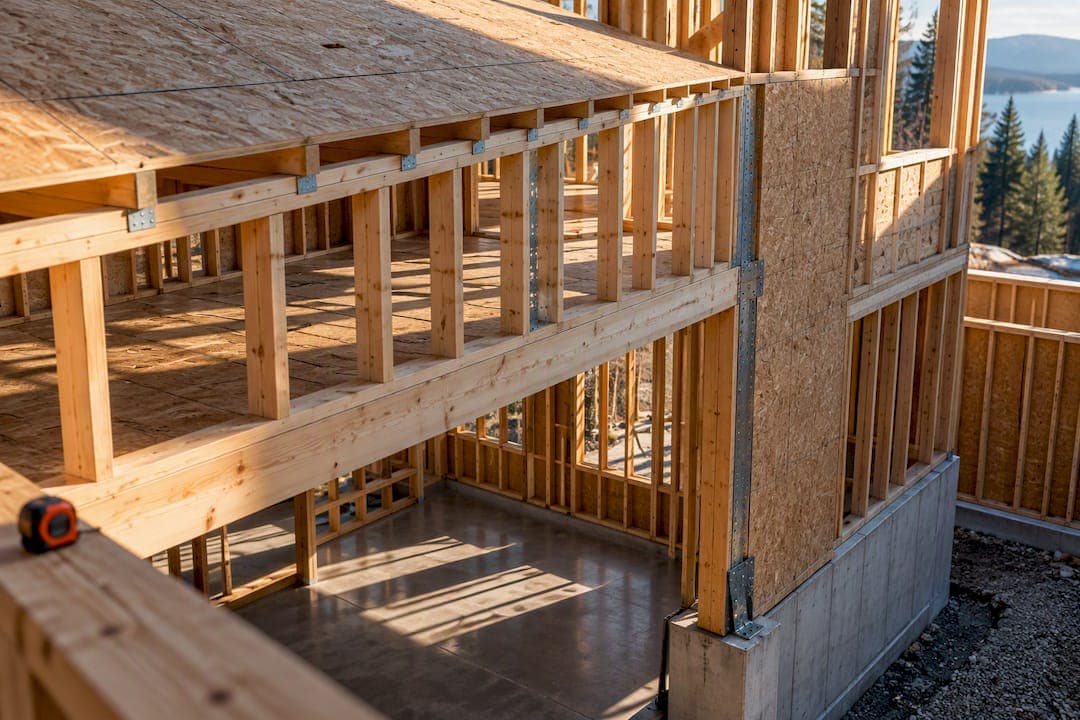
Diaphragm shear transfer is the process by which a diaphragm collects lateral inertia forces and delivers them into the vertical elements of the lateral system through connections designed to carry that tributary load. Code provisions require every diaphragm-to-wall connection to develop the calculated transfer demand, referred to as Vd, at the interface where the diaphragm meets a shear wall or collector. This guide walks through the governing formulas, modeling choices, material-specific mechanisms, and the detailing checks you need before a set goes out for review.
TL;DR:
- Connections must develop the full tributary shear demand Vd, which can be calculated using seismic parameters or unit shear times span length, and undersizing a single anchor compromises the load path.
- Diaphragms can be modeled as rigid, semi-rigid, or flexible, with shear distribution based on that idealization, but best practice is to run both and design to the envelope of results.
- Proper shear transfer involves specific mechanisms like collectors, chords, shear friction, and transfer straps, with detailed attention needed around openings to maintain continuous sheathing and accurate load paths.
- Ensure all wall line load paths, connection details, and openings are verified through thorough calculations and documentation before issuing construction drawings.
- Software modeling should include both rigid and flexible assumptions, with section cuts at each wall line to confirm load distribution aligns with the intended diaphragm behavior.
Table of Contents
- Diaphragm anatomy and the continuous load path
- Code formulas that govern diaphragm shear transfer
- How diaphragm modeling changes shear distribution
- Mechanisms that physically move shear into the walls
- Force Transfer Around Openings for wood diaphragms
- Concrete diaphragm and collector detailing
- Design and detailing checklist before you issue drawings
- Author notes and where the worked examples live
- Inspecting and maintaining diaphragm shear transfer elements
- Software tools and modeling practices for diaphragm analysis
- Three mistakes that keep showing up in review
- A faster path through the calculations with ShearWise Pro
- Sources
- FAQ
Diaphragm anatomy and the continuous load path
A diaphragm is the horizontal or sloped structural surface, typically a roof or floor, that collects wind and seismic forces and routes them to the vertical lateral system. A shear wall receives that force and sends it down to the foundation. A collector, sometimes called a drag strut, extends the diaphragm's reach to a wall that doesn't span the full building width. A chord resists the tension and compression that develop along the diaphragm's edges, acting like the flange of a horizontal beam.
The load path only works if each piece connects to the next. Diaphragm shear gets apportioned to vertical elements based on their tributary area or their relative stiffness, depending on the modeling approach, and every transfer point along that path needs a connection sized for its share.
Two conditions push this analysis harder than a typical layout:
- Podium diaphragms, where a wood diaphragm sits on a concrete podium and must transfer large forces into a stiffer material below.
- Plane changes, where the diaphragm shifts elevation or direction and forces have to redirect through collectors rather than travel straight into a wall.
Code formulas that govern diaphragm shear transfer
The transfer demand at any diaphragm connection is expressed as Vd, and codes give two common ways to calculate it. The first ties the demand to seismic design parameters: 1.2 SD1 Cp Wd, where SD1 is the design spectral acceleration parameter, Cp is a diaphragm design coefficient, and Wd is the weight of the diaphragm tributary to the connection under review. The second expresses demand directly as a unit shear times a length: v_d D, where v_d is the diaphragm unit shear and D is the depth of the diaphragm span carrying that shear into the wall.

UpCodes A604.6.1 sets out both expressions and requires that every diaphragm connection be capable of developing whichever tributary Vd governs at that location, not an averaged or reduced value.
Every diaphragm-to-wall connection must be sized to develop its full tributary Vd, per UpCodes A604.6.1, which means undersizing even one anchor or strap breaks the load path at that point regardless of how the rest of the diaphragm performs.
Anchor detailing carries its own rules. UpCodes A604.6.2 sets maximum anchor spacing at 6 feet along a wall, requires a minimum of two anchors on short wall segments, and specifies washer and nut bearing requirements against wood or steel. SDPWS provisions govern how diaphragm shear gets distributed into those anchors, and for concrete interfaces, ACI shear-friction assumptions apply instead.
How diaphragm modeling changes shear distribution
Diaphragms get idealized three ways: rigid, semi-rigid, or flexible, and the choice changes how much shear each vertical element receives. A rigid diaphragm distributes shear in proportion to the stiffness of the vertical elements, the same equal-deflection logic used for rigid floor diaphragms in concrete and steel buildings. A flexible diaphragm distributes shear by tributary area instead, treating each wall as an independent support. Semi-rigid modeling sits between the two and usually reflects real wood and light-gauge diaphragm behavior more closely, though it takes more modeling effort to set up.
SDPWS permits a simplified nominal-capacity proportioning method as an alternative to full stiffness modeling, and it includes a 2bs/h adjustment for high-aspect-ratio wood shear walls that reduces assumed capacity as walls get narrower relative to their height.
- Run both rigid and flexible idealizations when semi-rigid modeling isn't practical, and design to the envelope of the two results.
- Pull section cuts at each wall line in your finite element output rather than trusting a single global reaction.
Pro Tip: When your finite element results and hand-calculated tributary distribution disagree by more than a small margin, trust the envelope, not whichever number is more convenient.
Mechanisms that physically move shear into the walls
Several distinct mechanisms carry diaphragm shear the last few feet into a vertical element, and each has its own detailing logic.
- Collectors pick up shear along a wall line and drag it toward the shear wall, with the compression portion and tension portion of the collector needing separate checks; partial-depth collectors are acceptable but should extend a full bay width, sometimes recommended to be at least a full bay width or a moderate minimum length to control cracking near the wall end.
- Chords run along the diaphragm edges to resist the flexural tension and compression that a horizontal diaphragm develops under lateral load, and chord splices need continuity checks to avoid a weak link exactly where two pieces meet, a topic covered in more depth in this guide to diaphragm chord design.
- Shear friction and dowel action govern at diaphragm-to-wall interfaces in concrete, where a cracked interface plane relies on aggregate interlock and reinforcement crossing the crack rather than pure bond.
- Transfer straps and blocking carry tension around discontinuities in wood diaphragms and must tie into both the sheathing and the framing member, not just one or the other, or the strap has nothing to transfer force into.
Force Transfer Around Openings for wood diaphragms
Force Transfer Around Openings, or FTAO, is the APA method that keeps sheathing continuous across a wall line and uses flat steel straps and blocking at the corners of openings to carry tension and compression around them. Because the sheathing stays continuous, FTAO typically allows narrower piers and fewer hold-downs than a segmented approach, and it has become the preferred system-based method over strictly segmented or perforated shear wall design in many wood projects.
One critical rule: doorways and similar openings must be omitted entirely from the net length of resistance. Skipping that step produces an unconservative, non-compliant result.
- Confirm sheathing nailing pattern matches the FTAO design assumption at every panel edge.
- Verify strap fasteners and blocking layout at each opening corner.
- Check that wall lines stack consistently between stories and coordinate hold-down locations with the FTAO piers, using pier width defined as the sheathed width beside the opening.
Concrete diaphragm and collector detailing
Concrete diaphragms move shear into walls primarily through collectors and shear friction at the diaphragm-to-wall interface, with dowels or lap splices developing the reinforcement that crosses that interface. Experimental work on slab-to-wall specimens confirms that dowel action, nodal zone behavior, and interface sliding are the governing behaviors at these connections, which lines up with strut-and-tie predictions.
- Use strut-and-tie models at complex nodal zones where a simple shear-friction check doesn't capture the load path clearly.
- Treat ACI shear-friction provisions as a conservative lower bound, since they assume a cracked interface plane, and lean on strut-and-tie or supplemental modeling when higher-strength materials are involved.
- Extend collectors a full bay width, sometimes a 25-foot minimum, into the diaphragm at plane changes like podium transitions to control cracking near concentrated force zones.
Design and detailing checklist before you issue drawings
Run this sequence before a diaphragm shear transfer detail leaves your desk.
- Calculate Vd at every vertical element using whichever expression governs, and compare it against both the connection capacity and the diaphragm's own shear strength.
- Select a diaphragm idealization, rigid, flexible, semi-rigid, or an envelope of rigid and flexible, and run the analysis that idealization requires.
- Size collectors for length and embedment into the vertical element, and confirm anchor spacing meets the 6-foot maximum and two-anchor minimum under UpCodes A604.6.2.
- Document FTAO assumptions, strap and blocking details, and chord splice locations directly in the calculation package.
- Include story drift and serviceability checks alongside the strength checks, since a connection that passes strength but drives excess drift still needs a redesign.
Nearly every practical diaphragm failure traces back to connection detailing, collectors, chords, and splices, rather than to the diaphragm's field shear capacity, according to ASCE course material on diaphragm behavior, which is exactly why this checklist front-loads connection checks.
Author notes and where the worked examples live
I've spent years reviewing wood-framed lateral submittals, and the pattern holds: connection details, not diaphragm capacity, sink most reviews. The platform organizes shear wall calculations, transfer straps, hold-down forces, and PDF reports for exactly this kind of coordination. For calculation walkthroughs, see the roof diaphragm design example and transfer strap sizing guide, and cross-check every result against the code references above.
Inspecting and maintaining diaphragm shear transfer elements
Diaphragm connections don't get easier to inspect once the building is closed in, so the best window for verification is during framing and sheathing installation, before drywall or finish materials cover the load path. Field inspection should confirm strap and blocking placement at every FTAO opening, anchor bolt spacing and washer bearing at sill plates, and collector fastener patterns at each wall line, matching what's shown in the calculation package rather than what's convenient on site.

Over a structure's service life, the elements most likely to need attention are ones exposed to moisture or corrosion, exterior-adjacent sill anchors, ledger connections at podium interfaces, and any strap or hardware near a plumbing penetration or roof leak path. Periodic visual inspection after major seismic or wind events should specifically check for sheathing nail pull-through, split framing at strap fasteners, and cracking at concrete diaphragm-to-wall interfaces where shear friction is doing the work.
Retrofits and remodels are the other common failure point. Adding a window or door opening to an existing wall line, or removing a section of diaphragm for a stair or skylight, changes the tributary Vd at every remaining connection nearby. Any alteration to a diaphragm or its boundary elements should trigger a fresh calculation, not just a field patch, because the original design assumed a specific opening layout and load path.
Software tools and modeling practices for diaphragm analysis
Finite element software handles semi-rigid and rigid diaphragm modeling well, but the output is only as good as the diaphragm stiffness assumptions you feed it. A common mistake flagged in ASCE modeling guidance is defaulting every diaphragm to rigid without checking whether that assumption fits the actual construction, since a rigid default can misallocate shear to walls that wouldn't actually see that much load in a real, more flexible diaphragm.
Good modeling practice starts with running both flexible and rigid idealizations and comparing the shear each vertical element picks up under each assumption. When the two diverge significantly, that's a signal to either invest in semi-rigid modeling or design to the envelope of both results rather than picking whichever number is lower. Section cuts at each wall line, not just global story shear, let you confirm the software is distributing load the way you expect.
For wood-framed 1- and 2-story projects specifically, a general-purpose finite element package is often more tool than the project needs. Purpose-built calculators that handle wall lines, openings, full-height segments, and transfer straps directly can get you to a defensible number faster, and they keep the documentation trail clean for the reviewer who has to check your work. Whichever tool you use, the modeling choice belongs in the calculation package, stated explicitly, so a reviewer isn't left guessing whether you ran rigid, flexible, or an envelope.
Three mistakes that keep showing up in review
The recurring errors: collectors cut too short to develop their tension and compression properly, a rigid diaphragm assumed by default when flexible or semi-rigid fits the construction better, and doorways left inside the net length in an FTAO calculation. My workflow: compute Vd first, confirm which distribution method the diaphragm actually warrants, then detail collectors and connectors and document every assumption in the package.
— Evalin
A faster path through the calculations with ShearWise Pro
Every checklist item in this guide, wall line layout, opening locations, hold-down forces, transfer straps, chord details, and story drift, maps directly to what this kind of shear wall calculator software organizes for wood-framed projects.

Instead of rebuilding these checks from scratch in a spreadsheet for every project, you get a structured workflow that keeps the numbers and the documentation together:
- Wall line and opening data feed directly into full-height segment and hold-down calculations.
- Transfer strap and roof information stay attached to the same project file as your drift checks.
- Clean PDF reports export in a format reviewers can follow without extra explanation.
If you want to see how it handles your next project, the three-report trial lets you generate three watermarked reports at no cost before choosing Professional Monthly at $29 per month or Professional Annual at $250 per year.
Sources
- Diaphragm shear transfer | UpCodes
- Force Transfer Around Openings (FTAO) - APA
- SDPWS changes summary — Structure Magazine
FAQ
What is diaphragm shear?
Diaphragm shear is the internal force that develops in a horizontal or sloped structural diaphragm as it collects wind or seismic load and carries it toward the vertical lateral elements. It's calculated as a unit shear along the diaphragm's length and used to check both the sheathing or slab capacity and the connections at its boundary.
What does shear transfer mean?
Shear transfer refers to moving that diaphragm shear across a connection or interface into another element, typically a shear wall, collector, or foundation. Codes require the connection at that interface to be sized for the full tributary demand, expressed as Vd, at that specific location.
What is the difference between a diaphragm and a shear wall?
A diaphragm is the horizontal or sloped surface, usually a roof or floor, that collects lateral force and distributes it across the building. A shear wall is the vertical element that receives that force from the diaphragm and carries it down to the foundation, so the two work in sequence within the same load path.
What is a diaphragm in framing?
In wood framing, a diaphragm is typically the roof or floor sheathing, plywood or oriented strand board fastened to framing members, acting as a structural plane that resists lateral loads. Its capacity depends on sheathing thickness, nailing pattern, and framing layout, with continuous sheathing required for methods like Force Transfer Around Openings.