

A compliant roof diaphragm design follows one core sequence: classify the diaphragm as flexible, rigid, or semirigid, compute the diaphragm shear and its distribution, select sheathing and fasteners against the governing table, size chords and collectors from the resulting forces, then check deflection and connection details. Every step ties back to ASCE 7, the ANSI/AWC SDPWS for wood, or SDI for steel deck. The deliverable package is a calculation sheet, a fastener or weld schedule, chord and collector details, and a deflection check.
TL;DR:
- Correctly classifying the diaphragm as flexible, rigid, or semirigid is critical, as each category requires different force distribution analysis and impacts load calculations.
- Steel deck diaphragms rely heavily on specific fastener and weld patterns, with buckling checks often governing capacity before shear limits are reached.
- Wood sheathing nailing patterns, panel properties, and boundary conditions determine diaphragm shear capacity, with boundary nailing usually setting the shear limit.
- Re-entrant corners and openings concentrate shear forces, requiring increased fastener or connection capacity and local reinforcement.
- Proper documentation of assumptions, code references, and detailed connection details can speed review processes and prevent common design deficiencies.
Table of Contents
- Diaphragm Classification: Flexible, Rigid, or Semirigid
- Which Codes and Standards Govern Roof Diaphragm Design
- The Step-by-Step Roof Diaphragm Design Workflow
- Steel Deck Diaphragm Design: Fasteners, Welds, and Buckling Checks
- Wood Diaphragm Design: Sheathing, Nailing, Chords, and Sub-Diaphragms
- Handling Openings and Irregular Roof Geometry
- A Worked Example: Diaphragm Shear, Chord Force, and Fastener Selection
- Common Pitfalls and a Pre-Submittal QA Checklist
- How Practitioners Speed Up Diaphragm Documentation
- Why Most Diaphragm Design Guidance Undersells the Modeling Decision
- Try ShearWise Pro for Your Next Roof Diaphragm Package
- Primary Standards to Cite in Your Calculation Package
- Sources
- FAQ
Diaphragm Classification: Flexible, Rigid, or Semirigid
The modeling assumption you pick first determines everything downstream, including which shear wall or brace line absorbs the most force. Get this wrong and the chord forces, collector sizes, and even the wall design loads that follow can be off by a meaningful margin.
A diaphragm is classified as flexible) when its in-plane stiffness is low relative to the vertical elements supporting it. Wood structural panel roofs without a structural concrete topping typically qualify, and ASCE 7 permits this idealization for most conventional light-frame roofs. Flexible diaphragms distribute lateral force to shear walls or braced frames by tributary area, treating each wall line like a simple beam support rather than weighting it by relative stiffness.
Rigid diaphragms behave the opposite way. A diaphragm with a structural concrete topping slab, or a steel deck with substantial concrete fill, usually stiff enough that it redistributes load in proportion to each vertical element's relative rigidity, including torsional effects from eccentric mass or stiffness. That distribution requires a proper rigid diaphragm analysis rather than a tributary-width shortcut, and it changes both the force each wall line receives and the torsion the building has to resist.
Semirigid diaphragms sit between the two, and this is the category engineers most often mishandle by defaulting to whichever assumption is easier to calculate. The trigger for semirigid treatment is a diaphragm whose in-plane deflection is comparable to the story drift of the vertical elements it connects to, not clearly ten times stiffer or ten times softer. One widely cited threshold from structural engineering association guidance treats a diaphragm as flexible only if its computed maximum in-plane deflection is no more than twice the average story drift of the adjoining shear walls or frames under equivalent tributary load; otherwise, explicit semirigid modeling belongs in the global analysis.
Quick diagnostics before you commit to an assumption:
- Aspect ratio. Long, narrow roof diaphragms with high span-to-depth ratios tend to behave more flexibly, but extreme ratios can also push you into deflection or panel buckling checks that a simple tributary model won't catch.
- Topping or fill. Any structural concrete topping over steel deck, or a thick fill over wood sheathing, is a strong signal to check the rigid or semirigid path rather than assume flexible behavior by default.
- Framing continuity. Diaphragms tied into stiff braced frames or concrete/masonry shear walls at irregular spacing often need semirigid modeling because the relative stiffness mismatch is large enough to matter.
For very thin, unusually flexible diaphragm elements, the linear assumptions embedded in standard design tables can break down at extreme geometric ratios, a limit documented in nonlinear diaphragm and membrane research. Most conventional wood and steel deck roofs never approach that territory, but it is a useful reminder that "flexible" is an engineering idealization, not a guarantee.
Which Codes and Standards Govern Roof Diaphragm Design
ASCE 7 sets the governing framework for how a diaphragm gets classified and how lateral force is distributed once you know that classification. It defines the flexible, rigid, and semirigid categories, prescribes force coefficients and amplification factors for seismic and wind loads, and points to the amplified forces required near re-entrant corners and discontinuities. It also cross-references IBC provisions for load combinations and structural irregularity checks, so a diaphragm design package should always cite the specific ASCE 7 section and edition used for the governing force level.
For wood-framed roofs, the ANSI/AWC SDPWS is the standard that actually gives you numbers. Its tables list nominal unit shear capacities for wood structural panel sheathing by panel grade, thickness, nail size, nail spacing, and framing member specific gravity. The APA's own design handout distills that table structure into the practical wood diaphragm design workflow most engineers actually follow: check the aspect ratio, calculate diaphragm shear, determine sheathing and nailing, calculate chord force, then check chord capacity.
Steel deck diaphragms run through a different set of tables entirely. The Steel Deck Institute's Diaphragm Design Manual provides tabulated allowable shear values by deck profile, gauge, fastener type, and fastening pattern, along with worked calculation examples that mirror how a plan reviewer expects the math to be documented. AISI standards govern the cold-formed steel design checks that sit underneath those deck tables, and MBMA references are worth consulting on metal building roof systems where the diaphragm interacts with purlins and bracing rather than conventional joists.
When you need a full example calculation rather than just tabulated values, three sources cover most practical cases: the SDI manual for steel deck, the APA handout for wood panel systems, and the Metal Deck industry roof structure design guide for a side-by-side worked example that includes buckling and deflection checks. Cite the exact table or section number you pulled a value from in your calculation package. A plan reviewer checking your fastener schedule against SDPWS Table 4.2A wants to see that table number in your notes, not a generic "per code" reference.
The Step-by-Step Roof Diaphragm Design Workflow
Every roof diaphragm calculation, wood or steel, follows the same eight-step sequence. The tables you pull values from change by material, but the logic does not.
-
Check geometry and aspect ratio. Confirm the diaphragm's span-to-depth ratio falls within the limits your chosen code and material allow, and flag any re-entrant corners or irregular shapes early, since they change how you compute local shear later in the process.
-
Compute the total lateral design load and diaphragm shear. Determine the total lateral force tributary to the diaphragm from wind or seismic provisions, then find the average unit shear as
S = V / L, where V is the total shear force and L is the diaphragm depth measured parallel to the load. For most rectangular diaphragms under uniform load, treat the diaphragm as a simple beam and compute the maximum shear at the supports. -
Compare the required shear to the allowable capacity. Pull the allowable unit shear from the SDPWS table for wood sheathing or the SDI table for steel deck, matched to your panel thickness, fastener size, and spacing. If ASD governs, apply the appropriate reduction factor; if you're working in LRFD, confirm you're reading the corresponding strength-level table rather than the allowable stress table.
-
Check panel buckling and distortion limits. Steel deck in particular has buckling checks tied to span, gauge, and support spacing that can govern before the tabulated shear value does, especially on longer joist spacing. This is where a design that "passes" on shear alone can still fail a constructability or deflection review.
-
Compute the chord moment and chord force. Model the diaphragm as a horizontal beam spanning between shear walls or frames, compute the maximum moment
M, and find the chord force withT = M / d, where d is the diaphragm depth. Compare that tension (and compression) force against the capacity of the chord member, whether it's a continuous top plate, a ledger, or a dedicated steel chord angle. -
Size collectors and drag struts. Wherever the diaphragm shear needs to funnel into a discrete shear wall or braced frame segment shorter than the full wall line, a collector or drag strut carries that unbalanced force. This guide's companion piece on drag strut design walks through sizing these members and their end connections in more detail, and the diaphragm chord guide covers chord detailing at splices and corners.
-
Perform the deflection and semirigid check. Calculate the diaphragm's in-plane deflection and compare it against the story drift of the vertical elements. If the deflection exceeds roughly twice the average story drift, revisit the flexible assumption and consider a semirigid model with explicit stiffness terms in your lateral analysis.
-
Document assumptions and produce the deliverables. The calculation package should list every modeling assumption in plain language, cite the code section and table number for every value used, and hand off a fastener or weld schedule, chord and collector connection details, and the deflection check as separate, reviewable items.
That eighth step is where a lot of otherwise sound designs lose points in plan review. A calculation sheet that shows the math but never states "diaphragm classified as flexible per ASCE 7, wood structural panel roof sheathing, no topping" forces the reviewer to reconstruct your logic instead of checking it.
Steel Deck Diaphragm Design: Fasteners, Welds, and Buckling Checks
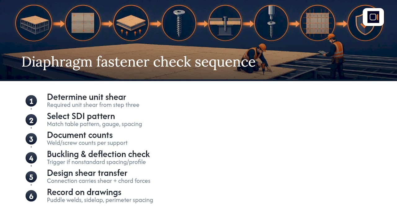
Steel deck diaphragm capacity depends on three fastening interfaces working together: the perimeter fasteners connecting deck to supporting members, the sidelap fasteners between adjacent deck sheets, and the puddle welds or screws at each support. The SDI Diaphragm Design Manual tabulates allowable shear values for standard deck profiles as a function of gauge, fastener pattern, and support spacing, and those tables already account for typical sidelap configurations, so matching your actual fastening pattern to the table's stated pattern matters more than the deck gauge alone.
A typical worked check starts with the required unit shear from step three of the workflow above, then selects a fastener pattern from the SDI table that meets or exceeds that value at the deck gauge specified elsewhere in the structural drawings. Weld or screw counts get documented per support, not just as a general spacing note, because permit reviewers and field inspectors both need a countable quantity to verify. The Metal Deck industry design guide walks through a complete example of this selection process alongside the buckling and deflection checks that follow it.
Panel buckling is a real governing limit on steel deck diaphragms, not a formality. Wide, shallow decking spanning long joist bays can buckle locally under shear before it reaches its tabulated capacity, particularly on thinner gauge material. The SDI tables build in allowable shear values that already reflect these buckling limits for standard configurations, but any nonstandard support spacing or deck profile substitution should trigger a fresh buckling check rather than an assumption that the original table still applies.
Detailing the shear transfer from deck into the supporting structure is where steel deck diaphragms most often run into field problems. Options include welding directly to steel joists, using a ledger angle bolted to masonry or concrete walls, or combining a ledger with a continuous channel where the deck can't reach a suitable bearing element directly. Whatever option you choose, the connection needs to carry both the diaphragm shear and any chord or collector force passing through that same joint, and those forces should be additive in your connection design rather than checked independently.
Document the fastener and weld pattern explicitly in your drawings: puddle weld size and spacing at supports, sidelap screw type and spacing between panels, and perimeter fastener spacing at the diaphragm boundary. A plan reviewer working from the SDI manual will cross-check your stated pattern against the tabulated shear value you claimed, so any mismatch between the drawing note and the calculation sheet is one of the fastest ways to trigger a review comment.
Wood Diaphragm Design: Sheathing, Nailing, Chords, and Sub-Diaphragms
Wood diaphragm capacity comes almost entirely from the sheathing-to-framing nailing pattern, which is why SDPWS Table 4.2A organizes allowable unit shear values by panel grade, minimum nominal panel thickness, nail size, nail spacing at diaphragm boundaries, and framing member minimum specific gravity. Reading that table correctly means matching all four variables to what's actually specified on your drawings, not just picking the closest nail size and assuming the rest lines up.
Boundary nailing, meaning the nail spacing along the diaphragm's continuous perimeter and at panel edges parallel to the load, typically governs the tabulated shear value, while field nailing (into intermediate framing members away from panel edges) is usually a fixed, lighter pattern regardless of the required shear capacity. When your required shear exceeds what standard boundary nailing achieves, your options are tightening the boundary nail spacing, moving to a larger nail size, thickening the panel, or in higher demand cases specifying blocked diaphragms with nailing along all four panel edges rather than just two.
Chord sizing in wood diaphragms almost always runs through the continuous top plate or a dedicated ledger member at the diaphragm boundary. Compute the chord force with T = M / d as described in the workflow section, then check that force against the tension capacity of the top plate splice connection, since the wood member itself rarely governs; the nailed or bolted splice does. Ledger connections at masonry or concrete walls need a separate cross-grain bending and withdrawal check per the applicable wood design standard, since ledgers loaded perpendicular to grain fail differently than a continuous wood chord.
Sub-diaphragms come into play specifically at masonry and concrete wall anchorage, where the primary diaphragm can't directly deliver out-of-plane wall anchorage forces to the main lateral system without an intermediate framing element. A sub-diaphragm is a smaller diaphragm, defined by its own aspect ratio limit, that spans between cross ties or subpurlins to collect the wall anchorage force and deliver it into the main diaphragm or directly into a shear wall. Detailing typically includes continuous cross ties across the full building width, positive connections at each end, and a documented aspect ratio check on the sub-diaphragm itself, since these tend to have tighter aspect ratio limits than the main diaphragm around them.
Handling Openings and Irregular Roof Geometry
Roof openings for skylights, mechanical curbs, or stairwells do more than remove diaphragm area. They concentrate shear at the opening's corners and edges, and that local concentration frequently controls the fastener or weld requirement in that zone even when the diaphragm passes its global shear check everywhere else.
The standard approach is a free-body analysis of the diaphragm segments immediately adjacent to the opening. Isolate the diaphragm area above, below, and to each side of the opening, then trace how the shear that would have passed through the opening redistributes into the remaining panel area around it. That redistribution typically increases the unit shear demand at the opening's perimeter well above the diaphragm's average value, which means the fastener pattern or weld count in that localized zone needs to increase to match, not just extend the average pattern across the whole roof.
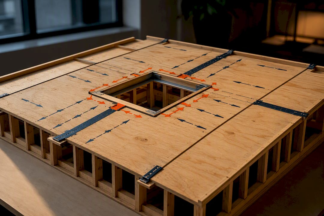
Transfer straps, doubled framing members, or reinforced chord elements around the opening perimeter carry that concentrated force into the adjacent diaphragm area. The strap tie design guide covers strap sizing and connection detailing in more depth, which applies directly here since opening perimeters are one of the most common places straps show up on a set of drawings. Transfer length matters too: the strap or reinforced framing needs enough length past the opening corner to actually develop the force it's picking up, not just enough to look connected on the drawing.
Re-entrant corners, meaning the inside corners created by an L-shaped or irregular roof plan, get similar treatment. Industry guidance commonly recommends increasing connection capacity by roughly 25% at re-entrant corners to account for the stress concentration that occurs there, above and beyond whatever the global shear calculation indicates. Flag these locations early in your design process, because they often end up needing a heavier fastener pattern, a thicker panel, or added blocking that's easier to accommodate before the framing plan is finalized than after.
A Worked Example: Diaphragm Shear, Chord Force, and Fastener Selection
Here's a compact numeric example that walks the full workflow on a simple rectangular wood roof diaphragm.
Assumptions. A single-story rectangular building, 40 feet wide by 60 feet long, with the lateral load applied along the 60-foot direction. Total lateral seismic force tributary to the roof diaphragm is 12,000 pounds, distributed uniformly. Shear walls sit at each 40-foot end, spanning the full 40-foot depth. Roof sheathing is 15/32-inch structural panel, unblocked, over Douglas fir framing.
-
Aspect ratio check. Diaphragm span (60 feet) divided by depth (40 feet) gives an aspect ratio of 1.5, well within typical wood diaphragm limits, so no special aspect ratio penalty applies.
-
Average unit shear. Treating the diaphragm as a simple beam under uniform load, the total shear at each support is half the total load, or 6,000 pounds. Divide by the 40-foot depth:
S = 6,000 / 40 = 150 pounds per linear foot. -
Maximum unit shear. For a uniformly loaded simple-span diaphragm, the unit shear is roughly constant near the supports at that 150 plf value, so this becomes the design shear demand for boundary nailing at the diaphragm edges near the shear walls.
-
Select sheathing and nailing. Checking SDPWS Table 4.2A for 15/32-inch panels with 10d common nails at 6 inches on boundary edges and 12 inches at other panel edges over framing with adequate specific gravity, the tabulated allowable unblocked diaphragm shear comfortably exceeds 150 plf under standard load duration factors, confirming the sheathing choice works without needing a blocked diaphragm.
-
Chord moment and chord force. Maximum moment for a uniformly loaded simple beam is
M = wL² / 8, where w is the load per foot of span (12,000 lb / 60 ft = 200 plf) and L is the 60-foot span:M = 200 × 60² / 8 = 90,000 foot-pounds. Chord force isT = M / d = 90,000 / 40 = 2,250 pounds. -
Check chord capacity. That 2,250 pound tension force needs to be carried across the top plate splice at each panel joint along the chord line. A standard nailed or strap-reinforced splice sized for that force, checked against the applicable wood connection design values, typically closes this out without requiring anything beyond a reinforced plate splice or a light strap.
-
Buckling and constructability check. At this scale and aspect ratio, wood panel buckling isn't a governing concern the way it can be for steel deck, but confirming adequate blocking or edge support at panel joints is still worth a line item in the calculation notes.
-
Summary. The diaphragm works as an unblocked, flexible wood diaphragm with 15/32-inch sheathing, 10d nails at 6 inches on boundaries, a chord force of 2,250 pounds at each long side, and no aspect ratio or buckling concerns. That's the complete set of numbers a plan reviewer needs to see, tied back to the specific SDPWS table used.
Common Pitfalls and a Pre-Submittal QA Checklist
Most diaphragm design comments from plan reviewers trace back to a handful of repeat issues rather than genuine calculation errors. Run through this list before a package goes out:
- Confirm the flexible, rigid, or semirigid assumption is stated explicitly in the calculation notes, not just implied by the analysis method used.
- Verify fastener or weld counts on the drawings match the pattern assumed in the calculation sheet, not a rounded-down field simplification.
- Check transfer length at every strap, collector, and reinforced chord location, since an undersized transfer length is one of the most common items reviewers flag.
- Confirm re-entrant corners and openings received the local shear check and any recommended connection amplification, not just the global diaphragm shear check.
- Run a constructability pass: does the specified nailing pattern or weld spacing actually fit the framing member width without splitting or overlap conflicts?
Pro Tip: Build a standard calculation template with your governing SDPWS or SDI table references pre-loaded for your typical panel and deck types. Reviewers move faster on packages that consistently cite the same table format project to project, and you cut your own risk of transcribing the wrong shear value from memory.
Document every assumption in writing, including the code edition, the specific table number, and the load combination governing the design. A calculation sheet that a reviewer can follow without a phone call back to your office is the fastest one through plan check.
How Practitioners Speed Up Diaphragm Documentation
A complete roof diaphragm calculation package needs consistent inputs across every wall line and roof zone: the same load combinations, the same table references, the same units, carried through from the shear calculation to the final PDF. Doing that by hand across a multi-wing roof with several openings is where transcription errors creep in, usually in the fastener schedule or the chord force summary.
Specialized software platforms organize calculations for 1-story and 2-story wood-framed projects, tracking wall lines, openings, full-height shear segments, hold-down forces, transfer straps, and roof information alongside story drift checks, then exporting the result as a clean PDF report for review coordination. It doesn't replace your engineering judgment on which diaphragm classification applies or how to detail a re-entrant corner, but it keeps the inputs and outputs consistent across a project so nothing falls out of sync between your shear calc and your final drawings. The tutorial library walks through how the reporting workflow fits into a typical submittal package.
Why Most Diaphragm Design Guidance Undersells the Modeling Decision
The conventional advice on roof diaphragm design spends most of its energy on tabulated shear values and nailing patterns, treating the flexible-versus-rigid decision as a formality you check once and move past. That gets the emphasis backwards. The classification decision is where the real engineering judgment lives, because it determines the force each wall line actually sees, and a diaphragm misclassified as flexible when it's really semirigid can send meaningfully more load to a stiff wall line than the tributary-area method predicts.
What gets underrated is documentation discipline. Engineers who are technically capable of the calculation still lose review cycles because the assumptions never made it onto paper in a form a reviewer can verify quickly. A reviewer who has to reconstruct your diaphragm classification from context clues in a set of drawings is going to ask for clarification, and that costs more time than writing one clear sentence would have.
If there's one thing worth prioritizing first, it's running the deflection check against story drift before finalizing the classification, not after. That single comparison tells you whether your simpler tributary-area assumption actually holds up.
— Evalin
Try ShearWise Pro for Your Next Roof Diaphragm Package
Hand-building a fastener schedule, chord detail, and hold-down summary for every wall line on a two-story wood-framed project eats hours you'd rather spend on the engineering itself. ShearWise Pro is built specifically for that gap: it organizes your wall lines, openings, full-height segments, roof information, and story drift checks into one consistent input set, then produces a clean PDF report ready for permit and review coordination.

If you're designing shear walls and roof diaphragms for 1-story or 2-story wood-framed buildings, the platform's shear wall calculator keeps your hold-down forces, transfer straps, and diaphragm inputs tied together instead of scattered across separate spreadsheets. Free trials may include a limited number of watermarked reports, enough to run sample projects through the workflow before committing to a subscription. Sign up to try ShearWise Pro and see how a completed calculation package comes together on your next roof diaphragm design.
Primary Standards to Cite in Your Calculation Package
- ASCE 7 sets the diaphragm classification criteria, force distribution rules, and connection amplification guidance for re-entrant corners and irregularities.
- ANSI/AWC SDPWS provides the nominal unit shear tables for wood structural panel diaphragms by panel grade, thickness, nailing, and framing specific gravity.
- SDI Diaphragm Design Manual tabulates allowable shear values and fastening patterns for steel roof deck, with worked examples for typical profiles.
- APA's engineered wood diaphragm handout distills the SDPWS tables into the practical step-by-step wood diaphragm design sequence.
- Metal Deck industry design guide offers a complete worked steel deck example covering fastening, buckling, and deflection checks together.
Always cite the specific section, table, or edition you used rather than a generic reference to the standard as a whole.
Sources
- Steel deck diaphragm design 101 — Structure Magazine
- Diaphragm Design Manual — Steel Deck Institute (DDM03)
- Roof structure design guide — Metal Deck industry guide
FAQ
What is a roof diaphragm?
A roof diaphragm is the roof sheathing or deck, together with its framing and fasteners, acting as a horizontal structural element that collects lateral wind or seismic forces and delivers them to the shear walls or braced frames below.
What are the three types of diaphragm?
Diaphragms are classified as flexible, rigid, or semirigid, based on how the diaphragm's in-plane stiffness compares to the stiffness of the vertical elements supporting it, a distinction defined in ASCE 7.
Is there a code for diaphragm wall design?
Yes. Roof and floor diaphragm design in the United States is governed primarily by ASCE 7 for load distribution and classification, the ANSI/AWC SDPWS for wood diaphragms, and the SDI Diaphragm Design Manual for steel deck diaphragms.
What is the typical construction method for a wood roof diaphragm?
Wood roof diaphragms are built by fastening structural wood panel sheathing directly to roof framing with a specified nail size and spacing pattern, with boundary nailing at diaphragm edges typically tighter than field nailing across the panel interior.
How does ShearWise Pro fit into roof diaphragm design?
ShearWise Pro organizes the roof and wall line inputs, hold-down forces, and transfer strap information behind a diaphragm calculation and exports the result as a PDF report, though the engineering judgment on classification and detailing remains the designer's responsibility.