
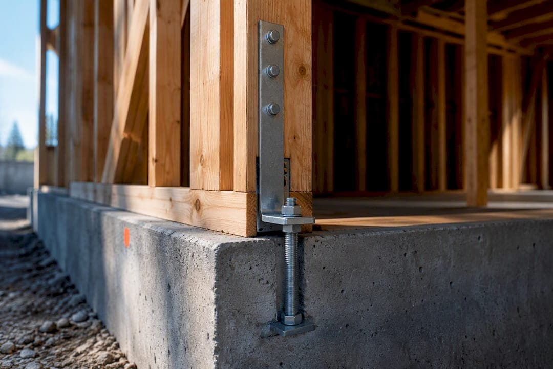
A shear wall holdown is a steel connector that anchors a wall end-post to the foundation or story below, resisting the uplift and overturning forces a lateral load generates. Use conventional stamped holdowns until your calculated factored tension demand exceeds their rated capacity, then move to a continuous rod tiedown system. Check SDPWS Section 4.3, the applicable IBC or IRC provisions, and the manufacturer's ICC-ES ESR before finalizing your connection.
TL;DR:
- Conventional holdowns are suitable for most single- and two-story residential shear walls but may need replacement with continuous rod systems once tension demands exceed their rated capacity.
- Proper installation requires verifying anchor bolt placement, embedment depth, edge distance, and the use of washers as specified by the manufacturer’s ESR, with careful attention to field conditions.
- In multistory or high-seismic buildings, stacked tension demands can significantly increase, often necessitating the use of rod systems with shrinkage compensation devices for proper performance.
- Holdown design must follow specific code provisions and manufacturer evaluations, with extra caution in seismic categories D through F due to cyclic load considerations.
- Using specialized software like ShearWise Pro can streamline calculations, organization, and reporting to ensure compliance and efficiency during design and review processes.
Table of Contents
- What Shear Wall Holdowns Do and Why They Matter
- Codes and Standards That Govern Holdown Design
- Holdown Types and How to Choose One
- Calculating Required Hold-Down Capacity
- Installing Shear Wall Holdowns Without Rework
- Anchorage to Concrete: What the EOR Should Specify
- Inspection and Deformation Limits You Need to Track
- A Practical Checklist for Choosing Your Holdown Approach
- Organize Your Holdown Calculations With ShearWise Pro
- Sources
- FAQ
What Shear Wall Holdowns Do and Why They Matter
Every shear wall works as a cantilevered beam turned on its side. Lateral load, whether wind or seismic, tries to rotate the wall about its base, lifting one end-post while compressing the other. The holdown resists that lift, transferring tension from the end-post into the foundation or into the story below it, and forms a link in the continuous load path required by good structural design.
Connection points matter as much as the device itself. A holdown typically bolts through the end-post, then anchors into a concrete foundation, a steel strap embedded in a slab, or the top plate of the story below in a stacked-wall condition. Fastener arrangements vary by device, but the bolt pattern into the wood member and the anchor into concrete both need independent verification.
Engineered shear walls differ meaningfully from prescriptive braced wall panels in this regard. Prescriptive bracing methods under the IRC often skip explicit holdown calculations, relying instead on standardized panel lengths and spacing. Once you calculate actual demand and specify an engineered shear wall, holdown design becomes mandatory, not optional.
Codes and Standards That Govern Holdown Design
Holdown design draws from several overlapping documents, and knowing which one controls at each stage saves rework. The IBC and IRC set the baseline structural requirements and trigger when engineered design is required versus prescriptive bracing. The American Wood Council's Special Design Provisions for Wind and Seismic (SDPWS) supplies the actual calculation method, including the overturning equation used to size the connector.
Seismic Design Category changes the math. In Categories D, E, or F, hold-down connectors must use approved cyclic load values, or 75% of allowable seismic load values that ignore cyclic effects, whichever the manufacturer's testing supports. That distinction alone can shift a connector selection up a size class.
Manufacturer ESRs then take precedence for installation specifics. An ESR for a given holdown model, like ESR-2330, carries allowable strength and displacement tables that govern over generic code language whenever the two conflict. Two field details worth memorizing: connector bolts into wood framing require steel plate washers, and the standard tensioning guidance is finger-tight plus a half turn before the connection gets covered.

Holdown Types and How to Choose One
Device selection comes down to demand, story count, and how much schedule flexibility you have on site. Here's how the main families stack up.
- Traditional stamped connectors (HDU/HDUE style): cover most single-story and many two-story residential conditions, with allowable tension capacities varying widely depending on model and wood species. They install quickly and inspect easily.
- Post-installed holdowns: offer real adjustability when framing is already up or when a bolt hole comes out of tolerance. They're a common retrofit choice and pair well with epoxy anchors when the original embedment location was missed.
- Continuous rod (ATS) systems: become necessary once factored tension demand exceeds the practical capacity of conventional connectors, which happens routinely in multistory or high-seismic buildings. Rod systems stack tension continuously from roof to foundation through take-up devices at each level.
Constructability considerations follow the device choice. Rod systems need shrinkage compensation devices at each floor to account for wood member settlement over time, and every take-up device adds a deflection component you must track separately from wall panel deflection.
Calculating Required Hold-Down Capacity
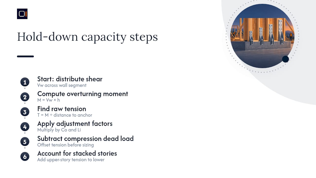
The SDPWS Eqn. 4.3-8 method starts with story shear, Vw, distributed across the shear wall segment. Multiply that shear by the wall height, h, to get the overturning moment, then divide by the distance between the end-post and the resisting anchor to get required tension, T. Two adjustment factors modify the raw number: Co accounts for overturning restraint from other elements, and Li adjusts for the length of the full-height segment resisting the load.
Dead load on the compression side offsets some of that overturning tension, and you subtract it before sizing the holdown, never after. In stacked multistory walls, tension from the upper story adds to the lower story's demand at the same vertical line, which is where undersized conventional holdowns most often get discovered during plan review.
Here's a simplified worked comparison showing how demand can push you from one device family to another:
Pro Tip: Run the calculation for every stacked wall line separately. A holdown that works fine at the roof level often fails once you add the accumulated tension from the story below it.
Installing Shear Wall Holdowns Without Rework
Most holdown failures trace back to a handful of avoidable field mistakes, and catching them before drywall goes up is far cheaper than a retrofit.
- Anchor bolts placed outside the manufacturer's tolerance window are the single most common problem crews report.
- Post-installed anchors and epoxy anchors give you a legitimate remedy when a bolt lands in the wrong spot rather than forcing a re-pour.
- Plate washers on connector bolts into wood framing need to match the size the ESR specifies, not whatever washer happens to be in the truck.
- Bolts should be finger-tight plus a half turn, per code guidance, and no tighter before the wall gets covered.
- Missing embedment depth and inadequate edge distance are the two anchorage errors inspectors flag most often on residential jobs.
Anchor bolt layout deserves its own dedicated review pass on the plan set, not a note buried in a general specification. Our anchor bolt layout guide walks through spacing and embedment detailing that inspectors expect to see called out explicitly.
Anchorage to Concrete: What the EOR Should Specify
The engineer of record needs to put anchor diameter, embedment depth, minimum concrete strength, reinforcement details, and edge distance directly on the plans, not leave them to a deferred submittal. Anchor design affects slab thickness and stem wall reinforcement in ways that ripple into the foundation plan, so it has to happen early, not after framing starts.
ACI anchorage provisions and IBC Chapter 19 both apply here, and manufacturer white papers on rod systems recommend the EOR specify rod diameter, material grade, bearing plates, and shrinkage devices rather than defer them to a supplier. Coordinating masonry and grout detailing around these anchors follows similar embedment and takeoff logic to the CMU layout practices estimators use on concrete block projects. Deferring anchor design to a manufacturer's rep works fine on simple jobs, but on multistory or high-demand walls it invites conflicts discovered too late in the permitting process.
Inspection and Deformation Limits You Need to Track
Special inspection under the IBC typically applies to embedment depth, fastener type, and rod tensioning on any engineered holdown installation. Rod systems carry an added constraint: a common design guideline caps per-story rod deformation at roughly 0.20 inches, and take-up device seating has to be verified separately from calculated deflection under load.
Document these items before final sign-off:
- As-built anchor embedment lengths at each connection.
- Rod tension settings recorded at the time of installation.
- Shrinkage or take-up device settings at each floor level.
- Special inspection stamps and reports tied to the permit submittal.
A Practical Checklist for Choosing Your Holdown Approach
Identify the Seismic Design Category first, since it changes your allowable load basis before you calculate anything. Compute Vw and required tension T, compare that number against your candidate connector's rated capacity, then check for stacked-wall accumulation and shrinkage effects across stories. If demand exceeds conventional capacity or shrinkage stacking gets complicated, specify a rod system and put full anchor details on the plans rather than deferring them. When numbers sit close to a device's rated limit, get supplier engineering support before you commit to the connection.
— Evalin
Organize Your Holdown Calculations With ShearWise Pro
Running holdown calculations by hand across multiple wall lines and stacked stories eats time you'd rather spend on the parts of a project that actually need engineering judgment. ShearWise Pro handles the repetitive math, calculating hold-down forces, transfer strap requirements, and story drift checks for 1-story and 2-story wood-framed buildings, then organizes everything into a reviewer-friendly PDF report.

Engineers, architects, drafters, and designers use it to keep wall lines, openings, and full-height segments organized in one place instead of scattered across spreadsheets. The Three-Report Trial lets you generate three watermarked reports at no cost before committing to a subscription, and paid access is available as monthly or annual plans once you're ready to submit clean reports for permit review. If you're specifying holdowns on your next residential project, sign up to try ShearWise Pro and see how much faster your report turnaround gets.
Sources
For the calculation method itself, the AWC's SDPWS worked examples and errata are mandatory reading. Code compliance runs through UpCodes' hold-down connector provisions and your device's ICC-ES ESR. For multistory rod system design, the SEAW/WABO white paper covers deformation limits in detail, while manufacturer blog posts on holdown selection offer useful field-level context beyond code minimums.
- Shearwall Holdowns in Multistory Wood Buildings and the Canadian Building Code
- Hold-Down Connectors | UpCodes
- Threaded Rod Holdown Systems in Wood Frame Buildings (SEAW/WABO white paper)
FAQ
Do Shear Walls Need Footings?
Yes, shear walls need a foundation element capable of resisting both the vertical load and the overturning tension the holdown transfers down. The footing or stem wall must be sized and reinforced to handle that anchor tension, which is why the EOR needs to specify anchor design rather than leaving it to a generic foundation detail.
What Is the Purpose of Hold-Downs in Framing?
A hold-down resists uplift and overturning forces at the ends of a shear wall, keeping the wall end-post anchored to the foundation or story below during wind or seismic loading. Without it, a shear wall can rotate at its base and lose its ability to resist lateral load entirely.
What Is an HDU2 Hold-Down?
An HDU2 is a stamped steel holdown connector in a common product family used for light to moderate residential tension demands, with allowable capacities defined in its manufacturer's ICC-ES evaluation report. It bolts through the wall end-post and anchors into concrete or steel embedded in the foundation.
What Is a Hold-Down Anchor?
A hold-down anchor is the fastener, typically a bolt or threaded rod, that connects the holdown connector to the concrete foundation or lower-story framing below it. Its embedment depth, diameter, and edge distance all need to be specified on the structural plans, since they directly control how much tension the connection can safely resist.