
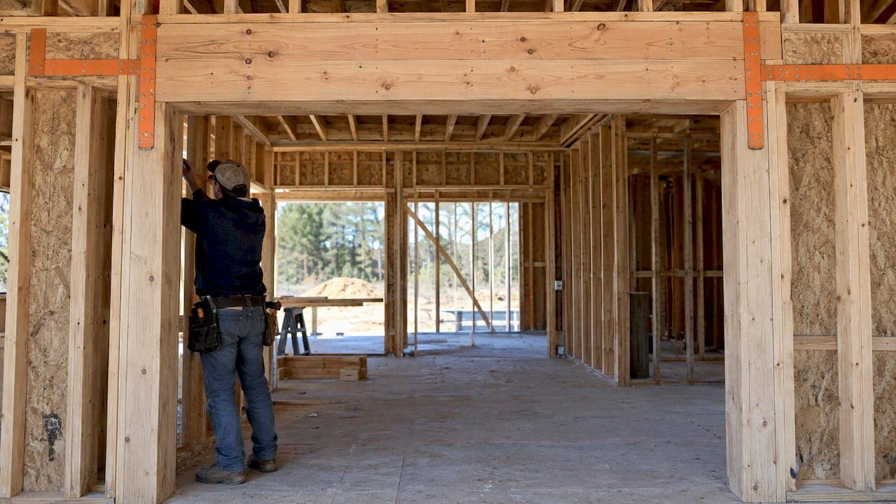
A header can serve as part of a collector only when the member and its connections are explicitly verified for the axial tension and compression forces and the continuity that a diaphragm shear load path demands. Sizing a header for gravity loads alone does not qualify it for collector duty. The two conditions that matter from the outset are a confirmed axial capacity, including reversing seismic cycles, and an unbroken load path into the shear walls or diaphragm boundary elements on either side.
TL;DR:
- Headers used as collectors must be verified for axial tension and compression capacity, especially at openings disrupting shear wall lines.
- The load path must be continuous across openings with detailed straps, blocking, or engineered splices to prevent failure.
- Buckling concerns require lateral stability analysis if a dropped header exceeds prescriptive unbraced length limits.
- Connection and strap details must be documented on framing elevations and included in permit drawings to ensure proper field installation.
- ShearWise Pro automates these calculations, generating review-ready reports for full header and collector verification.
Table of Contents
- When is a header legitimately part of the collector system?
- Design checks and calculation steps to verify a header for collector axial demands
- Detailing and connection options to create collector continuity across openings
- Common pitfalls, verification workflow, and a permit-ready checklist
- Field coordination and detailing tradeoffs worth knowing
- How ShearWise Pro supports header-as-collector verification
- FAQ
- Sources
When is a header legitimately part of the collector system?
A header and a collector solve different problems. A header carries gravity load across an opening in bending. A collector, sometimes called a drag strut, gathers diaphragm shear along a wall line and drags it into shear walls or boundary elements. A member can do both jobs, but only if someone checks the second one separately.
Openings are where collector systems fail. When a wall line is interrupted by a door or window, the diaphragm shear on either side of that gap still needs a path into the shear wall. If the header spanning that opening is not detailed to carry axial force, the load path stops at the opening instead of continuing through it, and WoodWorks guidance on shear wall discontinuity identifies this interruption as the main cause of collector failures in practice.
The load types also differ. Gravity design checks bending and deflection under a steady downward load. Collector design checks axial tension and compression under reversing cycles, since wind and seismic forces push and pull on the same member repeatedly during an event.
Prescriptive code tables cover many gravity header sizes without any engineering input. Collector duty is different: once a header is asked to carry diaphragm shear across an opening, JLC's guidance on lateral-force collectors states plainly that collectors must be continuous and possess both tensile and compressive capacity, which puts the member outside prescriptive tables and into engineered territory.
A few practical triggers tell you when that shift is needed:
- The header spans an opening that interrupts a required shear wall line.
- The lateral analysis shows diaphragm shear accumulating along that wall line.
- The framing plan has no alternate path (truss, blocking, or strap) around the opening.
Design checks and calculation steps to verify a header for collector axial demands
Once a header is flagged for collector duty, the calculation sequence is straightforward even when the numbers get long. Start with the diaphragm shear per foot along the wall line, then accumulate it across the length of the opening the header spans.
- Pull the unit shear (pounds per foot) from your diaphragm or wall line analysis for that level.
- Multiply by the length the header must collect across to get the axial tension or compression demand at each end.
- Compare that demand to the member's allowable axial capacity in tension and in compression, not just its bending capacity.
- Check the splice or connector at each end for tension development, since the connection is often the controlling element rather than the wood itself.
- If the header is dropped below the top plate, run a lateral stability check for the unbraced length before accepting the gravity capacity as-is.
Collected line loads can reach thousands of pounds over a long opening, and plate-splice nailing alone is frequently not enough to carry that force, according to JLC's collector framing guidance, which means supplemental straps or an engineered connector are often necessary rather than optional.
Buckling deserves its own line item. A dropped header loses the lateral support a flush top plate would normally provide, and the WIJMA dropped header design guide recommends a full NDS lateral stability analysis, or added bracing, whenever the unbraced length falls outside the prescriptive bracing diagrams. Skipping this step is one of the more common oversights we see in collector detailing, since the gravity design looked fine in isolation.
Cyclic loading is the last piece. Seismic and wind forces reverse direction, so the connections at each end need to perform in both tension and compression, not just one. That is why strap selection and nailing schedules carry as much weight in the final design as the header size itself. A short reference sketch in your calculation package, showing the accumulated shear arrows feeding into each end connector, keeps this logic traceable for a reviewer later. For a broader view of how these demands distribute across a full wall line, our guide to wood frame building lateral analysis walks through the diaphragm side of the same problem.
Detailing and connection options to create collector continuity across openings
Calculations only matter if the framing detail actually builds the load path. Several connection methods are standard practice for this.
- Straps: placed at each end of the header, extending far enough into solid framing or into the adjacent shear wall to develop the full induced load, per WoodWorks guidance on metal straps around openings.
- Blocking and nailing: a continuous blocking row with the diaphragm sheathing nailed into it ensures the shear actually enters the collector instead of bypassing it.
- Top plate splices: reinforced with sheet-metal straps at the lap when nailing alone cannot develop the required tension, since splice capacity is often the limiting factor in the whole assembly.
- Dropped header bracing: raising the header to flush framing where possible, or adding stiffening blocking and lateral bracing per engineered guidance, avoids the buckling risk discussed above.
Pro Tip: Call out strap length and nailing pattern directly on the framing elevation, not just in a calculation note, so the framer sees the detail at the point of installation.
Drafting notes carry real weight here. Framing elevations should show strap callouts at both ends of the collector header, a nailing schedule for the blocking, and a splice detail wherever the collector crosses a top plate joint. A collector design that lives only in the calculation package and never reaches the framing plan tends to get built as a plain gravity header, which defeats the purpose.

Common pitfalls, verification workflow, and a permit-ready checklist
A few errors show up repeatedly in header-as-collector detailing: treating a gravity header as automatically capable of collector duty, specifying straps without checking their nailing capacity, under-designing the splice connection, and skipping the unbraced-length check on a dropped header entirely. Each one breaks the load path in a different place.
A short verification workflow avoids most of these:
- Confirm the header falls on a wall line carrying diaphragm shear.
- Calculate the accumulated axial demand across the opening.
- Check the member and both end connections against that demand.
- Run the buckling check if the header is dropped.
- Document the strap, nailing, and splice details on the framing plan, not just in the calculation set.
For the permit set itself, reviewers generally want to see the axial calculations, the connection and strap details, nailing schedules at splices, framing elevations showing the full collector path, and a note for field inspection confirming the strap and nailing locations match the drawings.
Field coordination and detailing tradeoffs worth knowing
Oversizing a header to avoid a strap calculation feels efficient on paper, but it rarely solves the real problem, since the connection, not the member, is usually what limits collector capacity. Targeted reinforcement, a strap sized to the actual demand plus a verified splice, tends to cost less and perform more predictably than a larger beam with an unverified connection.
Field coordination matters just as much as the calculation. A strap placed an inch short of solid framing, or a nailing pattern skipped during construction, undoes an otherwise sound design. Getting the framer and the engineer looking at the same detail before the header goes up saves a change order later. A documentation tool that keeps the collector forces, strap details, and PDF output organized in one place removes a layer of back-and-forth during that coordination, which is where we spend a lot of our own attention.
— Evalin
How ShearWise Pro supports header-as-collector verification
We built a tool to organize exactly this kind of calculation for 1- and 2-story wood-framed projects, from wall line layout and openings through hold-down and strap forces to story drift checks.

- The software calculates hold-down and transfer strap forces alongside your shear wall analysis.
- It checks story drift so collector and shear wall demands line up across stories.
- The platform generates clean PDF reports built for reviewer coordination, not raw output.
You can see how these details are documented in a sample ShearWise report, or start with the three-report trial to run your own header and collector calculations before committing to a plan.
FAQ
Can a standard gravity header double as a collector?
Only if it is checked separately for axial tension and compression demand and its end connections are verified for that load, since a gravity header's bending design says nothing about its collector capacity. Without that check, treat the opening as a discontinuity in the load path.
Why do openings cause so many collector problems?
An opening interrupts the wall line, so the diaphragm shear on each side needs an alternate path across the gap, and WoodWorks identifies this interruption as the main source of collector failures. Straps, blocking, or an engineered header are the usual fixes.
What makes a dropped header different from a flush one for collector duty?
A dropped header loses the lateral bracing a flush top plate provides, so its unbraced length can trigger a buckling concern under axial load. The WIJMA dropped header guide recommends an NDS stability check or added bracing whenever the span falls outside prescriptive bracing limits.
Does ShearWise Pro calculate collector and strap forces directly?
Yes, ShearWise Pro calculates hold-down and transfer strap forces as part of its shear wall workflow for 1- and 2-story wood buildings, alongside story drift checks and PDF reporting. Plans start with a three-report trial before moving to a paid subscription.
What should a permit set show for a header acting as a collector?
Reviewers expect the axial calculations, strap and connection details, nailing schedules at splices, and a framing elevation that shows the collector path continuing through the opening. Leaving any one of these out is a common reason for review comments on collector details.
Sources
- Lateral-force collectors for seismic and wind resistant framing — JLC (2003)
- Dropped header design guide (beam stability considerations) — WIJMA