
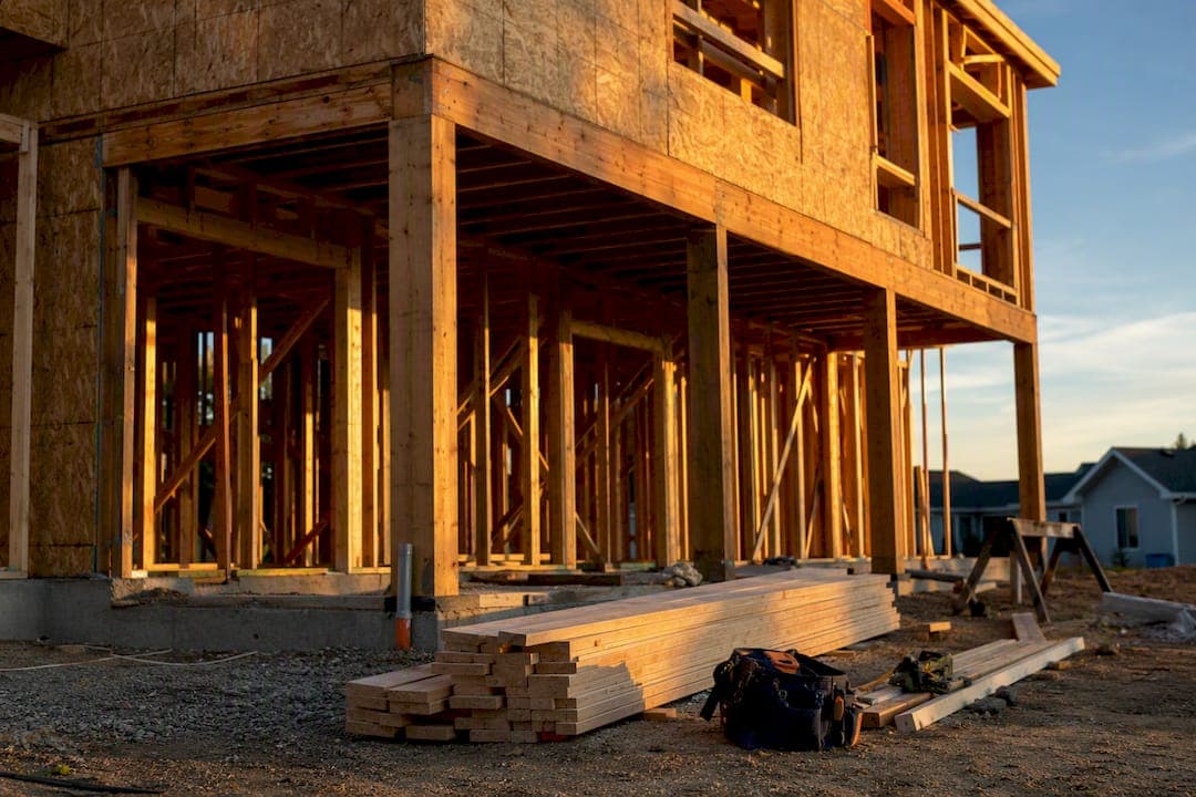
A soft-story condition exists when a story in a 1- or 2-story wood-framed building has less lateral shear-wall resistance than the story above it or than the seismic and wind loads actually demand. In practice, this usually happens at a ground floor with a garage door, a wall of windows, or a wide open-plan layout that leaves too little full-height sheathed wall to resist the story shear.
Once you spot this condition, three things happen to your design workflow:
- You have to trace the load path again, story by story, because the shear demand doesn't stop at the wall line where the opening is.
- Hold-down and anchor forces from the story above add to the story below, so a hold-down sized in isolation is almost always wrong.
- Drift and deflection checks become controlling rather than a formality, especially where aspect ratios push past 2:1.
The rest of this piece walks through the calculations, the detailing, and the report structure a plan reviewer expects to see when a soft-story condition shows up in a 1- or 2-story wood building.
Key Takeaways
A soft-story condition in a 1- or 2-story wood building means one story has insufficient shear-wall capacity relative to demand, and fixing it requires tracing cumulative forces and documenting them clearly enough for permit review.
| Point | Details |
|---|---|
| Definition drives design | A soft story is a story with insufficient lateral shear-wall resistance relative to load, not a general weak-point label. |
| Forces stack, not reset | Hold-down and chord forces from the story above add to the story below wherever walls connect through a diaphragm. |
| Aspect ratio changes capacity | Wall segments beyond a 2:1 height-to-width ratio need the 2w/h shear adjustment before you compare capacity to demand. |
| Non-stacked walls need transfer detailing | Straps, rim joist sizing, and blocking replace hold-downs when walls don't align between stories. |
| ShearWise Pro organizes the report | The platform tracks wall lines, hold-down forces, and drift checks into a clean PDF, with a free trial offering three watermarked reports. |
Table of Contents
- What Creates a Soft-Story Condition in Low-Rise Wood Framing?
- Why a Soft-Story Condition Changes the Calculations You Must Run
- Code-Accepted Methods for Handling a Soft-Story Wall Line
- Key Calculations and Permit Checks Every Report Needs
- Detailing Essentials That Match the Calculations on Paper
- How to Compile a Permit-Ready Shear Wall Report
- What Actually Happens When a Soft Story Fails
- Strengthening Options Beyond Standard Shear Walls
- Building Codes and Retrofit Rules That Apply to Your Project
- What Failure Analysis Teaches About Load Path Continuity
- What the Code Gets Right and Where Engineers Still Get Tripped Up
- ShearWise Pro: Built for This Exact Calculation Chain
- Frequently Asked Questions
- Sources
What Creates a Soft-Story Condition in Low-Rise Wood Framing?
Soft-story conditions in wood-framed residential work almost always trace back to a handful of repeatable plan decisions. Recognizing them early saves you from redoing a shear wall calculation after the framing plan is already locked.
- Garage door openings eat the majority of a front wall line, leaving narrow return walls to carry the entire story shear.
- Large window walls or open-concept living areas reduce the percentage of full-height sheathed wall along a braced wall line, sometimes below what the IRC's braced wall line provisions assume for prescriptive paths.
- Short shear wall segments with height-to-width ratios beyond 2:1 lose allowable unit shear capacity unless you apply the aspect-ratio adjustment.
- Non-stacked walls, where a second-story shear wall doesn't align over a first-story wall, force the load into a transfer condition instead of a clean stack.
Sheathing percentage and opening size drive your Co adjustment factor directly, and low percentages push you toward segmented design or force-transfer detailing rather than a simple full-length wall. If you're unsure whether a wall line qualifies for a prescriptive path, the shear wall ratio for that segment is usually the fastest diagnostic.
Why a Soft-Story Condition Changes the Calculations You Must Run
A soft-story condition doesn't just weaken one wall. It changes which calculations control the entire lateral design for that building line.
Story shear accumulates from the roof diaphragm down. Once you drop a story below a soft condition, the chord and hold-down forces from the level above stack onto that story's own demand rather than resetting to zero. The SE-009 lateral force resistance guidance walks through exactly this stacking effect, and it's the single most common source of undersized hold-downs on two-story wood buildings.
A 2:1 aspect ratio is the line where your allowable shear starts dropping. Past that ratio, and up to 3.5:1, you multiply the allowable shear value by 2w/h per wood shear wall design provisions, and that adjustment often reveals a wall you thought was adequate is actually short on capacity.
Three checks deserve deliberate attention once you've identified a soft story:
- Confirm which diaphragm distribution method you're using (tributary, total shear, or relative stiffness), since unbalanced plans can introduce torsion that a simple tributary split misses.
- Recalculate drift for every narrow segment, not just the longest wall on the line.
- Verify that hold-down demand at the lower story includes the added overturning moment transferred from above.
Code-Accepted Methods for Handling a Soft-Story Wall Line
Three engineered approaches handle a soft-story condition in wood-framed design, and each one trades simplicity for flexibility in a different way.
Perforated shear wall (PSW) treats the entire wall line as one unit and applies a Co adjustment factor based on the percentage of full-height sheathing present. It's the fastest method to calculate, but it requires anchorage at both ends of the wall line and chord forces sized for the full line rather than individual segments. The AWC's perforated shear wall design guidance includes the Co table and two full worked examples for two-story buildings, which is worth reviewing before you commit to this method on a tight footprint.
Segmented shear wall (SSW) treats each full-height section between openings as its own wall, with its own aspect ratio limit and end restraint. This method gives you more design flexibility, particularly on odd-shaped walls, but it multiplies your hold-down count since each full-height segment needs anchorage at both ends.
Force-transfer, or strapping, replaces hold-downs at interior openings with steel straps sized by the Diekmann method, paired with a continuous rim joist or blocking to carry the collector load. This is usually your answer when walls don't stack cleanly between stories.
- PSW: fastest for continuous wall lines with moderate openings.
- SSW: best where segments vary widely in length or restraint condition.
- Force-transfer: necessary for non-stacked walls or where hold-down hardware won't fit architecturally.
Pro Tip: *Don't default to PSW just because it's quicker to run.
Key Calculations and Permit Checks Every Report Needs
A reviewer wants to see the math that proves the load path closes, not just a final pass/fail statement. Here's the sequence that gets you there.
- Compute story shear and unit shear (v) for each wall line, then compare against Vwall using the Co adjustment for openings.
- Calculate tension chord (T) and compression chord (C) at each end of the wall, adding contributions from the story above where the walls stack.
- Run drift and deflection checks, applying the aspect-ratio multiplier for any segment beyond a 2:1 height-to-width ratio.
- Verify collector and diaphragm shear transfer, confirming rim joist and anchor bolt capacity match the calculated demand.
A worked two-story perforated shear wall example typically shows unit shear, uplift anchorage tension, and hold-down sizing all derived from the same Co factor, which is exactly the kind of traceable math the WDF perforated shear wall examples demonstrate step by step. Reviewers move faster when they can follow that same chain in your submittal without cross-referencing three separate sheets.
Detailing Essentials That Match the Calculations on Paper
The calculation only holds up if the drawings show exactly what was assumed. Reviewers flag mismatches between the numbers and the details more often than they flag the numbers themselves.
- Specify hold-down model and anchor bolt embedment at every calculated location, not a generic note referencing "hold-downs per schedule."
- Detail transfer strap attachment length and nailing pattern where straps replace hold-downs, and confirm the anchor bolt layout matches the plate washer size assumed in the calculation.
- Call out whether the rim joist is continuous or requires blocking at the transfer point. Non-stacked walls frequently need both a strap and a specific rim joist detail to close the load path, a pairing that's easy to miss on a quick sketch.
- Show nail schedules for sheathing continuity at panel edges, especially where the Co factor assumed full nailing along the wall line.
Pro Tip: If a hold-down location falls inside a window return or a narrow wall segment less than 24 inches wide, flag it on the plan before the calculation is finalized. That's the single most common RFI on soft-story wall lines, and it's cheaper to catch during design than during framing inspection.
How to Compile a Permit-Ready Shear Wall Report
A permit-ready report earns fewer RFIs when it follows a consistent structure the reviewer can scan in minutes rather than reconstruct from scattered pages.
- One summary page stating the governing loads, whether each wall line passes, and which walls require hold-downs or straps.
- A wall-line table listing segment widths, percent sheathed, and the design method used (PSW, SSW, or force-transfer).
- Per-wall calculation rows condensed to unit shear, chord forces, and drift, with callouts pointing back to the plan and connection details.
- At least one worked numeric example for the most heavily loaded wall, so the reviewer can verify your method rather than just your conclusion.
Reviewers consistently want one summary page that states the conclusion clearly, sufficient capacity or not, required hold-downs or not, and then points directly to the supporting math. A report that buries that conclusion in twelve pages of raw output slows down every review it touches.
ShearWise Pro's sample report and tutorial library show this structure applied to a real two-story wall line, which is a useful reference before you format your own submittal.
What Actually Happens When a Soft Story Fails
The engineering risk in a soft-story condition isn't abstract. It shows up as a specific failure sequence that differs from a typical wall failure elsewhere in the building.
When a soft story lacks adequate shear capacity, the story doesn't just crack sheathing. It can rack laterally in a way that concentrates deformation at that one level while stiffer stories above and below stay relatively intact. That concentration is what makes the condition dangerous: the drift that should distribute across the whole building instead piles up at the weak story, and once nail withdrawal or panel buckling starts, capacity drops fast rather than gradually.
For a 1- or 2-story wood residence, the practical consequences are narrower than a mid-rise soft-story collapse but still serious. Undersized hold-downs let the wall uplift before the sheathing reaches its rated capacity, which means the wall never gets to use the strength you calculated for it. Missing chord continuity at a transfer point can shift load onto a rim joist that was never sized for it, risking a localized failure at that connection rather than a graceful load redistribution.
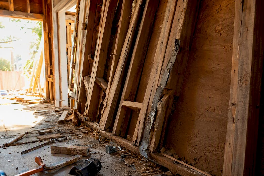
This is exactly why cumulative force tracking and drift checks aren't optional line items. A wall line that "looks fine" on a quick visual scan can still fail the aspect-ratio adjustment or the additive hold-down check, and those are the checks that catch the problem before the framing crew ever sees the plan.
Strengthening Options Beyond Standard Shear Walls
Shear walls handle the vast majority of soft-story conditions in 1- and 2-story wood buildings, but a few projects need something beyond a standard perforated or segmented wall.
Moment frames, typically steel, show up when architectural glazing eliminates enough wall length that no amount of segmented design closes the gap. They're more expensive and require a specialty connection detail, but they let a designer keep an open glass wall while still resisting lateral load at that line.
Base isolation is rare on residential wood construction and tends to appear only on custom high-value homes or structures with unusual seismic exposure. It decouples the building from ground motion using isolators at the foundation, which reduces the force the superstructure ever sees, but the cost and foundation complexity put it outside typical 1- and 2-story budgets.
Wood structural panel overlays and supplemental strapping are the more common middle ground. If field conditions during framing reveal a wall that can't meet calculated demand, adding a plywood overlay or an additional transfer strap is often more practical than redesigning the wall line from scratch.
For most projects in this size range, the right answer is still a correctly calculated and detailed shear wall, not a specialty system. Moment frames and base isolation solve architectural or seismic-exposure problems that shear walls genuinely can't, but they're the exception, not the default, in residential wood-framed practice.
Building Codes and Retrofit Rules That Apply to Your Project
The governing document for shear wall design on 1- and 2-story wood buildings is the IRC, with the IBC applying where a jurisdiction requires engineered design outside the prescriptive path. Both reference the same underlying wood shear wall provisions for allowable unit shear, aspect ratio limits, and connection requirements.
The AWC's Wood Frame Construction Manual supplies the prescriptive tables most residential designers work from first, and it includes worked two-story design examples that mirror the kind of soft-story wall lines this article covers. When a wall line falls outside those prescriptive limits, whether from opening size, aspect ratio, or non-stacked geometry, you move into engineered design governed by the same code but calculated rather than table-selected.
It's worth being clear about scope here: mandatory seismic retrofit ordinances for soft-story buildings, the kind cities enact to require strengthening of existing multi-story structures with weak ground floors, apply to a different category of building entirely and a different design problem. Nothing in those ordinance programs governs how you calculate a shear wall line on a new 1- or 2-story wood residence. Your governing documents are the IRC, IBC where applicable, and AWC's referenced standards, applied at the time of design or permit submission for your jurisdiction.
What Failure Analysis Teaches About Load Path Continuity
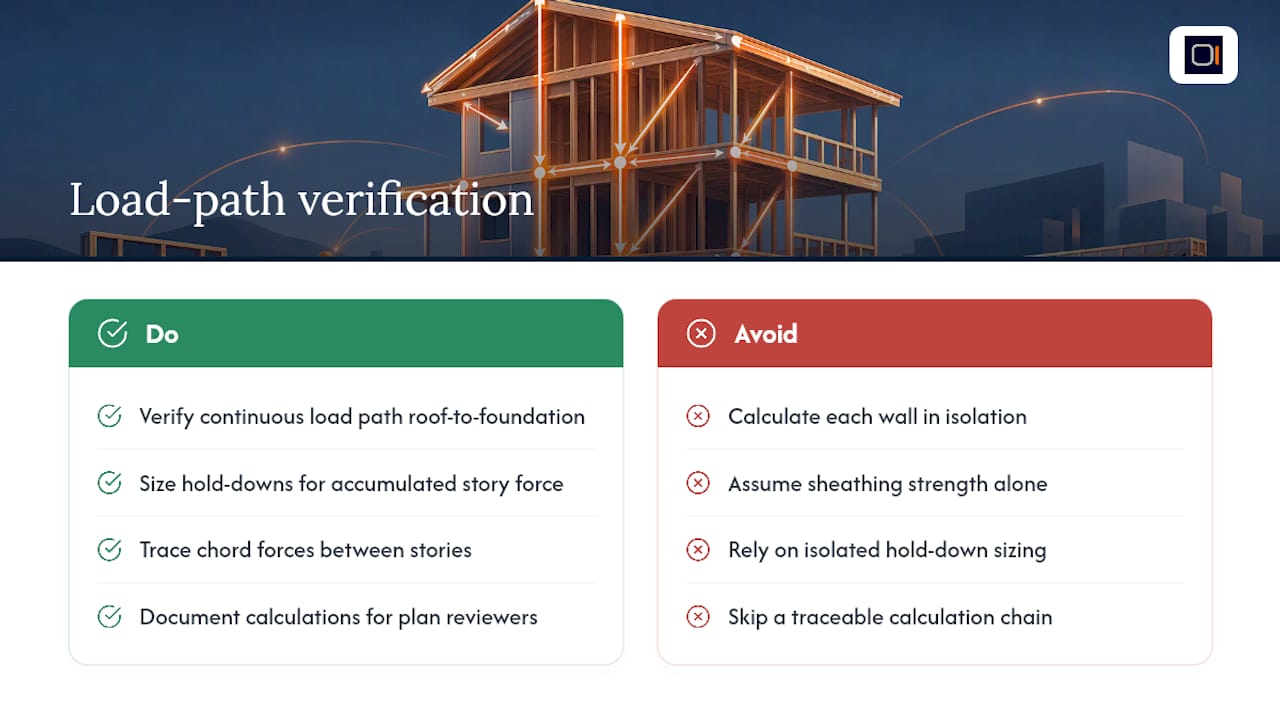
Post-earthquake investigations of light-frame wood buildings consistently point to the same root cause: a broken or undersized load path, not a failure of the sheathing material itself. Walls sheathed correctly but anchored poorly, or hold-downs sized for isolated wall segments rather than the accumulated story force, show up again and again in failure reports as the actual point of collapse.
The PHRC's research on shear wall system behavior makes a point that's easy to underestimate: modern architectural openings have made system behavior more complex than the simple wall-by-wall checks many designers still default to. A building performs as a connected system, and isolated calculations that don't account for how force moves between stories are where mistakes accumulate.
That research finding tracks with what plan reviewers see day to day. The wall lines that generate the most RFIs and the most field corrections aren't the ones with unusual sheathing or exotic hold-down hardware. They're the ones where a designer calculated each wall in isolation and never verified that the chord force from the second story actually made it into the first-story hold-down number.
The practical lesson for 1- and 2-story wood design isn't about avoiding soft-story conditions entirely. Open floor plans and garage door walls aren't going away, and design trends toward open-concept layouts show no sign of reversing. The lesson is that a soft-story condition demands a deliberate, traceable calculation chain from roof to foundation, documented well enough that both you and a plan reviewer can follow it without guessing.
What the Code Gets Right and Where Engineers Still Get Tripped Up
The code itself is not the weak link here. The AWC's perforated and segmented shear wall provisions are well documented, and the aspect-ratio and Co adjustment factors are specific enough that there's little room for interpretation once you've identified the condition correctly. Where things go wrong is earlier, in the step where a designer decides a wall line is "probably fine" without running the cumulative force check that would prove it.
The conventional advice on soft-story conditions tends to focus heavily on identification, spot the garage wall, spot the open floor plan, and stop there. That's necessary but incomplete. Identification without a documented calculation chain is exactly the gap that shows up in post-failure reviews. The real work starts once you've flagged the condition: tracing chord forces down through the stack, applying the right aspect-ratio multiplier, and making sure the hold-down schedule on the drawing matches the number in the calculation.
If there's one priority to take from this, it's that your report should make the load path visible to a stranger. A reviewer who can trace shear, chord force, and hold-down demand from roof to foundation in your submittal will approve faster and ask fewer questions. That's not a documentation nicety. It's the difference between a design that's actually verified and one that just looks finished.
ShearWise Pro: Built for This Exact Calculation Chain
Everything covered above, story shear, Co adjustments, chord forces, hold-down stacking, drift checks, is the exact set of calculations ShearWise Pro organizes into one workflow. Instead of tracking wall lines, openings, and full-height segments across scattered spreadsheets, you enter the geometry once and the platform carries hold-down forces, transfer strap requirements, and story drift checks through to a finished report.

The output is a clean PDF built around the structure reviewers actually want: a summary page, per-wall condensed rows, and hold-down and chord force tables that trace back to your inputs. That's the same structure this article just walked through, minus the hours spent formatting it by hand. You can start with a free trial that includes three watermarked reports before committing to a subscription, which is enough to run a real wall line from your current project and see whether the report format actually cuts down your review comments.
If you want to see the finished product first, look at the sample report or work through the tutorial videos to confirm the workflow matches how you already document a soft-story wall line.
Frequently Asked Questions
What is a soft story building in residential wood framing? It's a story in a 1- or 2-story wood building where the shear wall capacity along one or more wall lines falls short of the lateral demand, usually because openings or open floor plans reduce the sheathed wall percentage.
How do you identify a soft story condition on a plan? Look for wall lines with garage doors, large window walls, or short segments with aspect ratios beyond 2:1. Non-stacked walls between stories are another common trigger that requires a closer look at the calculation.
What's the difference between perforated and segmented shear wall design? Perforated shear wall (PSW) treats the whole wall line as one unit with a Co adjustment for openings, while segmented shear wall (SSW) calculates each full-height section separately with its own aspect ratio and end restraint requirements.
When do you need transfer straps instead of hold-downs? Force-transfer strapping becomes necessary when shear walls don't stack cleanly between stories, since the load has to move horizontally through a diaphragm before it reaches a vertical resisting element.
What should a permit-ready shear wall report include? A summary page with pass/fail conclusions, a wall-line table with segment widths and percent sheathed, per-wall calculation rows, hold-down and chord force tables, and at least one worked example for the most heavily loaded wall.
Sources
- SE-009 Lateral Force Resistance in Residential Buildings
- Design of wood shear walls | UpCodes
- WDF — Perforated shear wall design (AWC)