
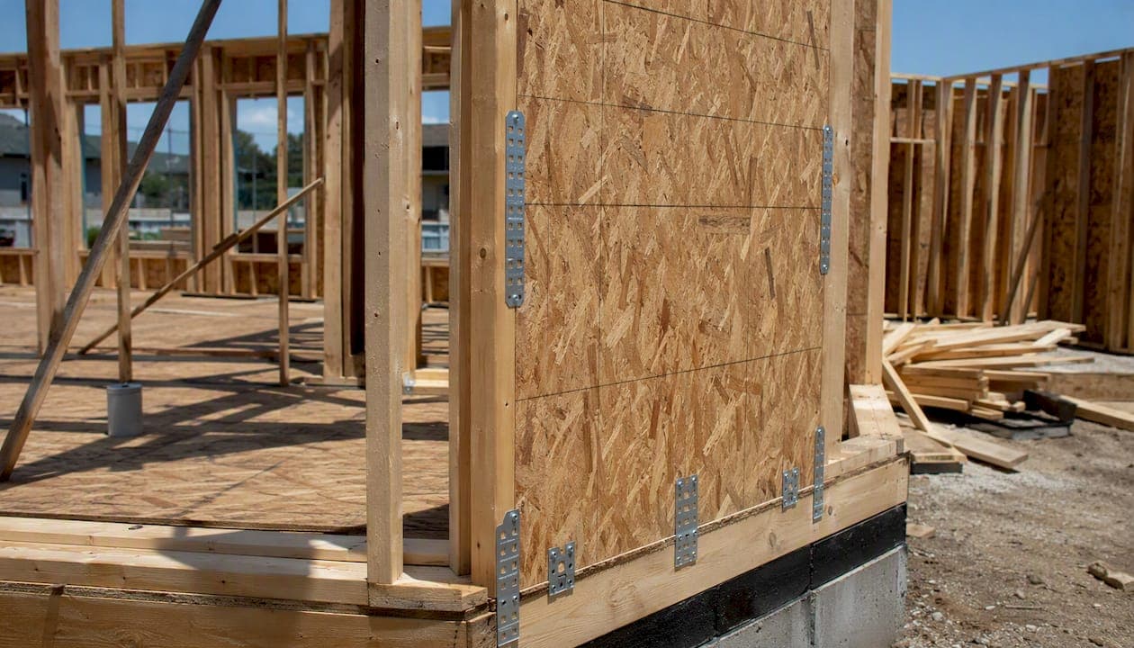
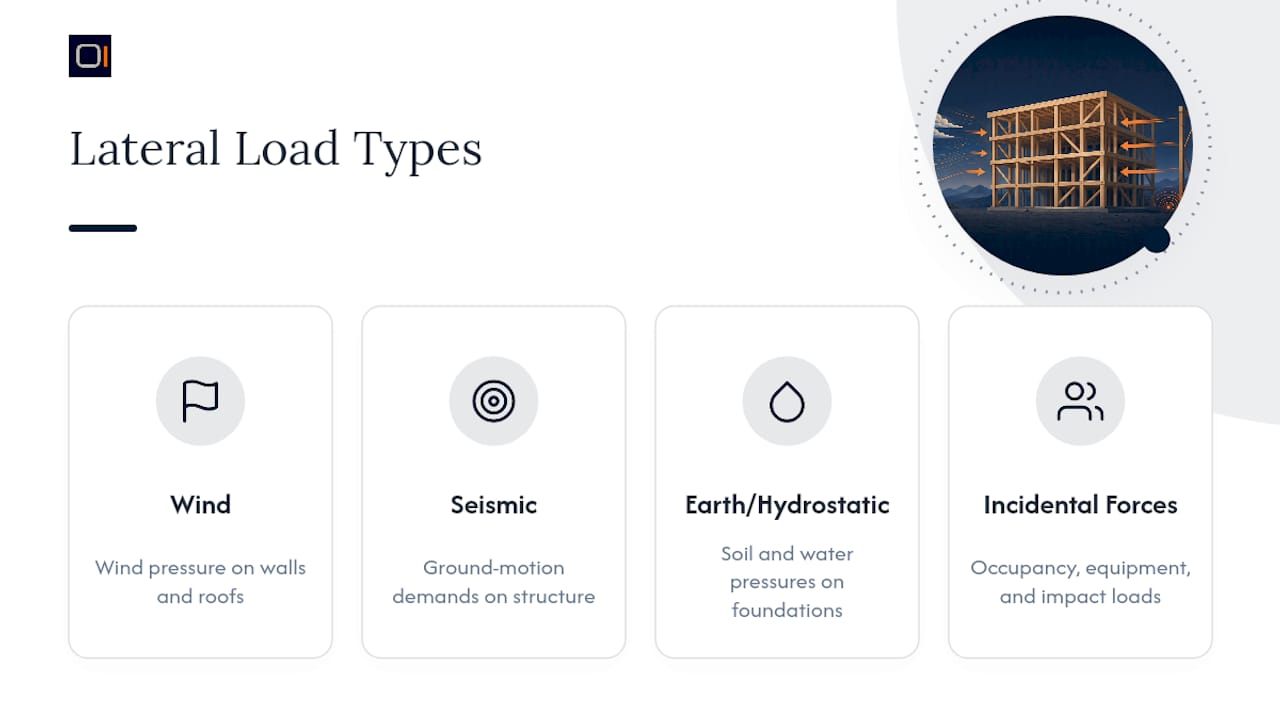
Wood-framed buildings face four primary types of lateral loads: wind, seismic, earth/hydrostatic pressure, and incidental horizontal forces such as impact and guardrail loads. Every one of these acts horizontally on the structure, and U.S. practice requires you to resist them through a continuous lateral-force-resisting system governed by ASCE 7, the International Building Code (IBC), and the AWC Special Design Provisions for Wind and Seismic (SDPWS).
Before you size a single shear wall, confirm these three items:
- Check ASCE 7 and IBC first. Determine your design wind speed, exposure category, seismic site class, and spectral parameters. These inputs control every downstream calculation.
- Verify a continuous load path. Trace lateral forces from the roof diaphragm through collectors and shear walls to the foundation anchors. Any gap in that chain is a code deficiency.
- Confirm sheathing schedule and hold-down capacity. Sheathing type, panel orientation, nail diameter, and nail spacing directly set your shear wall unit shear capacity per AWC SDPWS.
Key Takeaways
Lateral loads in wood structures require a continuous, code-verified load path from the roof diaphragm through shear walls and hold-downs to the foundation, governed by ASCE 7, IBC, and AWC SDPWS.
| Point | Details |
|---|---|
| Four lateral load types | Wind, seismic, earth/hydrostatic, and incidental horizontal forces each require separate code checks under ASCE 7 and IBC. |
| Continuous load path | Every lateral force must trace from the diaphragm through collectors, shear walls, and anchorage to the foundation without a gap. |
| Connections are the weak link | Nail size, spacing, hold-down capacity, and anchor embedment control performance; under-specification is the most common drawing deficiency. |
| Partitions are not primary elements | Research reports partitions contributing 55%–71% of lateral resistance in some studies, but relying on undocumented partitions without jurisdictional approval is a design error. |
| Start load-path checks early | Resolving offsets and collector gaps in schematic design costs far less than redesigning after framing is fixed. |
Table of Contents
- What is a lateral load, and how does it differ from gravity loads?
- Types of lateral loads in wood structures and key design checks
- How lateral loads travel from the roof to the foundation
- Which lateral-resisting systems work best for wood-framed buildings?
- Detailing and connections that control real-world lateral performance
- U.S. code references and required design inputs
- Failure modes and common mistakes to avoid
- Engineering checklist: what to verify on drawings and in the field
- Why lateral checks belong in schematic design, not permit review
- Sources
What is a lateral load, and how does it differ from gravity loads?
A lateral load is any force that acts horizontally on a structure, parallel to the ground plane. Gravity loads (dead load and live load) act vertically downward and are resisted by columns, beams, and bearing walls in direct compression. Lateral loads act perpendicular to that gravity path, inducing shear and overturning in the vertical elements.
ASCE 7 is the primary U.S. standard that defines lateral load categories, load combinations, and the procedures for calculating design forces. The IBC adopts ASCE 7 by reference, and AWC SDPWS provides the wood-specific shear wall and diaphragm design provisions that sit on top of those forces.
Types of lateral loads in wood structures and key design checks
Understanding the full range of lateral loads in wood construction is the starting point for any compliant design. The four categories below cover every horizontal action you are likely to encounter on a 1- or 2-story wood-framed project.
1. Wind loads
Wind pressure acts as a distributed force on the building envelope: positive pressure on the windward face, suction on the leeward face and roof. ASCE 7 Chapter 26–31 defines the procedure. You select a design wind speed from the ASCE 7 wind maps, assign an exposure category (B, C, or D) based on terrain roughness, and apply the appropriate pressure coefficients for the main wind-force-resisting system (MWFRS) and components and cladding (C&C).
Key design checks for wind:
- Confirm design wind speed (V) from ASCE 7 Figure 26.5-1A/B/C for the applicable Risk Category.
- Assign exposure category based on site terrain; Exposure C or D increases design pressures significantly.
- Check roof uplift forces and verify that roof-to-wall connections and wall-to-foundation anchors carry the net uplift.
- Verify diaphragm chord forces and shear wall unit shears against SDPWS tabulated capacities.
- Confirm that cladding attachments meet C&C pressures, which often exceed MWFRS values at corners and edges.
2. Seismic loads
Seismic forces are inertial: the ground accelerates, and the building mass resists that motion. ASCE 7 Chapter 11–12 governs. The design seismic base shear depends on the spectral acceleration parameters (S_DS and S_D1), the seismic site class (A through F), the importance factor (I_e), and the response modification coefficient (R) for the selected lateral system.
Key design checks for seismic:
- Pull site-specific S_DS and S_D1 from ASCE 7 or the USGS Seismic Design Maps tool.
- Assign Seismic Design Category (SDC A through F); SDC D–F triggers additional detailing requirements.
- Distribute story shear to shear walls based on relative stiffness (rigid diaphragm) or tributary width (flexible diaphragm).
- Check story drift against ASCE 7 Table 12.12-1 limits (typically h/100 for light-frame wood).
- Verify that the seismic weight includes all permanent loads plus applicable portions of storage and partition loads per ASCE 7 Section 12.7.2.
3. Soil/earth pressure and hydrostatic loads
Earth pressure acts laterally on below-grade walls, retaining walls, and basement walls. Hydrostatic pressure applies when groundwater is present. Both are treated as sustained lateral loads and must be combined with wind or seismic per ASCE 7 load combinations.
Key design checks:
- Determine active, passive, or at-rest earth pressure based on wall restraint conditions and soil type.
- Verify that basement or retaining wall diaphragm connections can transfer the accumulated earth pressure to the floor diaphragm above.
- Check anchor embedment and foundation reinforcing for combined gravity plus lateral soil pressure.
- Where hydrostatic pressure applies, confirm drainage provisions and design for the full unrelieved head unless drainage is guaranteed by design.
4. Incidental horizontal forces: impact, guardrail, and horizontal live loads
ASCE 7 and IBC specify minimum horizontal live loads for guardrails, handrails, and vehicle barriers. These are typically point or line loads (e.g., 200 lb/ft on guardrails per IBC Section 1607.8) and must be transferred through the floor framing to the lateral system. In podium or mixed-use structures, truck impact loads on parking levels can also govern local framing and collector design.
Key design checks:
- Confirm guardrail and handrail horizontal loads per IBC Table 1607.8.1 and trace the load path to the diaphragm.
- For parking structures or podium levels, check vehicle barrier loads per IBC Section 1607.8.3.
- Verify that local framing members and connections can transfer these concentrated forces without relying on finish materials.
| Load Type | Primary Code Reference | Typical Governing Check |
|---|---|---|
| Wind | ASCE 7 Ch. 26–31 | Diaphragm shear, roof uplift, cladding C&C |
| Seismic | ASCE 7 Ch. 11–12 | Story shear distribution, drift, SDC detailing |
| Earth/hydrostatic | ASCE 7 Ch. 3, IBC | Basement wall anchorage, drainage design |
| Incidental/impact | IBC Section 1607.8 | Guardrail load path, vehicle barrier framing |
How lateral loads travel from the roof to the foundation
The continuous load path is the single most important concept in lateral design. Diaphragms and wood-sheathed shear walls are the primary elements that collect and transfer lateral loads through that path to the foundation. A break anywhere in the chain, whether at a collector splice, a hold-down anchor, or a foundation embed, means the system is incomplete.
The sequence works like this:
- Lateral force enters the diaphragm. Wind or seismic pressure acts on the exterior walls and transfers into the roof or floor diaphragm (plywood or OSB sheathing acting as a deep beam).
- Diaphragm delivers shear to collectors. Chord members carry tension and compression at the diaphragm boundaries; collectors (drag struts) concentrate shear from the diaphragm into the shear wall end zones.
- Shear walls resist in-plane shear and overturning. The sheathed wall panel carries unit shear; hold-downs or continuous rods resist the overturning tension at the wall ends.
- Anchorage transfers forces to the foundation. Anchor bolts, embedded plates, or continuous rod systems carry shear and uplift from the sill plate into the concrete foundation.
Common complications arise with offset shear walls, large floor openings, and staggered wall lines. When a shear wall on the upper story does not stack directly over a shear wall below, a transfer diaphragm or collector must bridge the offset. SDPWS describes segmented, perforated, and force-transfer-around-openings (FTAO) shear wall methods, each with different hold-down force and deflection implications. Practitioners recommend establishing the continuous load path during schematic design; resolving offsets after framing is fixed is expensive and disruptive.
Pro Tip: Sketch a simple load-path diagram early in schematic design, one arrow per story from roof to foundation. If you cannot draw a continuous arrow without a gap, you have a design problem to resolve before detailing begins.
Which lateral-resisting systems work best for wood-framed buildings?
The right system depends on your building geometry, Seismic Design Category, and architectural constraints. For a detailed breakdown of system components, the wood building lateral system components guide covers diaphragms, collectors, and shear walls in depth.
Shear wall systems are the standard choice for light-frame wood construction. They are straightforward to design using SDPWS tabulated values, and their behavior under both wind and seismic loading is well-documented. The main constraint is openings: large windows or garage doors reduce the available full-height shear segments and increase hold-down demands on the remaining segments.
Braced frames (diagonal bracing) offer an alternative where shear walls are architecturally impractical. They are efficient in steel-hybrid or heavy-timber applications but less common in light-frame wood because the diagonal member connections are more complex and the system is less forgiving of shrinkage.
Moment-resisting frames have limited use in conventional light-frame wood. They appear in special cases, such as open-front structures or podium transfers, where a moment frame at the ground level supports a wood-framed structure above. These require careful connection detailing and are typically designed by the structural engineer of record (SEOR) with project-specific calculations.
CLT and large-panel shear walls are gaining traction in mid-rise wood construction. CLT panels act as monolithic shear walls with high in-plane stiffness, but their connection detailing differs significantly from light-frame practice. Hold-down forces concentrate at panel-to-panel and panel-to-foundation joints, and the design must account for rocking and sliding mechanisms. For wood framing lateral systems, the choice between these systems ultimately comes down to load demand, story count, and the architectural program.
Detailing and connections that control real-world lateral performance
Connection details, not member strength, are the most frequent real-world weak link in lateral systems. Research confirms that designers should prioritize connection capacity, sequencing, and shrinkage compensation above almost everything else in the detailing phase.
Sheathing type and fastener layout
Sheathing material, thickness, nail diameter, and nail spacing directly set the unit shear capacity of a shear wall. Structural panels (SP) generally show higher shear-bearing capacity than OSB in monotonic tests, and nail diameter and spacing matter as much as panel grade. Large-scale racking tests confirm that panel orientation and joint configuration materially affect both capacity and stiffness. Vertical sheathing is the standard recommendation; glued horizontal panels can increase capacity when specifically designed and detailed. For a code-focused breakdown of sheathing options, the sheathing in shear walls guide covers nailing schedules and panel properties in detail.
Hold-downs, straps, and continuous rod systems
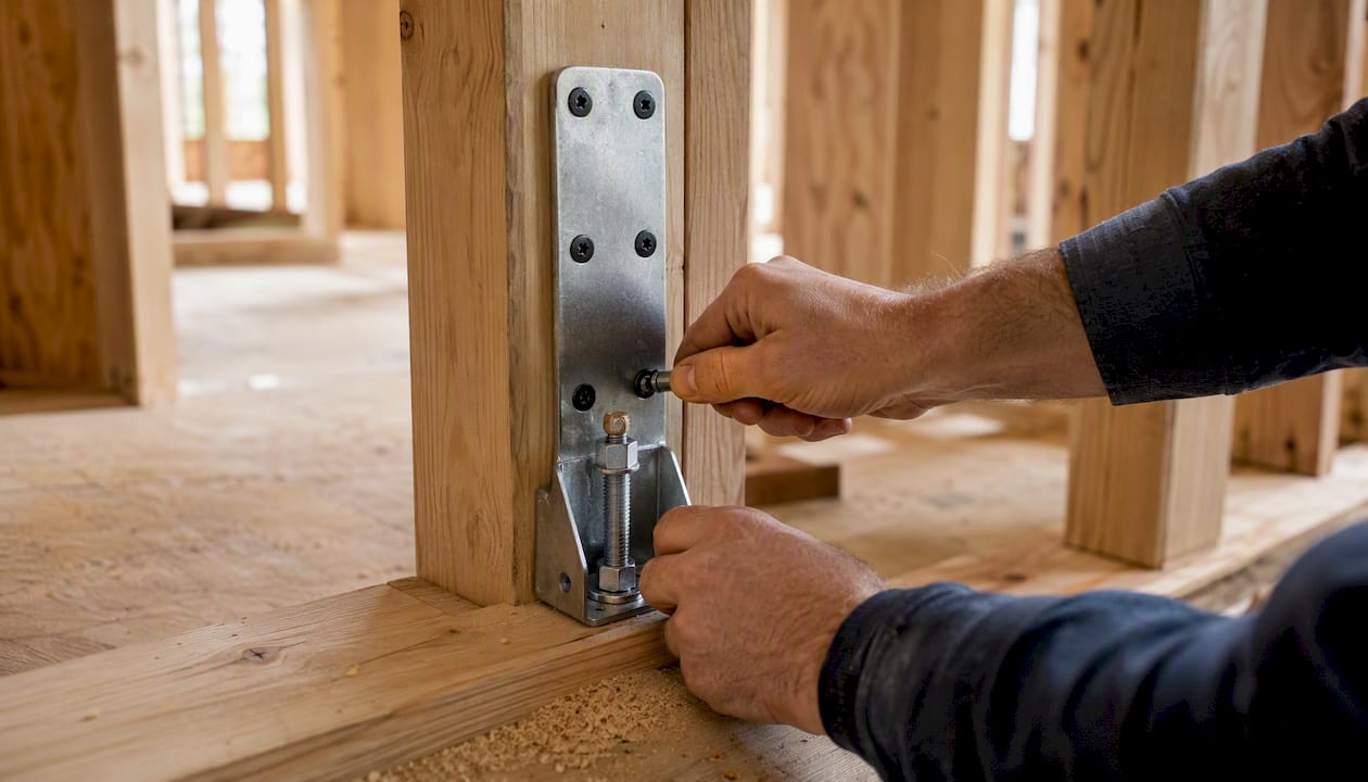
Traditional hold-downs (Simpson Strong-Tie HDU or equivalent) bolt to the end stud and anchor to the foundation or floor framing below. They are straightforward to install and inspect, but each floor level requires a separate device, and wood shrinkage can introduce slack over time.
Continuous rod systems thread a single threaded rod from the foundation through multiple stories, with shrinkage-compensating devices (bearing plates with take-up hardware) at each floor. They remove the need for heavy tension posts at shear wall ends and can transfer overturning forces exceeding 40 kips ultimate in podium or heavy-load cases. The trade-off: they require shop drawings, field labeling, and correct installation sequencing. Always require vendor shop drawings for continuous rod systems and verify that the SEOR has reviewed them. For guidance on hold-down rods in multi-story buildings, the detailing differences between floors are significant.
Strap ties handle shear transfer at horizontal joints, such as top plate to rim joist or rim joist to sill plate. Sequencing matters: straps installed after drywall or after adjacent framing is complete may not achieve their rated capacity.
Anchorage to foundations
Anchor bolts (typically 5/8" diameter per IBC minimum) transfer sill plate shear to the concrete foundation. In high-seismic or high-wind zones, shear capacity often requires plate washers and closer anchor spacing than the IBC minimum. Post-tension slabs, precast foundations, and CMU walls each present different embedment and sequencing constraints. Coordinate anchor locations with the foundation engineer before the slab is poured.
Pro Tip: Specify plate washers on every shear wall anchor bolt, not just where the calculation demands them. The added cost is negligible; the inspection clarity is significant.
Construction document checklist for detailing
- Sheathing schedule: panel grade, thickness, orientation, and blocking requirements for each shear wall and diaphragm zone
- Nailing schedule: nail diameter, length, and spacing at panel edges and field for each unit shear demand
- Hold-down locations, device designations, and design capacities at every shear wall end
- Collector/drag strut member sizes, splice locations, and connection details
- Strap tie locations, orientations, and rated capacities at all horizontal shear transfer joints
- Anchor bolt diameter, spacing, embedment depth, and plate washer requirements at all shear wall sill plates
- Continuous rod system: rod diameter, bearing plate locations, take-up device specifications, and shop drawing requirement note
- Foundation embed schedule coordinated with structural foundation drawings
U.S. code references and required design inputs
Every lateral design for a wood-framed building in the U.S. runs through three governing documents.
ASCE 7 sets the load demands: wind pressure procedures (Chapters 26–31), seismic force procedures (Chapters 11–12), load combinations (Chapter 2), and drift limits (Section 12.12). It is the source for design wind speed, exposure category, seismic site class, spectral parameters, and importance factors.
IBC adopts ASCE 7 by reference and adds prescriptive requirements for wood construction, including minimum anchor bolt spacing, shear wall construction requirements, and the braced wall panel provisions of IBC Section 2308 for conventional construction.
AWC SDPWS provides wood-specific shear wall and diaphragm design. It covers tabulated unit shear capacities, the three shear wall methods (segmented, perforated, FTAO), deflection equations, and boundary element requirements. SDPWS Section 4.3 governs wood-frame shear walls; Section 4.2 governs diaphragms.
Required inputs before sizing any lateral system:
- Design wind speed (V) and exposure category from ASCE 7 wind maps
- Seismic site class and S_DS / S_D1 from USGS Seismic Design Maps or a geotechnical report
- Risk Category and importance factor (I_e) per ASCE 7 Table 1.5-1
- Building weight (seismic mass) including all permanent loads and applicable live loads
- Diaphragm rigidity assumption (flexible vs. rigid) per ASCE 7 Section 12.3
- Design method: LRFD or ASD. SDPWS supports both; LRFD is increasingly common for seismic design because it aligns directly with ASCE 7 strength-level forces. ASD remains widely used for wind design in residential practice.
- Story drift limits: ASCE 7 Table 12.12-1 sets h/100 for light-frame wood structures under seismic; wind drift is a serviceability check, typically h/240 to h/300 by convention.
For a deeper look at lateral load distribution and diaphragm-shear wall interaction, the distribution guide covers flexible versus rigid diaphragm assumptions and their effect on wall line demands.
Failure modes and common mistakes to avoid
Most lateral system failures in wood buildings trace back to a handful of recurring problems. Knowing them in advance is the fastest way to catch them on drawings before they reach the field.
Connection failure is the most common weak link. Undersized nails, wrong nail spacing, missing plate washers, and uninstalled hold-downs all reduce capacity without any visible sign in the framing. Specify fasteners completely on the drawings; do not leave nail size to the contractor's discretion.
Discontinuous load path occurs when a shear wall on one story does not align with a resisting element below, and no collector or transfer diaphragm bridges the gap. This is particularly common in modern residential layouts with open floor plans and large glazing areas.
Reliance on undocumented partitions. Peer-reviewed research indicates that internal partitions can contribute roughly 55%–71% of total lateral resistance in some low-rise wood buildings. That contribution is real, but designers should not rely on undocumented partitions as primary resisting elements without jurisdictional approval and explicit design documentation.
Insufficient anchorage. Anchor bolt spacing that meets the IBC minimum for gravity may be inadequate for the shear demand at a high-unit-shear wall. Always check anchor capacity against the calculated shear demand, not just the prescriptive minimum.
Late-stage framing changes. A window added after the shear wall layout is set can eliminate a full-height segment and break the load path. Establish a change-control process that routes framing modifications through the SEOR before construction.
Under-specified fasteners. Calling out "16d nails at shear walls" without specifying diameter, length, and spacing is a common drawing deficiency.
Engineering checklist: what to verify on drawings and in the field
Run through these items during plan review and again during framing inspection.
- Confirm the design basis. Verify that the design wind speed, exposure category, seismic site class, SDC, and importance factor on the drawings match the project address and the current edition of ASCE 7 and IBC.
- Trace the continuous load path. Follow lateral forces from the roof diaphragm through each floor diaphragm, collectors, shear walls, and anchorage to the foundation. Confirm no gaps or unresolved transfers.
- Check the diaphragm sheathing schedule. Confirm panel grade, thickness, orientation, edge nailing, and blocking requirements are fully specified for each diaphragm zone.
- Locate and size all collectors and drag struts. Verify that collector members are identified, sized for the calculated axial demand, and that splice connections are detailed.
- Confirm shear wall segments. Verify that full-height shear segments are identified, that the unit shear demand is within the SDPWS tabulated capacity for the specified sheathing and nailing, and that the design method (segmented, perforated, or FTAO) is consistent with the detailing shown.
- Check hold-down locations and capacities. Every shear wall end that develops overturning tension needs a hold-down or continuous rod device with a rated capacity equal to or greater than the calculated demand.
- Verify anchor bolt schedule. Confirm diameter, spacing, embedment depth, and plate washer requirements at all shear wall sill plates. Cross-check against the foundation drawings.
- Run story drift checks. Confirm calculated story drift is within ASCE 7 Table 12.12-1 limits. For wind, verify serviceability drift meets the project's adopted limit.
- Review continuous rod shop drawings. If continuous rod systems are specified, confirm that shop drawings have been submitted, reviewed by the SEOR, and that shrinkage-compensating devices are included at each floor.
- Field-verify nailing. During framing inspection, spot-check nail diameter, length, and spacing at shear wall sheathing edges and at diaphragm boundaries. This is where specification errors most often surface.
Why lateral checks belong in schematic design, not permit review
The most expensive lateral design problems are the ones discovered at permit review or, worse, during construction. Offsets, large openings, and podium transfers that look straightforward on an architectural plan can require substantial collector framing and hardware once the load path is traced. Resolving those issues after the structural system is set costs far more in redesign time than catching them in schematic design.
The practical lesson: sketch the load path on day one. Identify where shear walls will stack, where collectors will run, and where hold-downs will land before the architectural layout is frozen. Coordinate foundation anchor locations with the civil and foundation engineer before the slab design is finalized. And use a calculation workflow that keeps sheathing schedules, hold-down forces, and drift checks organized in one place, so nothing falls through the cracks between design phases.
Lateral design software can help you organize these checks systematically, particularly on projects where multiple wall lines, story offsets, and complex hold-down schedules make manual tracking error-prone.
Sources
- Design guide: Introduction to lateral design (X305, 2021)
- Practical considerations for lateral analysis of modern light-frame wood buildings (Landry & Cagle, 03.2026)
- Journal of Structural Engineering (re: contribution of partitions to lateral resistance) — 2021
- Experimental study on wall-panel racking resistance and stiffness (Springer, 2025-09-29)

ShearWise Pro organizes your shear wall calculations, wall line layouts, hold-down forces, transfer straps, and story drift checks in one place, then exports clean PDF reports for permit and review coordination. It is built specifically for 1-story and 2-story wood-framed projects, so the workflow matches the way you actually design. Try ShearWise Pro free with three watermarked reports, no commitment required.