
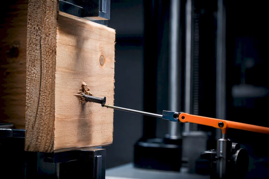
Nail slip at the sheathing-to-framing connection is one of the four terms in the SDPWS shear wall deflection equation, and in many assemblies it is the largest and hardest to quantify. It reduces initial stiffness, changes how a wall dissipates energy under cyclic load, and can shift the governing failure mode away from the sheathing panel and toward the fastener itself. The sections below cover the mechanics, the experimental record, modeling approaches, and the design choices that keep slip from becoming a surprise in your drift or hold-down calculations.
TL;DR:
- Nail slip significantly reduces initial wall stiffness and increasingly influences energy dissipation during cyclic loading, especially after multiple load reversals.
- Fastener head geometry, nail shank type, and wood moisture condition can cause notable variations in load-slip behavior and failure modes, affecting shear capacity estimates.
- Accurate modeling requires implementing load-slip curves as nonlinear connectors, with inputs tailored to nail type, spacing, panel thickness, and moisture, rather than simplifying to a single stiffness value.
- Increasing nail spacing from 6 to 3 inches on center and selecting nails with larger heads or ring shanks can reliably reduce slip and improve shear wall capacity.
- The biggest knowledge gaps remain in understanding how long-term moisture and head geometry influence slip and shear stiffness, emphasizing the need for standardized test data and sharing across labs.
Table of Contents
- Mechanics of nail slip: load-slip behavior and failure modes
- Key experiments and what they show about slip's effect on stiffness and capacity
- How to model nail slip in analysis: connectors, curves, and software practice
- Design choices and detailing to limit adverse effects of nail slip
- Test setups and measurement techniques to quantify slip
- How nail slip alters wall-level outcomes and when it matters
- Practical worked example and tool-assisted workflow
- Where the field still needs better data
- ShearWise Pro as an efficiency aid for slip-aware checks
- Sources
- FAQ
Mechanics of nail slip: load-slip behavior and failure modes
A single nail connecting sheathing to a stud does not behave like a rigid pin. Under lateral load, it develops a load-slip curve: an initial near-linear stiffness region (often called K0), a yield transition, and a post-yield plateau where the nail bends and the wood around it crushes locally. That curve is the fundamental building block of shear wall stiffness, and it is fundamentally nonlinear from the first increment of load.
Under cyclic loading, the picture gets more complicated. Each load reversal traces a slightly different path than the one before it, producing pinched hysteresis loops that narrow as the wood fibers around the nail shank degrade. This path dependency is why a wall's stiffness measured on the first cycle of a test is almost always higher than its stiffness on a later cycle at the same displacement, and it is also why linear elastic assumptions break down quickly once a wall sees more than a few reversals.
Failure at the fastener level tends to fall into a handful of recognizable modes:
- Withdrawal: the nail pulls axially out of the framing member, common with smooth-shank nails under load reversal.
- Pull-through: the nail head punches through the sheathing panel, often governed by head diameter and panel thickness.
- Fatigue: repeated bending cycles crack the nail shank near the shear plane, typically seen only after extended cyclic demand.
- Tear-out: the wood fibers around the nail hole split or crush, reducing the effective bearing area and accelerating slip.
Which of these governs depends heavily on fastener geometry and wood condition. Moisture content changes the crushing resistance of the wood fibers around the shank, so a wall built with green lumber and tested dry (or vice versa) can show a materially different apparent shear stiffness (Ga) than the same assembly at equilibrium moisture. Panel grade matters too: OSB and plywood have different edge fiber characteristics that affect how cleanly a nail head seats and how much local crushing occurs before slip stabilizes. Joint detailing, including nail spacing near panel edges and whether both faces of a wall are sheathed, further shifts how slip redistributes across the wall rather than concentrating at a few fasteners. The 2021 SDPWS errata specifically flags this last point: when nail spacing drops below 6 inches on center on both faces, simply doubling a single-face stiffness assumption tends to misrepresent how the two sheathing layers actually share slip.
Key experiments and what they show about slip's effect on stiffness and capacity
The experimental record on nail slip spans single-fastener lateral tests, full-scale cyclic wall tests, and a growing set of seismic repeat-loading studies. Together they explain why slip shows up so consistently as a governing term in wall deflection rather than a minor correction.
Full-scale cyclic wall testing under protocols like CUREE has repeatedly shown that nail slip accumulates progressively through a loading sequence, and that this accumulation is a primary driver of the widening deformation seen late in a test. A 2024 seismic performance study on light wood shear wall infilled timber frames found that repeat cyclic loading produced progressive nail slip that modified the hysteresis shape of the wall over the course of the test, confirming that slip is not a one-time deflection penalty but an evolving contributor to system response.
Fastener head geometry turns out to matter more than many designers assume. An ASCE study on sheathing nail head geometry tested full-round head (FRH), clipped head (CLP), and casing-head (CSE) nails under comparable conditions.
| Nail head type | Relative nominal shear strength |
|---|---|
| Full-round head (FRH) | Baseline |
| Clipped head (CLP) | Comparable to FRH |
| Casing head (CSE), some configurations | Approximately 78% of FRH |
Some casing-head nails reached only about 78% of full-round-head nominal shear strength in the ASCE test series, a gap large enough to matter in a capacity calculation if the specified fastener is substituted without checking its head geometry.
Nail bending-yield stress (fyb) has a similar nonlinear relationship with performance. Increasing fyb raises peak capacity, but that benefit plateaus around a bending-yield stress in the neighborhood of 145 ksi; beyond that point, additional strength does not meaningfully improve cyclic performance and instead raises the risk of a nonductile failure mode, where the nail snaps rather than bending and dissipating energy. That tradeoff is a reminder that higher fastener strength is not automatically better for seismic performance.
A separate body of work on fabrication method points in a practical direction. A conference paper comparing stapled and nailed wall assemblies found that prefabricated panels showed more consistent nailing and less variability in performance than walls nailed on site, a difference tied directly to how uniformly slip develops across the panel.

How to model nail slip in analysis: connectors, curves, and software practice
Modeling nail slip well starts with resisting the temptation to reduce it to a single stiffness number. The SDPWS gives multi-point load-slip data in Table C4.2.3D, and those points are meant to be used as a curve, not averaged into one linear spring constant. Translating that table into a nonlinear connector definition, whether in a general finite element package or a purpose-built shear wall tool, means feeding in the load and corresponding slip at each tabulated point so the connector traces the same nonlinear path a real nail would under load.
A linearized single-term deflection approximation is convenient, and it is often close enough for a preliminary check. It becomes unacceptable once you are checking drift near a code limit, evaluating hold-down demand in a wall with irregular openings, or modeling a wall expected to see several large cyclic reversals, because linearization systematically underestimates the deflection contributed by slip once the nail moves past its initial stiffness region. Practice guidance built around RFEM-style modeling shows how these nonlinear load-slip curves get implemented as nonlinear line hinges between sheathing and framing elements in a finite element model, which improves the prediction of both stiffness and how load redistributes once individual fasteners start to yield.
Setting up a slip-sensitive model requires a short list of inputs, each chosen deliberately rather than defaulted:
- Nail size and type: diameter, length, and shank pattern (smooth, ring, or screw) set the base load-slip curve.
- Spacing: edge and field spacing determine how many fasteners share the load and how slip distributes.
- Panel type and thickness: OSB versus plywood and panel gauge affect local crushing resistance at the nail.
- Moisture correction: apparent shear stiffness values need adjustment when construction moisture differs meaningfully from equilibrium conditions.
Pro Tip: Before trusting a nonlinear connector curve in a critical design, check it against single-nail lateral test data or a manufacturer's published load-slip curve for that exact fastener, since small differences in shank geometry can shift the curve enough to matter at the wall level.
For a full walk-through of how the four SDPWS deflection terms combine in a real wall, the SDPWS deflection guide works through a worked example alongside the code formula.
Design choices and detailing to limit adverse effects of nail slip
Once you accept that slip is a governing deflection term rather than a rounding error, a few design decisions follow directly. Nailing schedule is the first lever: tightening edge spacing from 6 inches to 4 inches or 3 inches on center increases the number of fasteners sharing the load and reduces the slip demand on any single nail, which is why code-tabulated shear capacities climb as spacing tightens. Fastener selection is the second lever, and it is easy to get wrong: specifying a common nail where the design assumed a ring-shank nail, or substituting a casing-head nail for a full-round-head nail, changes the load-slip curve and the nominal shear capacity in ways that are not always obvious from the diameter alone. Panel thickness is the third lever, since a thicker panel resists local crushing around the nail head better and slows the onset of pull-through.
Head geometry deserves specific attention because it is easy to overlook on a drawing set. Full-round-head and clipped-head nails performed comparably in ASCE testing, but some casing-head nails reached only about 78% of that nominal strength, likely because the smaller head diameter allows earlier pull-through. Shank type follows the same logic: a smooth shank slips more readily under withdrawal-prone loading than a ring-shank or screw-shank fastener, which is why cyclic-critical assemblies often specify ring-shank nails even when a smooth shank would satisfy a static capacity check.
A practical detailing checklist for a typical residential wood shear wall:
- Confirm the specified nail diameter, length, and head type match what the shear capacity table assumes, not just the nominal size.
- Verify edge and field spacing against the governing table, and check that spacing tightens appropriately near panel edges and corners.
- Check panel thickness and grade against the fastener schedule, since thin panels combined with aggressive nailing can shift failure toward pull-through.
- Review moisture exposure at the time of construction and note where a correction to apparent shear stiffness (Ga) may apply.
- Confirm hold-down capacity accounts for the deflection contribution of nail slip rather than assuming a rigid connection at the wall ends.
- Flag any wall with double-face sheathing and close nail spacing for explicit two-face modeling rather than a doubled single-face assumption.
Pro Tip: Where budget and schedule allow, prefabricated wall panels tend to show tighter control over nail placement and driving depth than field-nailed walls, which shows up directly as less variability in measured slip and stiffness.
Common calculation mistakes tied to connector assumptions, including some of the ones above, are covered in more detail in the guide to shear wall design mistakes, and a broader set of nailing schedule examples appears in the nailing schedules guide.
Test setups and measurement techniques to quantify slip
Quantifying nail slip reliably requires two distinct test scales, and researchers generally run both. A single-nail lateral test isolates one fastener between a sheathing coupon and a framing member and loads it monotonically or cyclically while recording the full load-slip curve. The key outputs are the initial stiffness (K0), the load at first yield (Vyield), and the complete curve shape through the post-yield plateau, all of which feed directly into the multi-point connector definitions used in nonlinear modeling.
Full-scale wall testing sits at the other end of the scale and follows established loading protocols, most commonly the CUREE sequential phase displacement protocol, which applies a series of displacement cycles of increasing amplitude to simulate seismic demand. The primary outcomes recorded are peak load, initial stiffness, energy dissipated per cycle, and the drift at which strength degradation begins, all of which reflect the aggregated slip behavior of every fastener in the wall rather than any single connection.
Instrumentation matters as much as protocol. Reliable slip measurement generally calls for:
- Linear potentiometers or LVDTs mounted directly across individual sheathing-to-framing joints to capture local slip rather than inferring it from overall wall displacement.
- String potentiometers at the top and base of the wall to separate rigid body rotation from shear deformation.
- Load cells at the actuator and at hold-down locations to tie applied load directly to measured slip at each displacement step.
Published guidance also encourages researchers to record and share as-tested load-slip curves from single-fastener tests whenever research-grade accuracy is the goal, since those curves calibrate nonlinear models far more precisely than catalog values alone.
How nail slip alters wall-level outcomes and when it matters
The SDPWS four-term deflection equation sums bending deflection, shear deflection, a chord tie-down or anchorage term, and the panel nail slip term. Panel nail slip is often the largest and least predictable of the four terms, according to the 2021 SDPWS, which is exactly why it deserves more attention in a design check than a formula with four terms might suggest at a glance.
At the wall level, changes in nail properties or spacing show up first in initial stiffness, since that is the term most sensitive to the early, near-linear region of the fastener load-slip curve. Peak load (Pmax) tends to move less dramatically with modest nailing changes, but energy dissipation per cycle, the metric that matters most for seismic performance, can shift substantially when fastener ductility changes, particularly once fyb climbs past the point where nonductile failure becomes a real risk.
For practical decision-making, slip effects on story drift checks become significant whenever a wall is already close to a drift limit or carries irregular openings that concentrate demand on a few full-height segments. Hold-down design is the other place slip correction matters most: a hold-down sized assuming a rigid wall base will understate rotation demand in a wall where slip contributes meaningfully to total deflection, so any wall flagged for tight drift margins deserves the full four-term check rather than a simplified estimate.
Practical worked example and tool-assisted workflow
Bringing slip into a shear wall calculation means gathering a specific set of inputs before running the numbers: nail size and type, spacing at edges and in the field, panel type and thickness, expected moisture condition at construction, and the hold-down configuration at each wall end. Each of those inputs feeds directly into the SDPWS deflection terms, and getting even one wrong (a substituted fastener, an unaccounted moisture condition) can shift the calculated deflection enough to change a drift check outcome.

Once those inputs are set, the outputs that matter for documentation are story drift, hold-down forces at each wall end, and a clean record of the assumptions behind both. A shear wall report tool can organize those inputs and outputs into a shear wall report suitable for 1- and 2-story wood buildings, generating the PDF documentation reviewers expect alongside the calculation. For any critical, slip-sensitive wall, the results still deserve a check against lab-derived load-slip data rather than catalog defaults alone, since the tool speeds up iteration but does not replace test-based validation.
Where the field still needs better data
The biggest gap in current practice is long-term moisture behavior. Most load-slip data comes from tests run at a single, fixed moisture condition, and there is not enough published data on how apparent shear stiffness (Ga) drifts over years of seasonal wetting and drying in service. Head geometry also deserves better parameterization inside EYM-style yield models, since the ASCE finding that casing-head nails underperform full-round heads has not been folded cleanly into a general predictive equation. Ring-shank nails under sustained cyclic loading are similarly under-tested compared with smooth-shank fasteners.
The most useful near-term fix is procedural: standardized reporting of load-slip curves across labs, more inter-lab comparison studies, and a habit among practitioners of recording as-tested fastener behavior and sharing anonymized results. Better calibration data would do more for prediction accuracy than any new modeling technique.
— Evalin
ShearWise Pro as an efficiency aid for slip-aware checks
Documenting a slip-aware shear wall design by hand means tracking nailing schedules, hold-down forces, and drift checks across every wall line on a project, and keeping that paper trail organized gets harder as a project grows past a few walls. Some shear wall calculation platforms are designed to help organize wall lines, openings, full-height segments, hold-down forces, transfer straps, and story drift checks into workflows that produce clean PDF reports for review coordination.
The platform is available as a Three-Report Trial at no cost, letting you generate three watermarked reports before committing to a subscription. Beyond the trial:
- Professional Monthly runs $29 per month for ongoing access.
- Professional Annual runs $250 per year for teams working across multiple projects.
For any wall where slip sensitivity is a real design concern, validate the model inputs against lab-derived load-slip data before finalizing a critical connection. Start with the Three-Report Trial to see how the workflow documents drift and hold-down checks on your own project.
Sources
- SDPWS four-term deflection description (Cal Poly digital commons)
- Wood shear wall performance: influence of sheathing nail head geometry (ASCE Practice Periodical)
FAQ
What is the recommended nailing pattern for shear walls?
Nailing patterns are specified in the SDPWS tables by edge and field spacing, commonly ranging from 6 inches on center at panel edges down to 3 inches or 2 inches on center for higher capacity walls, paired with 12-inch field spacing. The exact pattern depends on the required nominal shear capacity, so check the specific SDPWS table entry against the fastener size and panel thickness in the nailing schedules guide rather than assuming one pattern fits every wall.
What are the code requirements for shear walls?
Shear wall code requirements come primarily from the SDPWS, which sets fastener schedules, panel requirements, and the four-term deflection equation used to check drift, alongside the errata that correct and clarify tabulated values. Requirements also reference hold-down capacity, aspect ratio limits, and story drift limits, all of which interact with the deflection contributed by nail slip.
Can CLT be used for shear walls?
Cross-laminated timber can be used in shear wall applications, but its connection behavior differs substantially from nailed wood-frame sheathing, since CLT panels typically rely on steel connectors and brackets rather than distributed nail fields for shear transfer. The load-slip mechanics discussed for nailed sheathing connections do not transfer directly to CLT panel-to-panel or panel-to-foundation connections, which follow their own testing and design provisions.
Do shear walls need footings?
Shear walls need a foundation element capable of resisting the overturning and shear forces the wall delivers, which in most residential wood-frame construction means a footing sized for the hold-down and shear transfer loads at the wall base. The specific footing size and reinforcement depend on the hold-down force calculated for that wall, which itself depends on the wall's height, aspect ratio, and applied load, all covered in the hold-down design guide.