
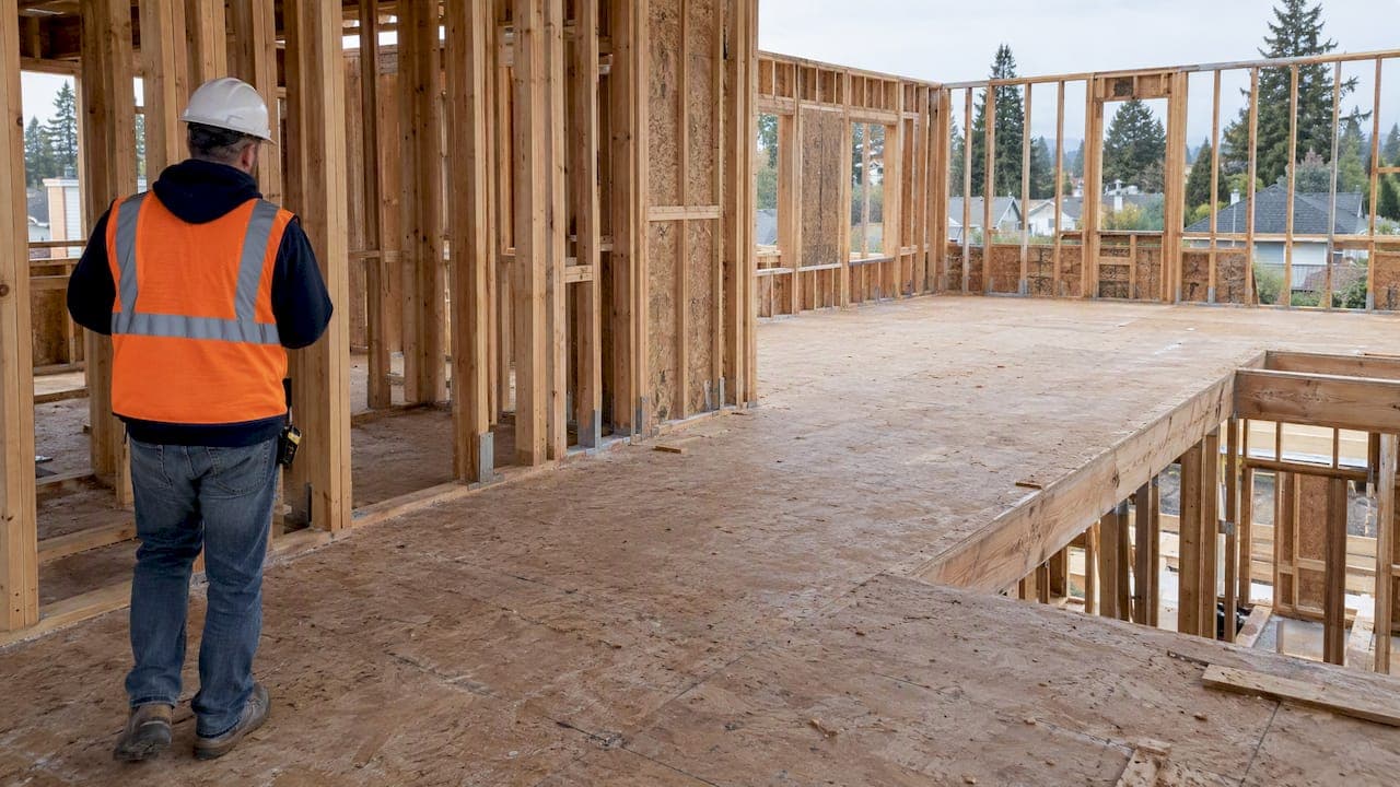
Torsional irregularity in a wood building occurs when seismic forces cause one edge of a diaphragm to drift noticeably more than the opposite edge, usually because the center of mass and center of rigidity do not line up. The check that matters is the torsional irregularity ratio (TIR), comparing maximum edge drift to the average edge drift at each story. When that ratio climbs past the thresholds in ASCE 7, additional design steps kick in. Run the per-story TIR check first, then confirm your diaphragm stiffness assumptions and accidental torsion application before trusting the result.
TL;DR:
- Buildings with large openings or asymmetric wall layouts are more prone to exceeding the TIR thresholds of 1.2 or 1.4, triggering design and detailing updates.
- Modeling diaphragm stiffness as either rigid or semirigid, and running both scenarios, helps identify the worst-case torsional response to inform design decisions.
- Cross-referencing TIR thresholds from ASCE 7 with code-specific eccentricity definitions is essential to avoid misinterpretation of irregularity severity.
- Once torsional irregularity exceeds thresholds, shear forces concentrate near the shortest walls, increasing demands on hold-downs, connectors, and wall capacity.
- Mitigation strategies include redistributing walls, improving diaphragm continuity, and verifying load paths through detailed shear wall analysis tools.
Table of Contents
- What torsional irregularity means: formulation and mechanics
- Code triggers and common check methods for torsion
- Causes and modeling choices specific to wood framing
- A practical workflow for checking torsional irregularity
- What changes in design when torsion governs
- Mitigation and retrofit strategies worth considering
- A worked-method example and documentation notes
- Balancing code checks with engineering judgment
- Organizing torsion-related shear wall checks with ShearWise Pro
- Sources
- FAQ
What torsional irregularity means: formulation and mechanics
TIR is calculated as ΔMAX divided by ΔADVE, where ΔMAX is the largest story drift measured at any point along the diaphragm edge and ΔADVE is the average of the drifts at the two extreme edges of the structure in that direction. Both terms come from the same load case, typically the seismic design force applied with accidental eccentricity, and both are read at the same story and direction.
The twist itself comes from eccentricity between the center of mass, where inertial forces act, and the center of rigidity, where the lateral system resists them. When those two points coincide, the diaphragm translates without rotating. When they do not, the diaphragm rotates around the center of rigidity, and the walls farthest from that center see the largest displacement.
Torsional stiffness and translational stiffness are not the same property. A building can have ample translational stiffness, meaning it resists straight-line sway, while remaining torsionally flexible if its shear walls sit close together in plan. Diaphragm behavior governs how much of that rotation actually reaches the walls: a stiff diaphragm redistributes shear efficiently, while a flexible one lets local drift concentrate near openings and corners.

Code triggers and common check methods for torsion
ASCE 7 classifies a story as torsionally irregular when TIR exceeds 1.2, and extremely torsionally irregular above 1.4. Crossing 1.2 typically triggers the torsional amplification factor Ax, which increases the design eccentricity used in subsequent force calculations. Crossing 1.4 can affect the redundancy factor ρ and may restrict the analysis methods permitted for that structure.
SDPWS guidance addresses how light-framed diaphragms behave between the idealized extremes of rigid and flexible, offering apparent shear stiffness values that support a semirigid model when a rigid assumption would understate edge drift.
Three things trip up practitioners regularly:
- Applying rigid-diaphragm assumptions to long, narrow, or heavily perforated diaphragms where semirigid behavior governs.
- Borrowing thresholds from other codes, such as IS 1893, without checking that the underlying eccentricity definitions and accidental torsion terms match ASCE 7's.
- Treating a passing TIR ratio as proof the load path is sound, when the ratio says nothing about collector continuity or wall-line capacity.
Thresholds built for one code's eccentricity formulation do not transfer cleanly to another. Keep the check and the code it came from paired.
Causes and modeling choices specific to wood framing
Wood buildings generate plan eccentricity through familiar culprits: garage door openings on one street-facing wall, large window walls on a daylight side, asymmetric interior wall placement, and cantilevered floor or roof diaphragms that shift mass away from the supporting walls below. Large openings tend to dominate this picture more than furniture or minor mass offsets, so an opening-layout audit is a reasonable first move before reaching for more complex redistribution fixes.
In two-story construction, checking each floor independently can miss the governing mechanism. Shaking-table research on two-story timber houses found that torsional response at one story interacts with the story above or below it, with damage sequencing altering the building's modal shape as the test progressed.
- Nail and fastener slip reduces apparent diaphragm shear stiffness well below a theoretical rigid value, and SDPWS calibration (Ga values) accounts for this directly.
- Rigid diaphragm models suit compact, well-connected floor plans with few openings.
- Semirigid models fit most residential wood diaphragms, where nailing and panel configuration meaningfully affect stiffness.
- Flexible diaphragm assumptions apply to long, narrow, or heavily cut diaphragms where edge drift varies sharply across the plan.
Pro Tip: When diaphragm stiffness is uncertain, run both a rigid and a semirigid model and carry the higher TIR forward as the governing case.
A practical workflow for checking torsional irregularity
A repeatable sequence keeps the check consistent from project to project and gives reviewers something to follow.
- Set up the model. Assign mass at each diaphragm level, choose a diaphragm stiffness idealization (rigid, semirigid, or flexible) based on plan geometry and SDPWS guidance, and apply accidental torsion cases with the amplification factor Ax initially set to 1.0.
- Compute edge drifts. Pull story drift at the two extreme edges of the diaphragm in each direction, under the load combination that includes accidental eccentricity.
- Calculate TIR. Identify ΔMAX and ΔADVE at each story and direction, then divide to get the ratio for that story.
- Interpret and act. A ratio at or below 1.2 generally closes the check. Above 1.2, apply Ax and recheck forces. Above 1.4, revisit wall layout, diaphragm continuity, or capacity before relying on a generic amplification factor alone.
- Run sensitivity checks. Vary diaphragm stiffness and accidental eccentricity assumptions to find the worst-case amplification, then document the assumptions and results that drove the final design.
Treating this as a one-pass calculation invites trouble. DeBock's review of ASCE 7-16 torsion provisions found the generic ratio check generally conservative, but noted cases where it missed important load-path behavior, particularly in torsionally flexible systems or those relying on orthogonal lines of lateral resistance. A ratio that passes is a starting point, not a closing argument.
What changes in design when torsion governs
Once TIR crosses the trigger threshold, the consequences show up at the element level rather than staying an abstract ratio. Shear tends to concentrate in the shortest wall segments nearest the center of rigidity's farthest edge, which means panel shear strength at those segments needs a second look rather than a system-average check.
- Overturning demand rises at the walls carrying the redistributed shear, which increases hold-down forces at those locations.
- Collector and chord forces increase because more of the diaphragm's shear is funneling toward fewer effective wall lines.
- Crossing the extreme irregularity threshold can trigger redundancy factor ρ penalties, which raise required wall capacity across the affected story.
- Connection detailing, strap sizing, and collector splices need to preserve the load path through the now-uneven force distribution, not just the average case.
None of these are optional add-ons. They are the direct cost of carrying a torsionally irregular diaphragm into construction documents.
Mitigation and retrofit strategies worth considering
The cheapest fix is almost always a plan change made before anything is built: add a shear wall near the flexible edge, reposition an interior wall line to balance stiffness, or shrink an oversized opening that is pulling the center of rigidity away from the center of mass.
- Rebalance wall distribution so the center of rigidity moves closer to the center of mass rather than relying solely on amplification factors.
- Improve diaphragm continuity with better chord and collector detailing, and lay out straps and struts to maintain a direct load path across openings.
- Review FEMA P-50 and P-1100 guidance for retrofit situations involving cripple walls, garages, or hillside dwellings, which FEMA flags as common soft or weak story conditions requiring strengthening or higher design shear.
- Escalate to refined modal analysis when the structure depends on orthogonal lateral lines or shows torsionally flexible behavior that a generic ratio check cannot capture.
Pro Tip: Audit opening layout before reaching for a redistribution fix. Most eccentricity in wood houses traces back to a garage door or a daylight wall, not furniture loads.
A worked-method example and documentation notes
A compact version of the workflow looks like this on an actual project, such as the East Coast Warehouse Renovation with a Solid Wood Spiral Staircase that illustrates multi-story timber work and related plan irregularity considerations:
- Assign mass at each floor and roof level, then choose a semirigid diaphragm model justified by panel layout and nailing per SDPWS.
- Run the accidental torsion case and extract edge drifts at each story.
- Compute TIR per story and direction, flagging any story above 1.2.
- Rerun with a stiffer and a softer diaphragm assumption to bound the amplification, and note which assumption governs.
Document every assumption, from diaphragm idealization to the eccentricity value used, in a form a reviewer can check without rebuilding the model. A review-ready package typically includes a wall-line summary table, hold-down and chord force summaries, and the governing TIR by story. A focused shear-wall calculation tool can speed these repeatable checks without sacrificing that documentation trail, particularly across multiple similar wood-framed projects.
Balancing code checks with engineering judgment
A TIR ratio under 1.2 with a well-distributed wall layout is usually enough to close the check. Large openings, cantilevered diaphragms, or eccentricity that stacks in the same direction across stories are red flags that deserve a second model run, not a quick sign-off. Document the reasoning behind each decision; reviewers and permitting staff can follow a clear assumption trail far more easily than a bare passing number.
— Evalin
Organizing torsion-related shear wall checks with ShearWise Pro
Once torsional irregularity pushes extra demand onto specific wall segments, keeping hold-down forces, collector sizing, and story drift results organized across every wall line gets harder to do by hand. A focused shear-wall calculation tool can organize shear wall calculations, openings, full-height segments, hold-down forces, transfer straps, and story drift checks for 1-story and 2-story wood buildings, then export a clean PDF report built for review coordination.

Fitting into the workflow above means running your governing TIR case, then letting the platform organize the wall-line, hold-down, and chord outputs that follow from it. Try the three-report trial or browse the tutorial library to see the report format before committing to a plan.
Sources
- ASCE 7-16 provisions for lateral drift determination (Structure Magazine commentary)
- 2021 SDPWS errata (American Wood Council)
- Experimental study on torsional behaviour of two-story timber houses (IITK WCEE paper)
- FEMA P-50 simplified assessments for detached single-family wood-frame dwellings
FAQ
What is torsional irregularity and how does it occur?
Torsional irregularity occurs when seismic forces cause a diaphragm to rotate because the center of mass and center of rigidity do not align, producing unequal drift at opposite edges. It is measured with the TIR ratio, comparing maximum edge drift to average edge drift at each story under ASCE 7.
What is torsional irregularity as per IS 1893?
IS 1893:2016 checks torsional irregularity using static eccentricity plus an accidental eccentricity term tied to floor-plan dimension, comparing maximum to average diaphragm displacement in a similar way to ASCE 7. The two code approaches differ in their eccentricity formulations, so thresholds from one should not be applied under the other without checking the underlying clauses.
What are the different types of structural irregularities?
Structural irregularities generally fall into plan irregularities, such as torsional irregularity, reentrant corners, and diaphragm discontinuity, and vertical irregularities, such as soft or weak stories and discontinuous shear walls. FEMA P-50 guidance flags cripple walls and garage stories as common vertical irregularities in wood dwellings.
What is torsion in buildings and what causes it?
Torsion in buildings is the rotational response of a diaphragm under lateral load, caused by eccentricity between the center of mass and the center of rigidity. In wood construction, large openings, asymmetric wall placement, and cantilevered diaphragms are common causes, and a parametric study of bracing distributions found torsional influence ranging from around 15% for symmetric layouts to 60% or more for highly asymmetric ones.
How is torsional irregularity checked in a wood structure?
The check computes per-story TIR by dividing maximum edge drift by average edge drift under an accidental torsion load case, then comparing the result to the 1.2 and 1.4 thresholds in ASCE 7. Diaphragm stiffness assumptions, calibrated per SDPWS, materially affect the result and should be tested with both rigid and semirigid models.