
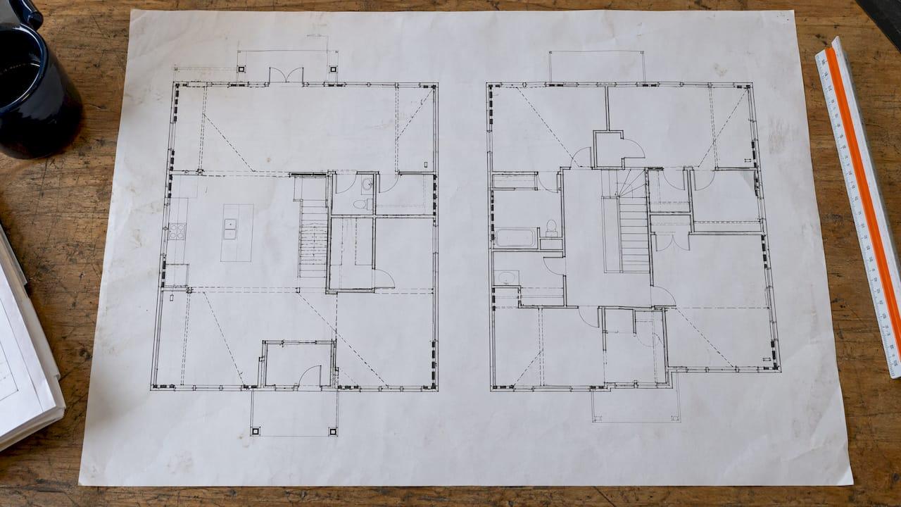
A bracing plan sheet is the drawing that shows how a wood-framed building resists lateral loads. It identifies the bracing method, the braced wall lines, the location and length of each braced wall panel, and the connections that carry load from the roof to the foundation. Plan reviewers reject sheets that leave these items out. This guide covers what belongs on the sheet, how to mark it, and how to check it before you submit.
TL;DR
- A complete sheet shows the bracing method, braced wall lines, panel locations and lengths, connections, and a continuous load path to the foundation.
- Dimension every required panel length on the plan, and label braced wall lines with numbers in one direction and letters in the other.
- Panel rules to verify: a panel starts within 10 feet of each line end, and adjacent panel edges are no more than 20 feet apart.
- In California, Oregon and Nevada, the local jurisdiction sets the design assumptions. Bakersfield projects should confirm them with the city or county.
- When the layout falls outside prescriptive limits, you need engineered shear walls, not a bracing sheet.
Table of Contents
- What a bracing plan sheet must show
- Marking braced wall lines and panels
- Reading dimensions, symbols and notes
- Panel, fastening and hold-down details to check
- California, Oregon, Nevada and Bakersfield
- Is your layout complete and consistent?
- Bracing sheet or shear wall plan?
- Prepare your sheet and report together
- FAQ
- Sources
What a bracing plan sheet must show
The International Residential Code (IRC) requires braced wall lines to be identified on the construction documents. It also requires pertinent information such as the bracing methods, the location and length of braced wall panels, and the foundation requirements at the top and bottom of each panel. Larimer County's braced wall guide cites this as IRC Section R106.1.3.
Jurisdictions turn that into checklists. Larimer County, Colorado, lists these items for its wall bracing plan:
- The bracing method.
- Braced wall line locations and spacing.
- Panel locations and lengths on each line.
- Wall and floor diaphragm connection details.
- A continuous load path from the top of the wall to the foundation.
- Return panels or hold-downs at the ends of braced wall lines.
The county states that plans lacking proper wall bracing information will not be accepted.
Oregon asks for more. The Oregon Building Codes Division Plan Review Guide calls for connections to the roof, floor and foundation, engineered truss information, and header, beam and post locations and sizes. It also asks for the attachment method (such as hardware and hold-downs), the portal frame type, and any shear walls.
A practical sheet therefore carries:
- A cover-page block of design assumptions: wind speed, exposure, Seismic Design Category, stories, construction type.
- A floor plan for each story with braced wall lines drawn and labeled.
- Panel callouts with method, length and wall height.
- Hold-down, strap and anchor callouts.
- A legend and general bracing notes.
Marking braced wall lines and panels
Braced wall lines
The Applied Building Technology Group defines a braced wall line as a straight line through the building plan that represents where wall bracing provides lateral resistance. Its wall bracing guide adds that the actual wall and panels need not fall exactly on the dotted line, as long as the offset rules are met. Interior walls can serve as braced wall lines. That helps you reduce the bracing required on exterior walls or keep line spacing within limits.
The City of Scappoose, Oregon, asks you to identify lines by numbers in one plan direction and letters in the other. It also allows panels to be offset up to 4 feet from the line. Its normal parallel line spacing is no more than 25 feet, and adjustment factors can extend that to 30 or 35 feet.
The IRC sets the spacing between parallel braced wall lines at a maximum of 60 feet, and intermediate lines through the interior are permitted.

Braced wall panels
Per IRC Section R602.10.2.2, as stated in the same Larimer guide:
- A panel begins within 10 feet of each end of a braced wall line.
- The distance between adjacent panel edges along the line is no more than 20 feet.
The Botetourt County guide adds that each line needs at least two panels, unless the line is 16 feet or shorter, where one panel of at least 48 inches is permitted. The cumulative panel length must meet or exceed the code-required length. The City of Santa Rosa handout states the same 16-foot rule under CRC R602.10.2.3.
These are model code limits. Local amendments and the method you choose can change them, so check the adopted edition.
Reading dimensions, symbols and notes
Read the legend first. Then read dimensions as written and never estimate them. A structural drawing guide from Xometry warns that mixing metric and feet-and-inches units on one project causes calculation errors. Finally, read the notes for material grades, standards and procedural requirements.
On a bracing sheet, three habits catch most problems:
- Add the dimension strings. Outer strings give overall length and inner strings give opening sizes and wall locations. If they do not add up to the overall, stop and resolve it before framing, as an exam-prep study guide advises.
- Match every panel callout to a wall that exists on the floor plan, including its height and opening sizes.
- Keep one unit convention across all sheets.
WoodWorks notes that shop drawings may write dimensions in feet-inches-sixteenths, so 12'-2 1/4" appears as 12-02-04. Its detailing presentation also lists what to verify: species, member sizes, sheathing thickness, fastener spacing and type at shear walls, posts or load-transfer mechanisms, and blocking.
If your team marks up PDF plans for review, a calibrated scale matters for any measurement taken off the sheet. This PDF scale calibration guide covers how to verify scale before you measure.
Panel, fastening and hold-down details to check
Published jurisdiction handouts show the type of detail reviewers expect. They are examples from specific codes, not universal values.
- Sheathing and blocking. St. Louis County's basic bracing method requires 7/16-inch or thicker plywood or OSB, blocked vertical joints, and blocked horizontal joints in braced wall panels.
- Minimum panel width. The same county lists 32 inches at 8-foot wall height, 36 inches at 9 feet, 40 inches at 10 feet and 48 inches at 12 feet for plywood or OSB panels at a 3:1 aspect ratio. Its simplified portal walls are 16, 18, 20 and 24 inches at a 6:1 ratio.
- End restraint. The county requires an 800-pound hold-down securing the end stud to the foundation, unless a 24-inch full-height sheathed wall is placed 90 degrees to the end. The APA System Report SR-102 uses the same logic for continuous sheathing: a 24-inch return corner or an 800-lbf hold-down at the end stud.
- Connections. Braced wall lines connect to foundations, floor framing and roof framing per CRC R602.10.8.
- Plate washers. Calistoga's criteria call for plate washers of at least 0.229 by 3 by 3 inches between the sill plate and nut, except where approved anchor straps are used, per CRC R602.11.1.
Panel width depends on wall height and sheathing choice. For help sizing sheathing, see our wall sheathing thickness guide. Sheathing type also affects panel stiffness, which this OSB and plywood comparison discusses for subfloor use.
California, Oregon, Nevada and Bakersfield
There is no single statewide bracing sheet. Each city or county sets its own design assumptions, so confirm them with the building department.
California examples show the pattern. Calistoga's 2025 Building Design Criteria says conventional construction under the 2025 California Residential Code typically uses Seismic Design Category D2, with a minimum ultimate design wind speed of 110 mph. Santa Rosa asks designers to state assumptions on the cover page: lateral system, wind speed, exposure, Seismic Design Category, stories, construction type, occupancy and story height.
Calimesa's adoption of the 2025 CRC amends Table R301.2 to show Seismic Design Category D1, D2 or E. It also requires continuous footings under braced wall panels in categories D0, D1, D2 and E.
Oregon reviewers use the Building Codes Division guide cited above. For Nevada, and for Bakersfield in Kern County, we did not find a published bracing sheet standard to cite here. Ask the plan check counter which code edition, seismic category and wind speed apply to the parcel, then put those values in your cover-page block.
Is your layout complete and consistent?
The City of Boise Wall Bracing Checklist is a good model for a self-check. It asks whether:
- All braced wall lines are identified.
- Lines are spaced at 60 feet or less.
- Panel locations, lengths and methods are on the plans.
- Each panel meets the minimum length for the adjacent clear opening height per IRC Table R602.10.4.2.
- Required panel lengths are dimensioned on the plan.
Add these checks:
- Every line has the required number of panels.
- Panel lengths on the plan match the notes and schedule.
- Hold-downs and straps appear on both the plan and the detail sheet.
- The load path is traceable from roof to foundation at each line.
- Upper and lower story lines align or have a transfer detail.
Our guides on shear wall layout checks and CRC braced wall rules go deeper on each.
Bracing sheet or shear wall plan?
The APA says prescriptive design resists lateral forces with wall bracing at prescribed locations instead of shear walls. Bracing serves the same function but is limited to low-load situations. An example location rule is bracing at each end and not more than 25 feet on center.

Shear wall design follows engineering calculations. A Penn State housing research paper notes that shear wall panel minimums generally range from 4 to 8 feet with no openings, and that walls with openings may be segmented, perforated or use force transfer around openings.
If the plan has large openings, tall walls or irregular layouts that exceed prescriptive limits, an engineered shear wall plan is the route. Read braced wall versus shear wall and the IRC braced wall method to decide which applies.
Our view on bracing sheets
Most rejected bracing sheets fail on organization, not on engineering. The wall line is unlabeled, a panel length is missing, or the hold-down on the plan does not match the detail. Those are bookkeeping errors, and they cost a review cycle.
We built ShearWise Pro around that problem for 1-story and 2-story wood buildings. Wall lines, openings, full-height segments, hold-down forces, transfer straps, roof information and story drift checks live in one project, and the output is a clean PDF report for review coordination. We designed it as a focused workflow rather than a general-purpose structural package, so a residential designer spends time on the layout instead of on the tool.
A sheet is only as good as the numbers behind it. Keep the calculation and the drawing in step.
Evalin
Prepare your sheet and report together
If you produce engineered shear wall layouts for 1- and 2-story wood buildings, ShearWise Pro organizes the calculations and exports a PDF report to attach to your plan set. The trial includes three watermarked reports at $0. Paid access is $29 per month or $250 per year on the plans page.

See how the numbers are checked in the validation library, or sign up to try ShearWise.
FAQ
What is a bracing plan sheet?
It is the plan sheet that shows how a wood-framed building resists wind and seismic loads. It identifies braced wall lines, panel locations and lengths, the bracing method, and the connections that complete the load path. Reviewers use it to confirm code compliance.
Does every house need one?
Permit offices generally expect bracing information on residential plans. Larimer County, for example, will not accept plans that lack it. Check your local department for the form it requires.
How far apart can braced wall lines be?
The IRC allows a maximum of 60 feet between parallel lines. Some local guides, such as Scappoose's, use 25 feet as the normal limit, with adjustments allowed to 30 or 35 feet.
When do I need shear wall calculations instead?
When the building exceeds prescriptive limits, the lateral system must be engineered. That means calculating shear wall segments, hold-downs and drift rather than selecting bracing at prescribed locations.
Sources
- Larimer County Residential Construction Plan Submittal Checklist
- Larimer County Braced Wall Design
- Oregon Building Codes Division Plan Review Guide
- Applied Building Technology Group IRC Wall Bracing Guide
- Botetourt County Wall Bracing Guide
- Santa Rosa Residential Conventional Braced Walls
- Xometry: How to Read Structural Drawings
- OpenExamPrep: Plans, Elevations, Sections and Details
- WoodWorks Detailing Considerations for Offsite Building Components
- St. Louis County Basic Bracing Methods
- APA System Report SR-102
- Calistoga Building Design Criteria 2025
- Calimesa Chapter 15.35, 2025 California Residential Code adoption
- City of Boise Wall Bracing Checklist
- APA Design Guide: Introduction to Lateral Design
- Penn State: Shear Wall Design in Residential Construction
- OSB vs. Plywood Subfloor
- Calibrate PDF Scale for Subcontractors