
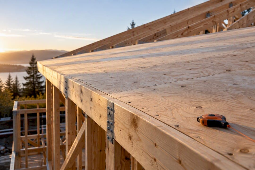
Diaphragm chords act as the flanges of a beam. You size their axial demand with T = M/d, the diaphragm bending moment divided by its depth, then select a chord member and connections that deliver that force into collectors and vertical elements. The modeling method you choose (equivalent beam versus a corrected model with spring supports) changes where peak chord force lands, and material choice drives everything downstream, from ACI splice rules to strap fastener counts.
TL;DR:
- Diaphragm chord forces are typically calculated using T = M/d, with M as the maximum bend moment and d as the diaphragm depth, but modeling assumptions can shift these forces significantly.
- Rigid support models tend to overestimate chord continuity, so adopting models with spring supports better captures force redistribution, especially in flexible or irregular diaphragms.
- Openings larger than half the diaphragm span often require sub-diaphragm design to prevent force concentration and maintain load path integrity across discontinuities.
- Proper placement and reinforcement of chords differ by material: outer quarter placement in concrete, boundary members in wood, and steel connections with appropriate fasteners and welds.
- ShearWise Pro assists with wall, shear, and transfer element calculations but does not directly perform chord force analysis, serving as a helpful organization tool for the diaphragm shear wall portion.
Table of Contents
- What Is Diaphragm Chord Design and How Do You Model It?
- How Do You Calculate Chord Forces Step by Step?
- How Do You Detail Chords in Concrete, Wood, and Steel?
- How Do Collectors and Drag Struts Transfer Diaphragm Shear?
- Why Does Chord Continuity Matter Around Openings and Level Changes?
- Common Chord Detailing Mistakes and How to Avoid Them
- Worked Example: Roof Diaphragm Chord Design Step by Step
- Author Perspective: Practical Judgment Calls and When to Be Conservative
- ShearWise Pro: Faster Documentation for the Shear Wall Side of Your Diaphragm Project
- Sources
- FAQ
What Is Diaphragm Chord Design and How Do You Model It?
Diaphragm chord design starts with a modeling decision, and that decision determines every number you calculate afterward. Most practicing engineers reach for the beam analogy first: treat the diaphragm as a horizontal beam spanning between shear walls or frames, with the roof or floor sheathing acting as the "web" resisting shear, and the chords acting as the "flanges" resisting bending. This framework comes directly from FEMA's beam-analogy guidance, which treats chord force as F = M/d in the simplest case.
The beam analogy assumes plane sections remain plane. That assumption holds reasonably well for diaphragms with a length-to-depth ratio under roughly 3:1 or 4:1, where the diaphragm behaves close to a deep beam. Once a diaphragm gets long and narrow, or picks up irregular reentrant corners, that assumption starts to break down, and the simple flange model can misstate where the true tension and compression peaks occur.
Two modeling refinements matter in practice:
- Equivalent beam with rigid supports treats the shear walls or frames as unyielding, which simplifies hand calculation but can overstate chord continuity across supports.
- Corrected equivalent-beam models with spring supports account for the actual stiffness of the vertical elements, redistributing moment and shifting the chord force envelope, particularly at interior supports.
- Sub-diaphragm modeling becomes necessary when a large opening or an interrupted chord line breaks the primary diaphragm into smaller load paths that need their own moment and chord check.
The CRSI Seismic Design Guide walks through both the rigid and spring-supported approaches with worked examples across seismic design categories, and it's worth having open next to your own calculation the first few times you run this.
Diaphragm rigidity changes chord continuity behavior in a way that trips up engineers moving from steel or concrete framing into wood. A rigid diaphragm distributes shear to vertical elements in proportion to their relative stiffness, similar to how a rigid floor diaphragm behaves in a concrete building. A flexible diaphragm, common in wood-framed construction, distributes shear more like a simple-span beam between walls, tributary area by tributary area. That distinction determines whether your chord behaves as continuous across multiple spans or as a series of simple spans that each need their own peak moment check. It also determines whether you need to enforce continuity across a change in floor elevation or a stepped diaphragm, where the chord force at the discontinuity can spike well above what a smooth, single-span model would suggest.
Research on large flexible diaphragms has documented cases where collective chord behavior differs from the simple flange model, particularly where distributed reinforcement or multiple parallel chord elements share load in ways the single-flange assumption doesn't capture. If your diaphragm has an unusual aspect ratio, multiple offsets, or a plan shape a code example doesn't resemble, that's a signal to check your model assumptions before trusting the T = M/d number at face value.
How Do You Calculate Chord Forces Step by Step?
Chord force comes from one relationship: T = M/d, where M is the diaphragm bending moment and d is the diaphragm depth measured between chord lines. Getting a defensible chord force means getting M and d right, then applying the formula with attention to which moment governs and where openings shift the distribution.
Start with the moment. For a simply supported diaphragm under uniform lateral load w (in pounds per foot along the diaphragm span), the maximum moment at midspan is M = wL²/8, where L is the diaphragm span between shear walls. That's the same expression industry seminar materials use when walking engineers through sample roof diaphragm calculations, and it should look familiar from any simple-beam analysis you've run before.
Here's the calculation sequence to follow every time:
- Establish the lateral load per foot (w) from your seismic or wind force distribution, tributary to the diaphragm span under consideration.
- Determine the diaphragm span (L) between the vertical elements that support it, and the diaphragm depth (d) measured perpendicular to the span, chord to chord.
- Compute the design moment, typically M = wL²/8 for a simple span, but use the actual peak moment from your model if the diaphragm is irregular, continuous over multiple supports, or interrupted by a large opening.
- Divide moment by depth: T = M/d gives you the axial tension (and equal compression) demand on the chord.
- Compare against subdivided regions if openings or offsets exist, checking a sub-diaphragm moment (often expressed as T = wL²/(8d) for the local segment) rather than only the global value.
- Select the chord member or reinforcement sized for that axial force, then verify the connection can develop it.
Chord forces in typical wood roof diaphragms commonly range over a wide spectrum of values depending on span, load, and diaphragm depth, according to the beam-analogy guidance FEMA compiles. A short-span, lightly loaded diaphragm might land at 3,000 to 5,000 pounds; a long-span commercial roof under higher seismic demand can push past 20,000 pounds at a single chord splice, which is exactly the kind of number that should make you double-check your hold-down and strap selection before it goes on a permit set.
One caution worth flagging early: the beam analogy gives an upper-bound elastic estimate. It does not automatically apply amplification or overstrength factors the way some seismic force paths do elsewhere in a building. Don't reflexively multiply a chord force by an overstrength factor unless your governing code section specifically calls for it at that location. Confirm this against the applicable ASCE/SEI provision for your project rather than assuming the amplification rules from a different lateral element carry over.
How Do You Detail Chords in Concrete, Wood, and Steel?
Chord detailing changes completely depending on material, even though the underlying axial demand (T = M/d) stays identical across all three.
Concrete diaphragms place chord reinforcement most effectively in the outer quarter of the slab depth, which reduces interference with other reinforcing mats and helps control flexural cracking at the diaphragm edge. That's the placement practitioners commonly favor, and it lines up with the NIST NEHRP guide's derivation of chord tension and compression as Tu, Cu = Mu/d. You have a choice between a concentrated chord bar (a discrete bundle of bars at the slab edge) and distributed chord reinforcement spread over a wider band. Distributed reinforcement changes the local shear distribution along the chord line, so if you go that route, carry the revised shear pattern through your collector check rather than assuming the concentrated-bar shear diagram still applies. Confinement matters at compression chord zones, and ACI's diaphragm provisions set limits on effective reinforcement stress and require specific splice and confinement detailing to keep that compression zone from local crushing under cyclic seismic demand. Mechanical splices need to develop the full chord force across the joint, not a reduced value, since a splice location often lands right where the peak moment occurs.
Wood diaphragms typically use the top plate, a rim board, or a dedicated boundary member as the chord element, sized and connected according to ANSI/AWC SDPWS shear capacity tables. Hold-down selection at chord splices and wall intersections needs to match the calculated tension demand exactly, not the nearest hardware size rounded up casually. Strap layouts across a ridge, a hip, or a floor-to-floor splice carry that same tension across the discontinuity, and fastener patterns for straps and collectors need nail or screw counts that develop the strap's rated capacity without splitting the framing member. A detailed walkthrough of wood shear wall chord design for uplift covers hold-down selection and fastener layout in more depth if you're working through your first permit set with unusual uplift demand.
Steel-framed diaphragms, often built with a metal deck over steel framing, typically use an edge angle, a ledger, or the spandrel beam itself as the chord element. Weld detailing gives you continuity but demands careful sequencing and inspection access; mechanical fasteners (bolts or powder-actuated pins into a ledger) simplify field installation but need a documented capacity per fastener that you can trace back to a manufacturer's tested value. Choose based on erection sequence and inspection access as much as on raw capacity, since a weld that can't be inspected properly in the field is a liability regardless of its calculated strength.
Across all three materials, keep chord reinforcement or connection hardware clear of other congested details, mechanical penetrations, or slab edge forms. A chord that has to dodge a plumbing sleeve at the exact location of peak moment is a detail that needs resolving on the drawings, not in the field.

How Do Collectors and Drag Struts Transfer Diaphragm Shear?
Collectors gather diaphragm shear along a wall line and deliver it into the vertical elements, which is a fundamentally different job from what a chord does even though the two elements often sit close together in a diaphragm layout. A chord resists bending at the diaphragm edge; a collector, sometimes called a drag strut, collects shear from the diaphragm span and drags it into a shear wall, brace frame, or moment frame that doesn't extend the full length of the diaphragm edge.
The NIST NEHRP guide describes two collector strategies: a discrete collector beam or reinforced band, or a distributed collector spread into the slab itself over a wider width. Spreading the collector into the slab reduces peak reinforcement congestion at any single location but requires you to confirm the slab can develop that shear over the assumed spread width, particularly near the wall face where the collector force concentrates.
Sizing a collector comes down to a few limits working together:
- Tension and compression capacity of the collector cross-section must exceed the calculated axial demand from the tributary diaphragm shear it collects.
- Average reinforcement stress limits in concrete collectors keep the reinforcing steel from yielding prematurely under the full seismic demand, per ACI's diaphragm provisions.
- Shear-friction checks at the collector-to-wall interface confirm the connection can actually transfer that collected force into the vertical element rather than slipping.
- Anchor development and mechanical splice capacity need to match the peak collector force, not an averaged or reduced value.
Pro Tip: Congested nodes at wall corners, where a chord, a collector, and a hold-down all want reinforcing or hardware in the same six inches of framing, are the single most common source of field change requests. Flag these locations on your drawings early and confirm bar or fastener spacing works in three dimensions, not just in plan.
Partial-depth collectors, common where a wall doesn't extend the full diaphragm depth, need a documented load path showing how force gets from the full diaphragm depth down to the partial-depth collector without an unresolved gap. If you're detailing a complex opening or discontinuity near a collector line, the case study library AMV MasterSap maintains walks through several strut and chord configurations around openings that are worth cross-referencing against your own layout.
Why Does Chord Continuity Matter Around Openings and Level Changes?
Chord continuity keeps the load path intact, and losing it shifts your peak chord force to a location your original model never checked. A continuous chord distributes tension and compression smoothly along its length; a discontinuous one, interrupted by a large opening, a stair, or an elevation change, forces the load to find a new path, often concentrating force at the discontinuity edge rather than at the location your simple-span model predicted.
Cross-ties matter here in two distinct ways. They restrain out-of-plane wall forces by tying the wall back into the diaphragm, and they provide continuous tension ties between chord segments across the diaphragm width so the whole assembly acts as a single connected system rather than a series of disconnected panels. Skipping a cross-tie at an interior line is one of the more common ways a diaphragm that calculates fine on paper underperforms in the field.
Openings larger than roughly half the diaphragm's plan dimension in either direction typically require their own sub-diaphragm design. That means:
- Treating the region around the opening as its own smaller diaphragm with its own chord and collector elements.
- Reinforcing the diaphragm edge around the opening to carry the redirected shear and moment.
- Verifying the sub-diaphragm ties back into the main diaphragm's load path without a gap in chord continuity.
Run a continuity checklist across any elevation change or step in the diaphragm: confirm the chord force at the step transfers into the framing below, confirm a cross-tie or strap physically bridges the discontinuity, and confirm your model's assumed support condition (rigid or spring) still matches the as-built framing at that location. A wood building lateral system guide is useful background if you want to see how chords, collectors, and shear walls interact as a full system rather than as isolated elements.
Common Chord Detailing Mistakes and How to Avoid Them
Most chord failures in the field don't come from an undersized member. They come from a connection that never got the calculated force from the drawing into the actual framing.
Splice locations landing exactly at a peak moment point is the single most preventable error. If your model shows peak chord tension at midspan, don't let the framing plan or the contractor's material layout put a butt splice right there without a matching mechanical splice or lap detail sized for the full force. Fastener pattern integrity matters just as much: a strap or hold-down rated for a given capacity only delivers that capacity with the full nail or screw count driven correctly, and a field substitution of fewer or smaller fasteners quietly erodes the calculated capacity without anyone flagging it on a change order.
Reinforcement congestion at wall corners and collector intersections is the other recurring problem. When a chord bar, a collector bar, and hold-down anchor bolts all want the same six-inch strip of concrete or the same top plate, something has to move, and it's better if you decide what moves on the drawings rather than the field crew deciding under time pressure.
Build your inspection checklist around these items:
- Verify chord and collector reinforcement placement matches the drawing before slab pour or sheathing cover-up.
- Confirm hold-down and strap fastener counts against the schedule, not against a visual "close enough" check.
- Check splice locations against the moment diagram, not against convenient framing layout.
- Document assumptions for hold-down capacity, chord modeling method, and any sub-diaphragm boundaries directly on the permit set, so a reviewer isn't guessing at your load path.
Pro Tip: Reviewers move faster on a set that shows the chord force calculation and the corresponding hardware selection side by side on the same sheet. A reviewer who has to hunt through a calculation package to match a number to a strap callout is a reviewer who sends the set back with questions.
Worked Example: Roof Diaphragm Chord Design Step by Step
Consider a rectangular roof diaphragm, 60 feet long by 40 feet deep, spanning between two parallel shear walls at the 40-foot ends, under a uniform seismic lateral load of 200 pounds per linear foot along the 60-foot span.
- Set up the load and span. Diaphragm span L = 60 feet, diaphragm depth d = 40 feet, uniform load w = 200 lb/ft.
- Compute the maximum moment. For a simple span, M = wL²/8 = (200 lb/ft × 60 ft²) / 8 = (200 × 3,600) / 8 = 90,000 lb·ft.
- Compute the chord force. T = M/d = 90,000 lb·ft / 40 ft = 2,250 lb.
- Select the chord member. A double top plate or a continuous rim board sized per ANSI/AWC SDPWS capacity tables can typically carry this demand with a standard strap splice at each panel joint; confirm the specific species and grade capacity against your framing plan.
- Size the splice connection. Select a strap rated at or above 2,250 pounds tension, with a fastener count (nails or screws) on each side of the splice sufficient to develop that rated capacity per the manufacturer's published values.
- Check the sub-diaphragm condition. If a skylight or roof opening interrupts the chord line, isolate that region and recompute T = wL²/(8d) using the local span and depth of the affected sub-diaphragm rather than the global values.
- Verify connection development. Confirm the strap's fastener schedule develops the full 2,250-pound demand, and check that the hold-down at the wall end develops the transferred chord and collector forces without relying on the sheathing nailing alone.
- Check drift and deflection implications. Confirm the diaphragm deflection under this load doesn't create incompatibility with the rigidity of the attached vertical elements, particularly if you assumed a rigid-support model in step 2.
A roof diaphragm this size, under this load, produces a chord tension at a level typical for such conditions, a number that sits comfortably within standard strap capacity ranges but still needs a documented fastener count on the drawing rather than an assumed "standard strap" callout. Scale the same six-step sequence up to a longer span or heavier load, and you'll see chord forces climb into the five-figure range quickly, which is exactly where hold-down selection stops being routine and starts requiring a specific engineered connector. A full step-by-step roof diaphragm worked example walks through a comparable calculation with additional detailing callouts if you want a second reference point before finalizing your own drawing set.
Author Perspective: Practical Judgment Calls and When to Be Conservative
Continuous chords are the right default whenever the framing allows it. A simple-span assumption is easier to calculate, but it also hides how a real diaphragm redistributes force once one segment cracks or yields slightly before another. I lean conservative on irregular plan geometry, offset shear walls, or any load path that doesn't match a textbook rectangle. That means running the sub-diaphragm check even when the opening looks borderline, and documenting the modeling method (rigid versus spring support) on the calculation package itself.
Reviewers trust a set that shows its assumptions. Write down why you chose an equivalent-beam model over a corrected one, and a reviewer spends less time guessing and more time confirming your math.
— Evalin
ShearWise Pro: Faster Documentation for the Shear Wall Side of Your Diaphragm Project
Diaphragm chord calculations are only half the lateral design package on a wood-framed job. The shear wall side, wall lines, openings, full-height segments, hold-down forces, and transfer straps, still needs its own organized calculation set and a clean report a reviewer can actually follow. ShearWise Pro is built specifically for that half of the workflow on 1- and 2-story wood buildings, so you're not rebuilding a spreadsheet from scratch every time a wall line changes.

Some software tools organize wall line layouts, openings, shear segments, hold-down forces, and transfer strap requirements into a structured calculation, and combine roof information and story drift checks into a single project file. They can export reviewer-friendly PDF reports designed for permit coordination, which help document chord and collector details alongside shear wall calculations. Such tools do not replace engineering judgment on modeling method or chord continuity, but can assist with organizing calculations and formatting reports.
Try it with the three-report trial at no cost, or move straight to a Professional Monthly plan at $29 per month if you're already running multiple wood-framed projects through review. An annual plan is also available at $250 per year for the same access. Sign up to try ShearWise Pro on your next 1- or 2-story wood project and see how it fits alongside your chord and collector calculations.
Sources
Every chord calculation eventually needs to trace back to a code provision, and the reference set for diaphragm chord design is narrower than most engineers assume, once you know which document covers which piece.
- Seismic design of cast-in-place concrete diaphragms, chords, and collectors: A guide for practicing engineers (NIST GCR 10-917-4)
- FEMA / beam-analogy diaphragm guidance (university-hosted extract)
- CRSI Seismic Design Guide (table of contents and chapter references)
Run these specific checks against whichever reference governs your material: chord axial capacity against the calculated T = M/d demand, required reinforcement area or member size against that same demand, development and splice length at any interruption in the chord line, collector average stress against ACI's limit, and shear-friction capacity at every collector-to-wall connection.
One interpretation issue worth knowing about before it surprises you mid-project: ASCE's standards-exchange discussion has flagged errata concerns around a factor in one of the diaphragm design expressions, including debate over whether a 0.8 factor was applied correctly in an earlier printing. When a code equation produces a chord force that looks inconsistent with your hand-checked M/d value, check for published errata before assuming your own math is wrong. Code commentary is explanatory, not mandatory; when commentary and mandatory text seem to disagree, the mandatory provision governs, and the commentary tells you why it was written that way.
FAQ
What Is the Formula for Diaphragm Chord Force?
Chord force is calculated as T = M/d, where M is the diaphragm bending moment and d is the diaphragm depth between chord lines. This beam-analogy approach comes from FEMA's diaphragm guidance and gives an upper-bound elastic estimate that still requires a connection-adequacy check.
When Should You Use a Corrected Equivalent-Beam Model Instead of Rigid Supports?
Use a corrected model with spring supports whenever the vertical elements supporting the diaphragm have meaningfully different stiffnesses, since a rigid-support assumption can overstate chord continuity across those supports. The CRSI Seismic Design Guide walks through both approaches with worked examples across seismic design categories.
Where Should Chord Reinforcement Be Placed in a Concrete Slab?
Chord reinforcement is commonly placed in the outer quarter of the slab depth to reduce interference with other reinforcing and control flexural cracking at the diaphragm edge. This placement lines up with the chord tension and compression derivation in NIST's NEHRP guide.
How Do Openings Affect Diaphragm Chord Design?
Openings larger than roughly half the diaphragm's plan dimension typically require their own sub-diaphragm design, with a dedicated chord and collector around the opening edge. That sub-diaphragm still needs to tie back into the main diaphragm's load path without breaking chord continuity.
Can ShearWise Pro Help With Diaphragm Chord Calculations?
ShearWise Pro focuses on shear wall calculations, wall lines, hold-downs, and transfer straps for 1- and 2-story wood buildings rather than performing chord force calculations directly. It's useful as a companion tool for organizing the shear wall side of a project and generating reviewer-friendly PDF reports while you handle chord and collector design separately, with plans starting from a free three-report trial.