
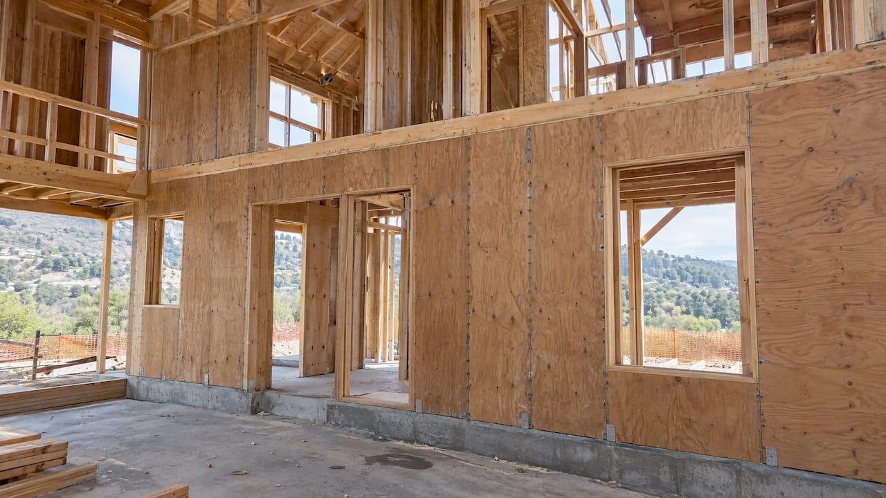
A high wind shear wall is a fully sheathed wood wall designed to carry lateral wind load from the roof and floor diaphragms down to the foundation. It must also resist overturning and uplift at its ends. In a 1- or 2-story wood building, getting it right means five things: a continuous load path, correct wall-line shear, hold-downs sized for overturning and uplift, sound treatment of openings, and a drift check. This guide walks through each one, with code notes for California, Oregon and Nevada.
TL;DR
- Wind load travels from roof and floor diaphragms into shear walls, then through connectors into the foundation. Every link has to be designed.
- Hold-downs at wall ends resist overturning. Uplift anchorage and continuity must carry through each story.
- Openings, segment aspect ratios and sheathing nailing change wall capacity. Check them wall line by wall line.
- Strength is not enough. Verify story drift as well.
- CA, OR and NV all point wind design to ASCE/SEI 7 through the building code. Confirm local wind speed and exposure with the jurisdiction.
Table of Contents
- What a shear wall does in high wind
- How wind load reaches the foundation
- Code basis in California, Oregon and Nevada
- Combined shear and uplift
- Openings, segments and hold-downs
- Drift: the check that is easy to skip
- Our perspective
- Setting up a high-wind shear wall package
- Run the numbers in ShearWise Pro
- FAQ
- Sources
What a shear wall does in high wind
A shear wall is a vertical diaphragm. According to APA, it carries lateral load from its top along its bottom into the shear wall below or the foundation. It is not a bearing wall with a different label. Its job is to resist racking, and that stiffness comes from sheathing, fasteners and boundary elements such as hold-downs, as Lynn Engineering explains.
For exterior walls, the Building America Solution Center guide disallows intermittent bracing and calls for fully sheathed wood structural panels. That is the baseline for high wind work: continuous structural sheathing, nailed to a schedule you can defend on the plans.
How wind load reaches the foundation
Wind pushes on the walls and roof. Roof and floor diaphragms act as horizontal beams and transfer that load to the vertical shear walls. From there, the load passes through framing connections (bolts, straps, brackets) into the foundation and the ground, as described in this lateral design lecture from the University of Michigan. The same source treats connections as the critical links: if one fails, the load path for that section fails with it.
For high-wind wood systems, reThink Wood describes the load path running from the roof through diaphragms, shear walls, connectors, fasteners and framing to the foundation and soil. Anchorage must resist overturning, uplift and sliding.

Oregon states this as a code requirement. Under the 2025 OSSC Chapter 16, walls that provide vertical load-bearing or lateral shear resistance must be anchored to the roof, all floors and the members that provide lateral support, with connections able to resist the prescribed horizontal forces. The same chapter requires a complete load path from the point of origin to the load-resisting elements.
A practical load path checklist
- Roof diaphragm to the top of the shear wall: nailing, blocking, and any collector or drag strap.
- Second-story wall to floor diaphragm: shear transfer at the floor line.
- Floor-to-floor uplift and overturning continuity: straps or hold-down rods through the floor system.
- First-story wall to foundation: sill plate anchorage, anchor bolt spacing, plate washers.
- Foundation: footing and stem wall capacity for the hold-down and anchor forces delivered to it.
Inspectors look at this hardware in the field. The HUD resilience guide notes that inspectors verify that hardware matches the approved plans, including plate washers and spacing. Your plans and reports should name each connector and its location clearly.
Code basis in California, Oregon and Nevada
All three states build on the International Building Code family and send wind loads to ASCE/SEI 7. The details differ by state and by jurisdiction.
| Topic | California | Oregon | Nevada |
|---|---|---|---|
| Wind load reference | 2025 CBC §1609.1.1 requires wind loads under ASCE/SEI 7 Chapters 26 to 30 | 2025 OSSC §1609.1.1 requires the same, using the §1609.3 basic wind speed | Adopted locally; see the Nevada guide linked below |
| Documentation | Wind speed and exposure per §1609 or ASCE 7 | §1603.1.4 requires V, VASD, risk category, exposure, internal pressure coefficients and C&C pressures on design documents | Reviewers check wall schedules, hold-downs and load path on plans |
| Wood shear wall capacities | Allowable ASD shear tables for wind and seismic, with AWC SDPWS for detailing | Same SDPWS basis | Same SDPWS basis |
Sources for the table: CBC 2025 Chapter 16 and OSSC 2025 Chapter 16. For Nevada, our guide to what reviewers check on Nevada plans covers the plan-review side.
Local wind speed and exposure
Wind speed is local. As one California example, Nevada County's 2025 design criteria cite ASCE 7-22 Chapters 26 to 31, list 2025 CRC values of VASD 85 mph and Vult 110 mph, and set Exposure B or C by building height, terrain and surface roughness. It also flags a special wind region east of Kingvale above 4,000 feet. A hillside lot and a flat valley lot in the same county can therefore carry different inputs.
For Bakersfield projects, do not assume a number from a neighboring county. Kern County sits near the Tehachapi wind corridor, so confirm the basic wind speed, risk category and exposure with the City of Bakersfield or Kern County building department before you lock the design. Then write the values on the plans. Our guide to wind pressure under ASCE 7 explains how those inputs become design pressures.

Wind does not always control
In much of California, seismic demand is the bigger issue. Simpson Strong-Tie's engineering blog warns that you cannot assume wind governs from base shear alone, because detailing and ductility differences often make seismic design more critical in specific configurations. Check both cases for each wall line. Our post on combined wind and seismic design for wood shear walls covers how to compare them.
Combined shear and uplift
High wind creates positive pressure on the windward side and negative pressure elsewhere. A New Zealand BRANZ bulletin notes that overturning is resisted by building weight, framing connections and foundation connections. In a light wood house, the weight is small, so connections do most of the work.
The design order is straightforward:
- Design the shear walls for the applied wind loads and find the unit shear along each wall line.
- Compute overturning at each wall end from the shear and wall height.
- Subtract the resisting dead load, using the load combination your code requires.
- Add uplift from roof tie-down forces where the load path passes through the wall.
- Size hold-downs and straps for the combined result, and carry the force down to the next level.
The AWC Perforated Shearwall Design guide states that uplift anchorage is required at each end of a perforated shear wall. It also states that a continuous load path to the foundation must be kept for overturning and uplift, including forces coming from stories above. In a 2-story building, that means the first-floor hold-down force includes what the second story delivers.
Openings, segments and hold-downs
Openings are where high wind shear walls usually get complicated. Garage fronts, large glazing and narrow piers between windows all reduce capacity or raise hold-down forces.
Segmented, perforated and force transfer around openings
- Segmented: each full-height segment resists its share of shear, and each needs hold-downs at both ends.
- Perforated: the wall is treated as one unit with openings, using adjustment factors. Uplift anchorage is still needed at each end.
- Force transfer around openings (FTAO): the wall is designed with boundary hold-downs and strapping around the openings. According to this engineering note on FTAO, FTAO can eliminate two or more hold-downs that segmented design would need.
The same note excludes piers above a 3.5:1 aspect ratio. SDPWS requires piers at least 2 feet wide, though the note allows 18 inches or more at an aspect ratio no greater than 3.5:1 with blocked panel edges. Read the note against the SDPWS edition your jurisdiction adopts before you use it.
Aspect ratio and blocking
Tall, narrow segments are less stiff. For seismic loads, SDPWS allows aspect ratios up to 3.5:1 when capacity is multiplied by 2W/H, as Strong-Tie's blog summarizes. California's published shear wall table gives separate allowable ASD capacities for seismic and wind and points designers to AWC SDPWS for aspect-ratio adjustments and apparent stiffness. Blocked panel edges also raise capacity; see our comparison of blocked and unblocked shear walls. Engineers should also review the footnote that affects SDPWS wind values before they finalize a schedule.
Hold-downs
As APA puts it, hold-downs are critical connections at shear wall ends that resist the overturning forces from wind. Choose them for the tension demand, then check the post size, the bearing and the anchor embedment that go with them. Show the model, the post and the anchor on the plans so the field matches the calculation.
Drift: the check that is easy to skip
A wall that passes strength can still fail serviceability. Strong-Tie notes that stiffness must be verified explicitly, because meeting strength requirements does not guarantee meeting drift limits. In a 2-story building, long openings on the first story are the usual place for drift to grow. Include the deflection check in the same package as the shear values, so a reviewer finds both together.
Our perspective
We built ShearWise Pro around one idea: residential 1- and 2-story wood projects need a focused workflow, not a general-purpose structural suite.
On high-wind jobs, the same questions come up on every plan. What is the shear on each wall line? Which segments count? Where do the hold-downs and transfer straps land? Does the drift check pass? Our platform is designed to organize those items in one place: wall lines, openings, full-height segments, hold-down forces, transfer straps, roof information and story drift checks.
The result is a clean PDF report you can hand to a reviewer. We think a reviewer should see the inputs, the results and the connector schedule without hunting. That is the standard we build to.
Evalin
Setting up a high-wind shear wall package
Whatever tool you use, the package should follow this order.
- Project inputs: code edition, risk category, basic wind speed, exposure, building dimensions and roof geometry.
- Wall lines: list each line on each story, with its length, height and tributary load.
- Openings and segments: identify full-height segments and their aspect ratios.
- Shear values: pick sheathing, nail spacing and blocking to meet the unit shear.
- Hold-downs and straps: size for overturning, uplift and transfer around openings.
- Drift: verify the deflection limit for each story.
- Report: export a PDF with the assumptions on the first page.
If you want more background on how load splits among walls, our lateral load distribution guide explains what determines each wall's share.
Run the numbers in ShearWise Pro
ShearWise Pro is an online shear wall calculator and report platform for 1- and 2-story wood buildings. It is made for engineers, architects, designers, drafters, contractors and builders who need organized calculations and reviewer-friendly PDFs. Our shear wall software page describes the workflow in detail.

Start with the free trial: three watermarked reports at $0. After that, Professional Monthly is $29 per month and Professional Annual is $250 per year. See plans on the program page or sign up to try ShearWise.
FAQ
What makes a shear wall a "high wind" shear wall?
There is no separate wall type. The wall is a standard wood structural panel shear wall, designed for higher wind demand. That usually means tighter nailing, blocked edges, larger hold-downs and a more carefully detailed load path. The wind speed, risk category and exposure on your site set the demand.
Which code governs wind loads on wood shear walls in California and Oregon?
Both the 2025 California Building Code and the 2025 Oregon Structural Specialty Code require wind loads to be determined under ASCE/SEI 7 Chapters 26 to 30. Shear wall capacities and detailing then follow AWC SDPWS. Your local building department confirms the adopted editions.
Do I need hold-downs on every shear wall?
Segmented walls need them at both ends of each segment. Perforated walls need uplift anchorage at each end of the wall. FTAO designs place hold-downs at the wall boundaries and can reduce the count. The calculation decides, so show the demand for each location.
Does wind or seismic control in California?
It depends on the building and the site. You should check both for each wall line rather than assume either one governs. Wind can control on a light, tall or open-front building in an exposed location, while seismic often controls elsewhere.
What wind values should I use for a Bakersfield project?
Use the basic wind speed, risk category and exposure that the City of Bakersfield or Kern County building department confirms under the adopted code. Put those values on the plans. Local terrain and nearby wind corridors can change the exposure category.
Sources
- Shear Walls & Diaphragms, APA
- Structural Sheathing in Exterior Walls, Building America Solution Center
- Shear Walls: What are they?, Lynn Engineering
- Design Guide: Introduction to Lateral Design
- Designing for High Winds, reThink Wood
- Oregon Structural Specialty Code 2025, Chapter 16
- California Building Code 2025, Chapter 16
- Building Codes and Design Criteria, Nevada County, California
- Table 2306.3(4) Wood Structural Panel Shear Walls
- Ignore Seismic Requirements When Wind Controls?
- Building Drift: Do You Check It?
- BRANZ Bulletin: Load Paths
- Perforated Shearwall Design, AWC
- Designing for Natural Hazards: Wind, HUD
- Design for Force Transfer Around Openings