
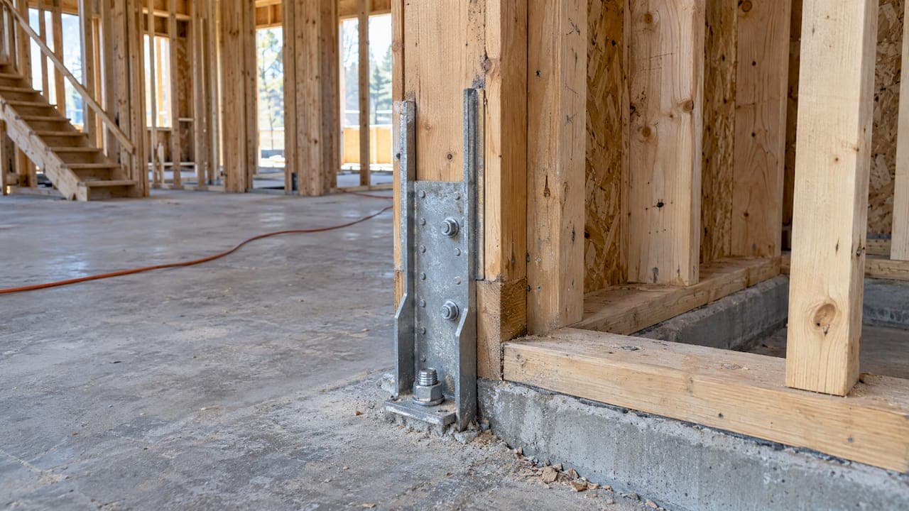
Holdown selection comes down to four checks: calculate the tension at the end of each shear wall segment, choose a connector whose evaluation-report capacity exceeds it, confirm the deflection and anchorage work with the rest of the system, and document it all for the reviewer. This guide walks through each check for 1-story and 2-story wood-framed buildings, with notes for projects in California, Oregon and Nevada, including Bakersfield.
TL;DR
- Start with the overturning tension at each wall end, using the effective moment arm from the end of the wall to the center of the holdown or tension rod.
- Select the connector from its valid evaluation report and the manufacturer's current literature, not from memory or an old catalog.
- Check the whole load path: post size, fasteners, wood properties, and anchor design to concrete under ACI 318 Chapter 17.
- Walls with openings need a force transfer method, and holdown forces at opening ends can differ from the wall ends.
- Keep a clean calculation record. Reviewers want the demand, the product, the capacity and the anchorage in one place.
Table of Contents
- Start with the demand: how holdown force is determined
- Match capacity and deflection to the demand
- Check the full load path
- Local code notes: California, Oregon and Nevada
- Verify product documentation before you specify
- A repeatable selection workflow
- Perspective
- Try the workflow on a real project
- What to put in the report for plan review
- FAQ
- Sources
Start with the demand: how holdown force is determined
A holdown resists the uplift at the end of a shear wall. The lateral load on the wall tries to rotate it, and the holdown holds the end post down. You size the connector for the tension that results, so every later step depends on getting this number right.
For a simple segment, the overturning moment is the unit shear times the wall length times the wall height. Dividing by the moment arm gives the chord tension. Dead load on the wall offsets part of the uplift, and the applicable load combinations decide how much credit you may take.
The moment arm matters more than most people expect. In the 2021 SDPWS, the arm used for overturning accounts for the distance from the end of the wall to the center of the holdown device or tension rod, as described in this SEAU presentation on wood shear walls. Using the full wall length instead of the effective arm understates the tension.

A quick worked example
This is an illustration with assumed numbers, not a project design.
- Unit shear on the segment: 400 plf
- Segment length: 8 ft
- Wall height: 9 ft
- Overturning moment: 400 × 8 × 9 = 28,800 lb-ft
- Assumed effective moment arm: 7.5 ft
- Gross tension before dead load relief: 28,800 ÷ 7.5 = 3,840 lb
Then you subtract the permitted dead load contribution for the governing load combination, and the remainder is the demand you take to the connector tables. On a 2-story building you also add the tension from the story above, because the lower holdown carries the cumulative uplift.
Walls with openings
Windows and doors change how force travels. Where you use the perforated method, the full-height segments carry the load. Where you want to use the wall length above and below the openings, a rational analysis is needed. The Diekmann technique is one such method for estimating force distribution and holdown forces around openings. APA research on force transfer around openings (FTAO) covers it, and this FTAO design guide explains the method.
The practical point: with FTAO, the holdown at an opening edge can see a different force than the one at a wall end. Check every full-height segment, not only the corners of the building. Our post on cutting hold-downs from six to two shows how wall line layout choices change the count.

Match capacity and deflection to the demand
With the tension known, you compare it against the connector's published allowable load. Three rules keep this step clean.
- Use the evaluation report. For projects reviewed by the Division of the State Architect (DSA) under the 2025 California Building Code, prefabricated connectors must be listed in a valid evaluation report and designed in accordance with that report, the manufacturer's literature, the code and DSA IR 23-1. Most residential work goes through a city or county rather than DSA, but the same discipline of tying each selection to a current report is a good habit everywhere.
- Apply the reduction where required. Under IR 23-1, evaluation-report capacities are used and 80% applies for seismic load combinations unless a Section 2.3 exception permits 100%. Confirm which factor your jurisdiction and load combination require before you compare numbers.
- Check deflection, not just strength. A holdown that carries the load can still stretch enough to push a wall past its drift limit. Story drift checks need the holdown's deflection at the design load. For rod systems, the SEAW white paper notes that under AC 316 the total rod-system vertical deformation should not exceed 0.20 inch per story or between restraints, whichever is more restrictive, unless the engineer of record shows drift and deformation compatibility are met. That is in the SEAW paper on threaded rod holdown systems. We cover how that limit plays out in a typical workflow in our 0.20 in rule post.
The same paper observes that drift often controls shear wall and tie-down design in wood buildings of five or more stories. For 1-story and 2-story homes, strength usually governs first, but a drift check still belongs in the file.
Pick the installation type that suits the framing
Holdowns come in bolted and screw-installed forms. Screw-installed models, such as the HDU series that uses SDS screws, are designed to reduce fastener slip and typically leave a greater net post section than bolts do, according to the manufacturer's connector catalog. Bolted models are an option where the post is a larger member or the detail calls for bolts through the stud pack.
Use this as a decision frame:
| Condition | Lean toward |
|---|---|
| Tight stud pack, need to keep net section | Screw-installed holdown |
| Low slip needed for drift | A model with a published low-deflection rating |
| Post or column with room for bolts | Bolted holdown |
| Installation raised above the sill | A model whose report allows it |
The last row is a reminder that the report limits where the connector sits. Always read the installation notes for the model you chose.
Check the full load path
The holdown is one link. Selection is not finished until the chain from the post to the foundation checks out.
Wood members and fasteners
IR 23-1 asks the designer to check wood-member specific gravity and maximum moisture content against the code, manufacturer and evaluation-report requirements, and to detail connections so splitting is minimized. A holdown rated on one species and grade does not carry that rating onto a weaker post. Confirm the post size, species and fastener schedule match the table you used.
Check that the end post can itself take the compression and tension. Our guide on designing chords for 1,653 lb of uplift walks through that member check.
Anchorage to concrete
The holdown anchor needs its own design. IR 23-1 states that holdown anchors must comply with ACI 318 Chapter 17. Los Angeles guidance says the engineer of record must design anchors to concrete or masonry, specifying bolt grade, embedment and edge distance, and must also check the wood members and footing capacity. The City of Los Angeles research report lays out that requirement. Edge distance is the item that most often catches designers on narrow footings and garage returns.
Shrinkage and multi-story accumulation
For taller buildings, the SEAW paper says plans should specify per-story cumulative tension, shrinkage allowances and rod-system deformation limits, and that shrinkage devices are often included in designs of four or more stories. That is beyond most 1-story and 2-story work, but the habit of listing cumulative tension per story carries over directly. If you work with continuous rods, see our guide to hold-down rods in multi-story wood buildings.
Local code notes: California, Oregon and Nevada
Code adoption dates and amendments change, so confirm them with the building department that will review your plans. A few anchors help:
- California. Local jurisdictions apply the California Building Standards Code. As one example of how the cycle shows up locally, Nevada County, CA states that projects submitted on or after January 1, 2026 must comply with the 2025 California Building Standards Code (Nevada County Building Codes and Design Criteria). Note this is a county in California, not the state of Nevada.
- Bakersfield and Kern County. Check the city or county building division's current adopted code and any local amendments before you finalize a selection.
- Oregon and Nevada. Each state runs its own adoption cycle, and local amendments are common. Check the state and jurisdiction pages for the edition in force on your submittal date.
Whatever the jurisdiction, the evaluation report and the manufacturer's current literature are the documents the reviewer will compare your selection against.
Verify product documentation before you specify
Catalog values change between editions, and a substitution on site can undo your design. Do these three things every time:
- Pull the current evaluation report and manufacturer literature for the model.
- Note the report number and the catalog edition on the plans or calculation sheet.
- Add a plan note that substitutions need approval from the designer.
Manufacturer catalogs say the same thing. Their wood construction connector catalog advises consulting a qualified design professional when using the products and verifying with the designer before substituting a replacement product (2024-2025 connector catalog). Contractors and builders reading this: do not swap a holdown for a similar-looking one without the engineer's sign-off.
A repeatable selection workflow
Here is the sequence we use as a checklist for each wall line.
- Define wall lines and list every full-height segment.
- Enter unit shear for each segment from the lateral analysis.
- Calculate overturning with the effective moment arm, then subtract allowed dead load.
- Add tension from the story above for lower-level walls.
- Run the opening method you chose (perforated or FTAO) and note the forces at opening ends.
- Choose a connector whose evaluation-report capacity covers the demand, with the seismic factor your code requires.
- Check deflection against your drift assumptions.
- Check the post, fasteners and anchor design.
- Record the product, report number and capacity in the report.
Doing this by hand across a dozen wall lines is where transcription mistakes creep in. A structured tool keeps the segments, demands and connectors in one table. Our structural calculator guide shows what that looks like in practice.
Perspective
Most holdown mistakes we see are not math errors. They are bookkeeping errors: a demand calculated for one segment and a connector chosen for another, a story-above tension that never got added, or a catalog value copied from an old edition.
That is why we built ShearWise Pro around a narrow job: 1-story and 2-story wood-framed buildings. When the software only has to cover wall lines, openings, full-height segments, hold-down forces, transfer straps, roof information and story drift checks, the workflow stays short and the output stays readable.
Our claim is simple. A focused tool lets you organize the whole holdown story in one place and hand a reviewer a clean PDF, instead of a stack of spreadsheets and hand sketches. General-purpose structural software can do more, but for residential wood work you often need less, faster, and with every number traceable.
We would rather you trust the result because you can see how it was built. That is the reason the validation library exists, with worked calculation examples you can compare against your own checks.
Evalin
Try the workflow on a real project
ShearWise Pro is an online shear wall calculator and report platform for engineers, architects, designers, drafters, contractors and builders working on 1-story and 2-story wood buildings. It organizes wall lines, openings, full-height segments, hold-down forces, transfer straps, roof information and story drift checks, then exports PDF reports for review coordination.
The trial gives you three watermarked reports at $0, so you can run a real wall line before you commit. After that, Professional Monthly is $29 per month and Professional Annual is $250 per year. See the plans and trial, sign up to try ShearWise, or look at the validation library first to compare worked examples with your own numbers.
What to put in the report for plan review
Reviewers read dozens of submittals. Make yours quick to check.
- A wall line layout showing segments and opening locations.
- The unit shear, overturning moment, moment arm and dead load credit for each holdown.
- The connector model, evaluation report number and allowable load.
- The demand-to-capacity ratio for each holdown.
- Anchor design notes: bolt grade, embedment, edge distance.
- A drift check summary and the deflection assumption for the holdown.
- A plan note on substitutions.
If you are comparing software options, look for output that carries these items without extra formatting work. Our software page for residential wood buildings shows how ShearWise Pro presents them.
FAQ
How do I calculate the holdown force for a shear wall?
Multiply the unit shear by the wall segment length and height to get the overturning moment, then divide by the effective moment arm. Subtract the dead load credit your load combination permits and add any tension from the story above. For walls with openings, use a method such as the Diekmann technique to find the forces at opening ends.
Can I use the full catalog allowable load for seismic design?
Not always. Under DSA IR 23-1, evaluation-report capacities are used and 80% applies for seismic load combinations unless an exception permits 100%. Check which rule your jurisdiction applies and read the evaluation report for the specific model.
What is the difference between a bolted and a screw-installed holdown?
Screw-installed models such as the HDU series use SDS screws to reduce fastener slip and typically leave a greater net post section than bolts do. Bolted models suit larger posts or columns where the detail calls for through bolts. Choose based on the post, the deflection you need and the installation limits in the report.
What else must I check besides the holdown itself?
Check the wood member's specific gravity and moisture content, the fastener schedule, and the end post capacity. Design the anchor to concrete under ACI 318 Chapter 17, including bolt grade, embedment and edge distance, and check the footing as well.
Can a contractor substitute a different holdown on site?
Only with the designer's approval. Connector manufacturers advise verifying with the designer before substituting a replacement product, because capacity, deflection and installation requirements differ between models.
Sources
- Design for Force Transfer Around Openings (FTAO)
- Wood Shear Walls, SEAU presentation
- DSA IR 23-1: Prefabricated Wood Construction Connectors, 2025 CBC
- SEAW White Paper 9: Threaded Rod Holdown Systems in Wood Frame Buildings
- City of Los Angeles research report, 2017 LABC
- Wood Construction Connectors catalog 2021-2023, HDU and DTT load tables
- Nevada County, CA: 2025 Building Codes and Design Criteria
- Wood Construction Connectors catalog 2024-2025