
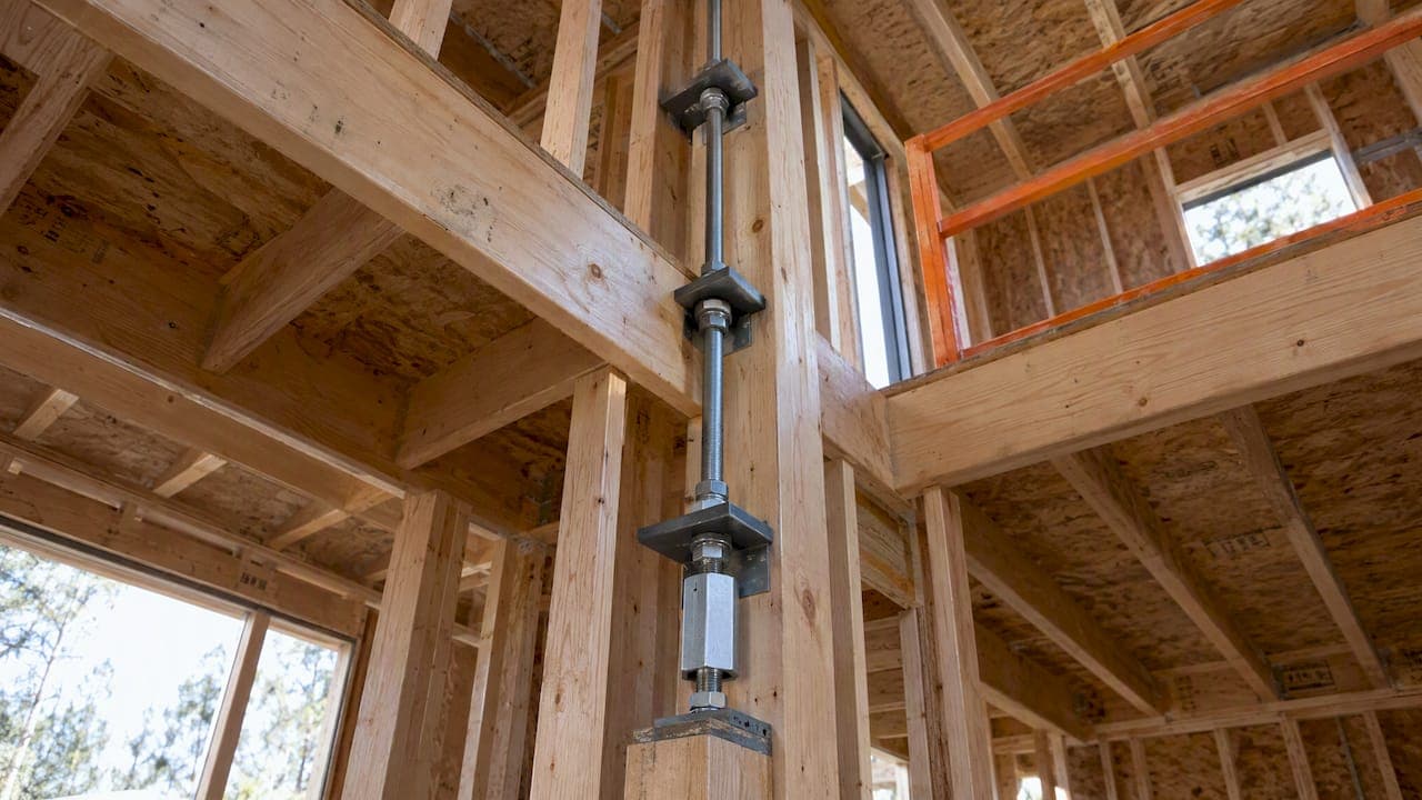
A continuous rod tie-down system is a stack of threaded rods, couplers, bearing plates, nuts and shrinkage take-up devices that carries the cumulative overturning tension from shear wall end posts down to the foundation. Engineers use it when conventional hold-downs stop being practical, and the whole design depends on three things: accurate cumulative loads, a controlled deformation budget, and clear drawings. This guide walks through each one, with the checks reviewers and inspectors tend to look for.
TL;DR
- A continuous rod system collects tension from each story's shear wall boundary posts and transfers it through rods and bearing plates to the foundation.
- The main parts are threaded rod, coupler nuts, bearing plates and shrinkage-compensation devices. Wood shrinks; steel rod does not.
- Check rod elongation plus take-up device deflection against the system's per-story limit, and include it in your story drift check.
- The engineer of record (EOR) specifies rod grades, plates, posts and anchorage, and shows cumulative loads and shrinkage allowances on the plans.
- Inspection focuses on rod and coupler engagement, bearing plates, blocking, embedments, and activated take-up devices before enclosure.
Table of Contents
- What a continuous rod tie-down system does
- Components and where they sit
- Designing the system for a shear wall
- Elongation, shrinkage and the 0.20 inch limit
- Installation and shrinkage take-up
- Inspection checklist
- Code and local review in California, Oregon and Nevada
- Perspective
- Where ShearWise Pro fits
- FAQ
- Sources
What a continuous rod tie-down system does
When wind or seismic load pushes on a shear wall, the wall tries to overturn. One end post goes into tension, the other into compression. On a one-story building, a single hold-down handles that. On a taller wood building, the tension from each story stacks on the story below, and the load has to reach the foundation somehow.
A continuous rod system does this with an assembly of rods, bearing plates, nuts and take-up devices. According to a manufacturer's seismic and wind catalog, the system collects the cumulative tensile loads from each floor's shear wall boundary posts and moves them downward through the rods into the foundation.
The rod does not carry load by itself. End posts deliver load to bearing plates, the plates bear on the sole or sill plates, and the bearing load becomes tension in the rod. Each link in that chain has its own capacity, and the weakest one governs.

Why not just stack hold-downs?
A conventional hold-down has a ceiling. One technical bulletin that ranks for this topic is not something we rely on here, so use the SEAW guidance instead: for structures four stories or taller, the SEAW white paper on threaded rod holdowns notes that cumulative holdown forces and deformations may exceed what conventional connectors and straps can handle, while threaded rod systems offer higher design capacities and can provide shrinkage compensation.
The skipped-restraint problem matters too. A manufacturer's engineering blog explains that when restraints are omitted, load travels up through the framing until it is restrained, which can raise shear wall stiffness and create drift concerns. Tying off at each level keeps the load path where the designer intended.
Components and where they sit
A typical assembly has four kinds of parts, each with a clear job.
| Component | What it does | What the designer controls |
|---|---|---|
| Threaded rod | Carries cumulative tension between restraint points | Diameter, steel grade, net tensile area |
| Coupler nuts | Join rod segments floor by floor | Coupler type and engagement |
| Bearing plates | Spread load across sole or sill plates and into the rod | Plate size, steel bending, wood bearing |
| Shrinkage-compensation devices | Close gaps as wood shrinks and settles | Device type, deflection allowance |
The catalog lists threaded rods, coupler nuts, bearing plates and shrinkage-compensation devices as the core set. In a multi-story wood building, the end posts deliver shear wall loads to the bearing plates and rods for overturning restraint.
There is also a difference between two applications. A manufacturer's flier describes one product line for shear wall overturning restraint and a separate one for roof uplift. Do not treat them as interchangeable on the plans: label which function each rod line serves.
Bearing plates deserve a closer look. Per the manufacturer's technical notes, they spread loads across sole or sill plates to limit wood crushing and plate bending, and they transfer bearing loads into rod tension. Check both the steel bending and the wood bearing, not just one.
Designing the system for a shear wall
What the EOR specifies
The SEAW guidance says the engineer of record should set the system criteria: rod diameters and steel grades, bearing plates, compression posts, shrinkage devices and couplers. Concrete anchorage is also the EOR's job, and it should be shown on the drawings.
What the plans must show
The same paper lists what plans need to provide:
- Shear wall and holdown locations.
- Cumulative tension and compression loads per story.
- Shrinkage and consolidation allowances per story.
- Rod-system deformation limits, if required.
If you leave any of these off, the installer or the supplier's system designer has to guess, and plan check will ask. Our guide on shear wall plan check comments covers how to get ahead of those questions, and the shear wall schedule checklist shows how to keep wall data consistent from sheet to sheet.
Verifying capacities
According to the catalog, engineers must verify that design loads do not exceed component capacities, check building drift, size bearing plates for steel bending and wood bearing, and specify the anchorage and foundation design. That is a short list, but each item needs its own line in the calculations.
A practical worksheet for each rod line:
- Cumulative tension at each story, from the boundary posts of every wall stacked on that line.
- Rod capacity at the selected diameter and grade.
- Bearing plate check on the sill or sole plate.
- Compression post check at the opposite end of the wall.
- Anchorage into the foundation, designed by the EOR.
- Elongation and take-up device deflection per story.
For the wall-level inputs that feed this worksheet, see our guide to hold-down rods in multi-story wood buildings.
Elongation, shrinkage and the 0.20 inch limit
Rods stretch under load. The manufacturer's guide says elongation depends on load, rod length, net tensile steel area and the modulus of elasticity of steel. Use the net tensile area, not the gross area, for elongation calculations. Using gross area understates stretch.
The catalog adds that rod elongation and shrinkage-compensating-device deflection should be considered when verifying building drift.
Then there is the per-story limit. The same guide states that AC316 limits rod elongation plus take-up device deflection to 0.20 inch per story or between restraints, whichever is more restrictive, using allowable stress design. The SEAW paper says the same about AC316: a maximum total vertical deformation of 0.20 inches per story or between restraints under ASD. Both sources allow the EOR to exceed it by demonstrating compliance with story drift and deformation compatibility requirements (IBC 1604.4 in the manufacturer's wording).

A worked way to read the limit
Say a rod line runs through two stories with a restraint at each floor. The limit applies to each span between restraints. For each span you add two numbers: elongation of the rod length in that span, calculated with net tensile area, and the deflection of the take-up device at that level. If the sum is 0.20 inch or less, the system fits the default limit. If it is more, you either upsize the rod, shorten the unrestrained length, or document why the larger value is acceptable for drift and compatibility.
The result then goes into the story drift check. Hold-down slip and rod stretch both increase wall deflection, so they cannot be left out of the drift number. Our article on the 0.20 in rule for shear wall holdowns and SDPWS steps goes through that sequence for typical residential walls.
Installation and shrinkage take-up
The manufacturer's flier describes its anchor tie-down system as installed floor by floor as the structure goes up. Take-up devices mitigate wood shrinkage, and the designer specifies the studs, posts, blocking, anchorage and foundation.
The reason for take-up devices is simple. As the engineering blog puts it, continuous steel rods do not shrink with wood, so without a device a gap forms as the lumber dries and settles. A gap means the wall can lift before the rod picks up load, which adds to drift.
Practical points for the drawings and the field:
- Show the shrinkage allowance per story so the supplier can select devices.
- Call out blocking and compression posts at each rod location.
- Note that rod segments are coupled as each floor is framed.
- Require take-up devices to be activated before the wall is enclosed.
Inspection checklist
A 2008 inspection guide lists what to verify on site:
- Rod grade and coupler engagement.
- Bearing plates, nuts and washers.
- Compression wood and blocking.
- Embedments.
- Nailing per the shop drawings.
- Specified compensators installed square, within the manufacturer's offset limits, activated before enclosure, and with expansion clearance.
- Header-to-trimmer gaps no more than 1/64 inch.
The same guide warns that skew, dirt, insufficient expansion clearance, inactive devices, gaps, deficient blocking and misplaced embedments can cause binding, system-integrity problems or improper load transfer. Most of these are visible only before drywall or sheathing closes the wall, so schedule the inspection with that in mind.
If plans change in the field, record it. Reviewers expect clear as-built records for shear wall changes, especially where a rod line moves.
Code and local review in California, Oregon and Nevada
Continuous rod systems sit in a gray area of the codes. The TUCC policy from the ICC Tri-Chapter Uniform Code Committee says there are no industry standards for these systems, and it recommends confirming the guideline's acceptance with the local building department. That is the practical rule for any jurisdiction, including Bakersfield and other California, Oregon and Nevada offices: ask early how the plan reviewer wants the system documented.
The same TUCC guideline calls for calculations showing that shear wall drift and the applied loads transfer through all tie-down components to the foundation or a rigid base. In other words, the reviewer wants to see the full chain, not just a rod size.
To make that chain readable:
- Put cumulative loads per story on the plans.
- State the deformation limit you used and the result.
- Show the anchorage detail and the foundation connection.
- Reference the system's evaluation report if you use a proprietary assembly.
Anchorage at the foundation is its own topic. See the anchor bolt layout code guide for sill-level requirements that sit next to the rod embedment.
Perspective
We built ShearWise Pro around residential one-story and two-story wood buildings, and that shapes how we see continuous rods.
On most of these projects the first question is whether a rod system is needed at all. Often it is not: good wall layout, full-height segments placed with intent, and sensible aspect ratios can cut the number of hold-downs before anyone orders hardware. That is why we organize wall lines, openings, full-height segments, hold-down forces and transfer straps in one place. When you can see every wall line's demand together, you can tell early whether a rod line is justified or whether a conventional hold-down will do.
When a rod line is justified, the paperwork matters as much as the steel. Reviewers want cumulative loads, drift numbers and clear callouts. We designed our story drift checks and PDF reports to put that information where a plan checker looks for it, so fewer comments come back.
Evalin
Where ShearWise Pro fits
ShearWise Pro is an online shear wall calculator and report platform for one-story and two-story wood-framed projects. It helps you organize wall lines, openings, full-height segments, hold-down forces, transfer straps, roof information and story drift checks, then export a clean PDF report for review coordination. The results give you the demand numbers that go into your rod or hold-down decision.
You can start with the three-report trial at $0, which produces watermarked reports. After that, Professional Monthly is $29 per month and Professional Annual is $250 per year. See the plans and pricing page, or sign up to try ShearWise.
If you want to see how calculations are laid out before you commit, the validation library has worked shear wall examples.
FAQ
What is the difference between a continuous rod tie-down and a conventional hold-down?
A conventional hold-down anchors one story's post to the framing or foundation below. A continuous rod system ties the stacked tension from several stories into one rod line down to the foundation. The SEAW paper notes that for buildings four stories or taller, cumulative forces can exceed conventional connector capacity, which is where rod systems are used.
Do continuous rods shrink with the wood frame?
No. Steel rod keeps its length while lumber dries and settles, so gaps can open at bearing plates. Shrinkage-compensation devices take up that movement. Your plans should show a shrinkage allowance per story so the right devices are selected.
What is the deformation limit for a rod system?
The AC316 criteria cited by both the manufacturer and SEAW limit rod elongation plus take-up device deflection to 0.20 inch per story or between restraints under ASD. The EOR may exceed that by demonstrating compliance with story drift and deformation compatibility requirements. Use net tensile area for the elongation calculation.
Who designs the foundation anchorage?
The engineer of record. SEAW guidance says concrete anchorage should be designed by the EOR and shown on the drawings, along with rod diameters, grades, plates, posts, devices and couplers.
Will my building department accept a continuous rod system?
Acceptance varies. The TUCC policy recommends verifying with the local building department, so contact the plan reviewer before finalizing the detail and ask what documentation they want for cumulative loads and drift.
Sources
- Strong-Rod Systems seismic and wind catalog (manufacturer)
- Strong-Rod Systems seismic and wind restraint flier (manufacturer)
- Strong-Rod Systems technical notes (manufacturer)
- Continuous rod restraint systems for multi-story wood structures (engineering blog)
- SEAW paper: Threaded rod holdown systems in wood frame buildings
- Rod tie-down systems inspection guide
- TUCC policy 12: shear wall continuous tie-down