
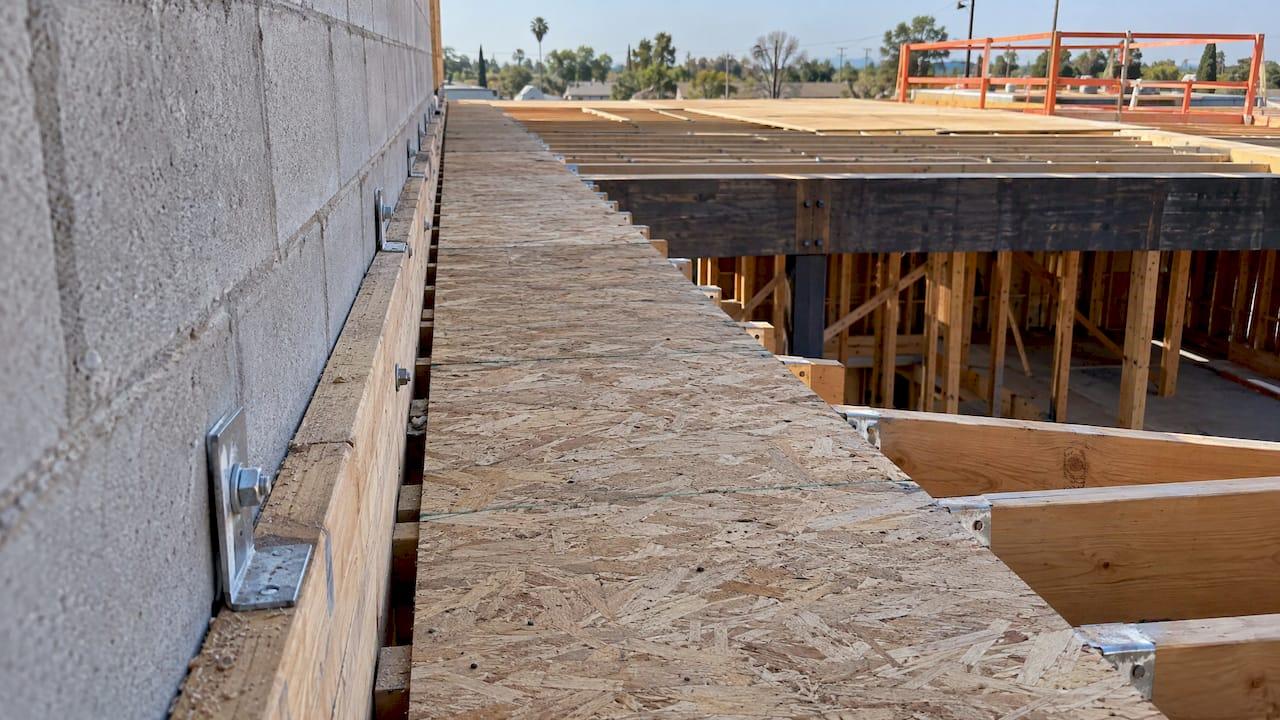
A subdiaphragm is a small diaphragm inside the main roof or floor diaphragm. Its job is to collect wall-anchorage forces and deliver them to continuous cross-ties, so you do not have to run a full-width tie from every anchor. NIST's guide to wood light-frame diaphragm seismic design describes it this way. Designing one comes down to four decisions: the anchorage force, the strip geometry, the chord and tie forces, and the path into the shear walls. That last decision is where the work meets your shear wall calculations, and where ShearWise Pro keeps wall lines, hold-downs and transfer straps organized for 1- and 2-story wood buildings.
This guide is for engineers, designers and drafters on residential and light-frame projects in California, Oregon and Nevada, including Bakersfield.
TL;DR
- A subdiaphragm delivers local wall-anchor forces to continuous cross-ties, so closely spaced anchors do not each need a full-width tie.
- Design it as a simply supported strip under distributed anchorage load, then check shear, sheathing and nailing, chords, and connection forces.
- Keep the length-to-width ratio within 2.5:1 when the subdiaphragm is part of a continuous-tie system.
- A subdiaphragm does not finish the load path. Collectors, shear walls, hold-downs and the foundation still have to carry the force.
- Confirm the locally adopted code edition in your jurisdiction before you fix the anchorage force and detailing.
Table of Contents
- What a subdiaphragm is and why it exists
- When you need one
- Step by step: designing the subdiaphragm
- Worked layout: a roof with a tall masonry side wall
- Flexible, rigid and semirigid: choose the analysis before the strip
- Local code notes for California, Oregon and Nevada
- Common errors reviewers flag
- Where the shear wall side fits
- Perspective
- Try the shear wall side of your next project
- FAQ
- Sources
What a subdiaphragm is and why it exists
A main diaphragm is the whole roof or floor plane. It spans between shear walls and carries lateral load to them. A subdiaphragm is a portion of that plane, sized to handle one job: transferring wall anchorage forces to the diaphragm cross-ties. The American Wood Council's 2021 SDPWS definition, as quoted in APA's diaphragm design handout, says the same thing in code language.
Here is the problem it solves. A concrete or masonry wall, or a heavy wall cladding system, pulls away from the roof in an earthquake. The wall anchors must hold the wall to the roof framing. The force in those anchors then has to go somewhere. Without a subdiaphragm, you would need a continuous tie across the full building width at every closely spaced anchor. NIST notes that the subdiaphragm concept avoids full-width continuous ties at every closely spaced anchor while still engaging the diaphragm width through the ties you do provide.
In practice, the subdiaphragm routes local anchor loads to a few major cross-tie lines, such as girder lines, that already provide continuity. WoodWorks' panelized-roof guidance describes this as a way to reduce repetitive cross-tie connections.

Subdiaphragm or main diaphragm check?
They are different checks with different demands:
| Item | Main diaphragm | Subdiaphragm |
|---|---|---|
| What it spans | Between shear walls or lateral elements | Between two continuous cross-ties |
| Load it resists | Story lateral force and tributary wall load | Wall anchorage force over its tributary strip |
| Chords | Along the building boundary | Along the continuous ties and the wall line |
| Where the force ends up | Shear walls and collectors | Cross-ties, then the main diaphragm |
Both need to be checked. Passing one does not clear the other.
When you need one
You reach for a subdiaphragm when local wall-anchorage forces must reach the main diaphragm cross-ties and a separate full-width tie at each anchor is impractical. That is a common situation on wood roofs framing into tilt-up or masonry walls, and on panelized roofs.
Two cautions apply:
- Openings, offsets and re-entrant corners are not solved by adding a subdiaphragm. They need their own load-path and boundary-force analysis. WoodWorks' paper on irregular diaphragms explains that chord or strut forces disrupted by an offset must travel through an alternate load path, and the shear in the transfer area must be combined with the diaphragm's existing shear.
- Seismic Design Category matters for ties. WoodWorks reports that continuity ties are required under ASCE 7 Section 12.11.2.2.1 for Seismic Design Category C or higher, and it recommends a rational wind load path, including ties where appropriate, for Categories A and B. Most of California and much of western Oregon and Nevada fall in higher categories, but your site's category comes from your own site data, not from a rule of thumb.
Step by step: designing the subdiaphragm
The sequence below follows NIST's explanation for ASCE 7 and the five-step diaphragm sequence in APA's diaphragm systems handout. WoodWorks' example treats the subdiaphragm as a simply supported strip under distributed anchorage load, and that model is the easiest way to organize the work.
1. Set the anchorage force from the adopted code
Use the wall-anchorage force that the applicable code prescribes. Do not carry over a number from a project in another jurisdiction. The edition adopted in California, Oregon and Nevada, and by cities such as Bakersfield or Portland, determines the equation and its limits. Check the adopting ordinance or the state code before you commit.
2. Define the subdiaphragm geometry
Pick the strip. APA's design example picks boundaries from continuous chords perpendicular to the load and a load path between the chords. Two practical rules:
- Keep the aspect ratio in bounds. The IBC change material states that the 2.5:1 maximum length-to-width ratio applies to wood, wood structural panel and untopped steel-deck-sheathed subdiaphragms that serve as part of a continuous-tie system.
- Land the subdiaphragm ends on real ties. Each end needs a continuous member that can take the reaction.
3. Find the tributary wall load
Determine the wall length and weight tributary to the strip, apply the anchorage force, and express it as a uniform load along the strip. This is the load for the simple-span model.
4. Calculate shear and choose sheathing and nailing
Take the maximum shear at the subdiaphragm ends and divide by the strip depth to get unit shear. Select sheathing thickness, panel layout and nail spacing from the diaphragm tables. APA's technical reference states that each subdiaphragm must meet the applicable diaphragm requirements, including chords, continuous tension ties and sheathing attachment adequate for the shear.
5. Check the chords
Compute the chord force from the moment in the strip divided by its depth. The chord may be the wall top plate or ledger on one side and a continuous framing line on the other. Check the member in tension and compression, the splices, and the lap or fastener capacity. Our guides on diaphragm chord design and chords in lateral design walk through the checks in more detail.
6. Design the cross-ties and connections
The continuous ties pick up the subdiaphragm end reactions. Size the tie, its splices and the connections where the subdiaphragm hands force to the tie. Positive mechanical connections must develop the transferred force. See roof diaphragm connections: load path, details and checks for the details that most often go wrong.
7. Carry the force into the main diaphragm and the walls
The cross-ties deliver force into the main diaphragm, and from there it must reach the shear walls. Here, collectors do the work. NIST identifies three links a collector needs: sheathing boundary nailing into the collector, adequate splices in the collector, and a connection from the collector into the vertical element. The shear wall and its foundation path then complete the chain. Our article on diaphragm shear transfer covers that checkpoint.

Worked layout: a roof with a tall masonry side wall
To show how the pieces fit, take a single-story wood-framed roof with one heavy wall along the north side and shear walls at the east and west ends. The numbers below are illustrative, not from a specific project.
- The north wall anchors are spaced closely along the ledger.
- Instead of one tie per anchor, you place continuous cross-tie lines at set spacing across the roof.
- Each bay between two cross-tie lines is a subdiaphragm strip, loaded along its edge by the wall anchorage force.
- You check each strip as a simple span: end shear, sheathing and nailing, chord force at the ledger and the opposite framing line.
- The cross-tie lines bring the force into the main roof diaphragm, which carries it to the east and west shear walls.
The subdiaphragm calculation is one page. The shear wall demand it adds is where many reviewers ask questions, because the wall must now resist both its own story shear and any collected force.
Flexible, rigid and semirigid: choose the analysis before the strip
Subdiaphragm results depend on how you idealize the main diaphragm. The California Building Code 2025 excerpt requires either a semirigid diaphragm analysis or separate flexible and rigid envelope analyses when the diaphragm cannot be idealized as flexible or rigid under the applicable ASCE 7 or SDPWS criteria. If your roof has large openings or an unusual shape, settle that question first. It changes how shear distributes to the walls.
Local code notes for California, Oregon and Nevada
Code adoption differs by state and by city, so treat each project as its own lookup.
- California. The state publishes its own edition of the building code. The Chapter 16 text for 2025 is where the diaphragm idealization requirement above appears. Bakersfield projects follow the California code as adopted and amended locally.
- Nevada. The 2024 Nevada Public Works Building Code referenced standards list EP 484.3, Diaphragm Design of Metal-clad, Wood-frame Rectangular Buildings, a useful companion if your building type fits that scope.
- Oregon. Portland publishes its own 2024 code with referenced standards. Confirm the exact provisions with the local building department for your site.
Design manuals help but do not replace code. The 2024 SEAOC Structural/Seismic Design Manual covers light-frame wood design examples, and it is explicit that it is not itself a building code or a catalogue of every valid detail. Use it for worked examples and the adopted code for requirements.
Common errors reviewers flag
- No continuous tie at the strip end. The strip has nowhere to deliver its reaction.
- Strip too slender. Exceeding the 2.5:1 ratio breaks the assumption behind the model.
- Missing collector links. Nailing, splice or wall connection is checked, but not all three.
- Discontinuity treated as geometry only. Chord force redirected around an opening adds demand to existing shear, as WoodWorks' irregular-diaphragm paper explains.
- Shear wall not rechecked. Collected force arrives at a wall line already near its capacity.
- Jurisdiction mismatch. The anchorage force or detailing comes from a different code edition than the one adopted.
Where the shear wall side fits
Once the subdiaphragm and main diaphragm forces are known, the shear walls take them. That means wall lines, openings, full-height segments, hold-down forces and transfer straps for each story. ShearWise Pro is built for exactly that part of a 1- or 2-story wood project: it organizes shear wall calculations, wall lines, openings, full-height segments, hold-down forces, transfer straps, roof information and story drift checks, and exports clean PDF reports for permit and review coordination. For more on how the lateral system fits together, see our 2026 guide to wood building lateral system components and the article on reducing hold-downs in wood shear wall design.
Perspective
Most of the questions we see in this area come from one gap: the diaphragm calculation is done, the shear wall calculation is done, and the handoff between them is documented in neither. Reviewers ask where the force goes next.
Our view is that the shear wall report should make that handoff easy to read. Wall lines, openings, full-height segments, hold-down forces and transfer straps belong in one organized set, with roof information and story drift checks beside them, so a reviewer can follow the load path from the roof down.
That is the reason ShearWise Pro focuses on residential 1- and 2-story wood buildings instead of trying to be general-purpose structural software. A focused workflow means fast report generation, clear project organization and PDF output designed for reviewers.
Evalin
Try the shear wall side of your next project
If your next 1- or 2-story wood project needs shear wall calculations and a clean report, ShearWise Pro offers a free three-report trial with watermarked reports. After that, Professional Monthly is $29 per month and Professional Annual is $250 per year. You can compare the plans on the ShearWise Pro plans page, or see the validation library for calculation examples.

The sample calculations PDF shows what a finished report looks like.
FAQ
What is the difference between a subdiaphragm and a diaphragm?
A diaphragm is the full roof or floor plane that carries lateral load to shear walls. A subdiaphragm is a smaller portion of it that transfers wall anchorage forces to the continuous cross-ties. Both need their own shear, chord and connection checks.
Is there a maximum aspect ratio for a subdiaphragm?
For wood, wood structural panel and untopped steel-deck subdiaphragms that serve as part of a continuous-tie system, the IBC limits length to width to 2.5:1. Check the edition your jurisdiction has adopted, since limits are carried in the code text and can be amended locally.
Does a subdiaphragm fix an opening or re-entrant corner?
No. Openings, offsets and re-entrant corners need their own load-path and boundary-force analysis. A subdiaphragm only handles the transfer of wall anchorage force to the cross-ties.
Do I need continuity ties for every wood building?
ASCE 7 requires continuity ties for Seismic Design Category C or higher, and a rational wind load path is recommended for Categories A and B, according to WoodWorks. Your site's category and the locally adopted code govern the final answer.
Sources
- Seismic Design of Wood Light-Frame Structural Diaphragm Systems, NIST
- Designing Engineered Wood Diaphragm Systems, APA
- Lateral Load Connections for Low-Slope Roof Diaphragms, APA
- Timber Panelized Roof Structures, WoodWorks
- The Analysis of Irregular Shaped Diaphragms, WoodWorks
- 2015 IBC Significant Changes, ICC
- California Building Code 2025, Chapter 16
- Nevada Public Works Building Code 2024, Chapter 35
- Portland Building Code 2024, Chapter 35
- 2024 IBC SEAOC Structural/Seismic Design Manual, ICC